Vislink PLTX User manual

Vislink, Waterside House, Earls Colne Business Park, Colchester, Essex, CO6 2NS, UK
Telephone: +44 (0)1442 431300 ● Facsimile: +44 (0) 1494 775356 ● Email: sales@vislink.com ● Website: www.vislink.com
Company Registered in England & Wales no. 10523708 ● VAT registration no. GB 260 012 169
Registered Office: Waterside House, Earls Colne Business Park, Colchester, Essex, CO6 2NS, UK
Issue No: 01 Page: ii
Ref: PLTX-ASUM-7xxx Copyright © 2017 IMT Ltd, trading as Vislink
The information contained in this manual remains the property of Vislink. Do not use,
disclosed or reproduced any of its content in any other form whatsoever without the prior
written permission of Vislink.
Vislink reserves the right to alter the equipment and specification appertaining to the
equipment described in this manual without notification.
This document is supplied on the express terms that it is to be treated as confidential and
that it may not be copied, used or disclosed to others for any purpose except as authorized
by Vislink.
Add any additional Trademark content from external companies from their websites
trademark pages etc.
NOTE: Notes show to convey additional information.
CAUTION: Cautions show where potential equipment damage could occur.
WARNING: Warnings show where there is potential for personal danger or risk of death.
Read all warnings and understand them before carrying out work on any
equipment. This includes peripherals and any related equipment in use. The
danger is real and not reading and understanding the warning could lead to
injury, harm or potential death.
Region
Contact Details
Worldwide
+44 (0) 1442 431410
Americas
+1 978 330 9292
When contacting Technical Support, please include the following information:
Model number and serial number of the unit (located on a label on the bottom of
each unit).
………………………………………….
Approximate date of purchase.
………………………………………….

Issue No: 01 Page: iii
Ref: PLTX-ASUM-7xxx Copyright © 2017 IMT Ltd, trading as Vislink
Version
Date
Modification
Updated By
01
24/05/2017
First release of document.
-

Issue No: 01 Page: iv
Ref: PLTX-ASUM-7xxx Copyright © 2017 IMT Ltd, trading as Vislink
1. General Information .................................................................................................. 1
1.1. Health and Safety.......................................................................................................................1
1.2. Environmental Operating Conditions ........................................................................................1
1.2.1. Exposure to Non-ironizing (RF) radiation/Safe Working Distances...........................................1
1.3. Maximum RF Power Density Limits ...........................................................................................2
2. Introduction .............................................................................................................. 3
3. Specifications ............................................................................................................ 5
4. Monitoring and Control Functions.............................................................................. 7
4.1. Control Panel Layout..................................................................................................................7
4.2. Front Panel Layout .....................................................................................................................8
5. Connector and Pin Outs ............................................................................................. 9
5.1. RF Output ...................................................................................................................................9
5.2. DC Input......................................................................................................................................9
5.3. SDI & ASI Input ........................................................................................................................... 9
5.4. HDMI ..........................................................................................................................................9
5.5. Audio Connectors.......................................................................................................................9
5.6. L1700 Optional Lemo to ASI/SDI Cable......................................................................................9
5.7. Fan Power ..................................................................................................................................9
6. Installation Requirements........................................................................................ 11
6.1. Handling Precautions ...............................................................................................................11
6.2. Installation................................................................................................................................11
Figure 4-1 Front Panel Layout ........................................................................................................ 7
Figure 4-2 Front Panel Layout ........................................................................................................ 8
Table 2-1 Power Level Control Settings ........................................................................................ 3
Table 3-1 Specifications ................................................................................................................ 5
Table 4-1 Control Panel Description ............................................................................................. 7
Table 4-2 Front Panel Description................................................................................................. 8

PLTX Digital Power Amplifier User Manual
General Information
Issue No: 01 Page: 1
Ref: PLTX-ASUM-7xxx Copyright © 2017 IMT Ltd, trading as Vislink
The personnel concerned with the operation or maintenance of the equipment must study
and understand the following health and safety information, together with local site
regulations to ensure awareness of potential hazards.
WARNING: RF Power Hazard: High levels of RF power are present in the unit. Exposure to
RF or microwave power can cause burns and may be harmful to health.
WARNING: GaAs/BeO Hazard: Certain components inside the equipment contain toxic
substances, such as Gallium Arsenide and Beryllium Oxide. While these are safe
to handle under normal circumstances, individual components must not be cut,
broken apart, incinerated or chemically processed. In the case of Beryllium
Oxide, a white ceramic material, the principal hazard is from the dust or fumes,
which are carcinogenic if ingested, inhaled or enter the body via damaged skin.
Please consult your local authority before disposing of these components.
CAUTION Tantalum Capacitors: When subjected to reverse or excess forward voltage,
ripple current or temperature these components may rupture and could
potentially cause personal injury.
CAUTION: This system contains MOS devices. Ensure you use adequate Electro-Static
Discharge (ESD) precautions to prevent accidental damage.
The safe working distance from a transmitting antenna may be calculated from the
relationship:
D =
In which:
D = safe working distance (metres)
PT = transmitter or combiner power output (Watts)
GR = antenna gain ratio = anti log (gain dBi ÷ 10)
w = power density (Watts/square metre)
The RF power density value is determined by reference to safety guidelines for exposure of
the human body to non-ionising radiation. It is important to note that the guidelines
adopted differ throughout the world and are from time-to-time re-issued with revised
guidelines. For Vislink use, apply a maximum power density limit of 1W/m² when
calculating minimum safe working distances.
WARNING: Any transmitting equipment radiating power at frequencies of 100 kHz and
higher, has the potential to produce thermal and athermal effects upon the
human body.
PT. GR
4 W

PLTX Digital Power Amplifier User Manual
General Information
Issue No: 01 Page: 2
Ref: PLTX-ASUM-7xxx Copyright © 2017 IMT Ltd, trading as Vislink
To be safe:
a. Operators should not stand or walk in front of any antenna, nor should they
allow anyone else to do so.
b. Operators should not operate any RF transmitter or power amplifier with any of
its covers removed, nor should they allow anyone else to do so.
Worked examples:
Antenna
Transmitter Power
Type
Gain (dBi)
Gain Ratio
2W
4W
10W
30W
OMNI
4
2.5
1
1
1.5
2.5
HELIX
20
100
4
5.6
9
15.5
PARABOLIC DISH
35
3,162
22.5
32
50
87
MINIMUM SAFE DISTANCE (METRES)
The RF Radiation Power Density limit figure recommended by Vislink is based upon
guideline levels published in:
a. IEEE standard C95.1 1999 - IEEE Standard for Safety Levels with respect to
Human Exposure to Radio Frequency Electromagnetic Fields, 3kHz to 300GHz.
b. Guidelines for Limiting Exposure to Time-varying Electric, Magnetic &
Electromagnetic Fields (up to 300GHz) published in 1998 by the Secretariat of the
International Commission on Non-Ionising Radiation Protection (ICNIRP).
Both documents define guideline RF power density limits for "Controlled" and
"Uncontrolled" environments. An uncontrolled environment is defined as one in which the
person subjected to the RF radiation may be unaware of and has no control over the
radiation energy received. The uncontrolled environment conditions can arise, even in the
best-regulated operations and for this reason, the limits defined for the uncontrolled
environment are assumed for the Vislink recommended limit.
Documents a. and b. also show the RF power density guidelines to be frequency
dependent. The two documents present different power density/frequency characteristics.
To avoid complexity and areas of uncertainty, Vislink recommend the use of a single power
density limit across the frequency range of 100 kHz to 300GHz. The 1W/m² power density
limit we recommend satisfies the most stringent of the guidelines published to date.
NOTE: The IICNIRP document are free to download from the internet
(www.icnirp.de/emfgdl - PDF file). The IEEE standard is available on loan from Essex
County Library on payment of a search fee.
PLTX Digital Power Amplifier User Manual
Introduction
Issue No: 01 Page: 3
Ref: PLTX-ASUM-7xxx Copyright © 2017 IMT Ltd, trading as Vislink
Typically, thePLTX Power Amplifier is used to boost the power level from a Vislink
wireless camera transmitter (L17001, ClipOn4 and HCAM) in order to achieve longer link
distances and/or facilitate the use of higher modulation rates due to the increased
threshold level and link budget margins.
Typical applications include terrestrial and marine video, motorcycle uplinks for long
distance marathon events and impromptu mobile point-to-point video link systems.
The PLTX range operates over frequencies between 1.3 to 7GHz, in bands, with a typical
factory-set bandwidth of 400MHz and a nominal output power of 5W, 10W and 20W. The
amplifiers feature GaN device technology and RF Pre-Distortion correction techniques2
providing excellent linearity suitable for COFDM signals.
The unit can derive power using portable battery packs ranging from 12VDC to 28VDC3. A
built in voltmeter is included to allow accurate monitoring of battery condition.
The RF Power output level is AGC controlled. The power output can be reduced by 10dB
using the rotary control knob. Using this function increases battery life and reduces the
potential for de-sensitization of nearby receiver infrastructure.
Power Level Control
5W PA
10W PA
20W PA
Max Setting
+37dBm (5W)
+40dBm (10W)
+43dBm (20W)
Min Setting
+27dBm (0.5W)
+30dBm (1W)
+33dBm (2W)
Table 2-1 Power Level Control Settings
1The L1700 requires an optional IDX adaptor kit, part number: 9017119.
2Frequency ranges of 3.7GHz or lower.
320W options operate between 20 to 30VDC.

PLTX Digital Power Amplifier User Manual
Introduction
Issue No: 01 Page: 4
Ref: PLTX-ASUM-7xxx Copyright © 2017 IMT Ltd, trading as Vislink
This page is intentionally unused.
PLTX Digital Power Amplifier User Manual
Specifications
Issue No: 01 Page: 5
Ref: PLTX-ASUM-7xxx Copyright © 2017 IMT Ltd, trading as Vislink
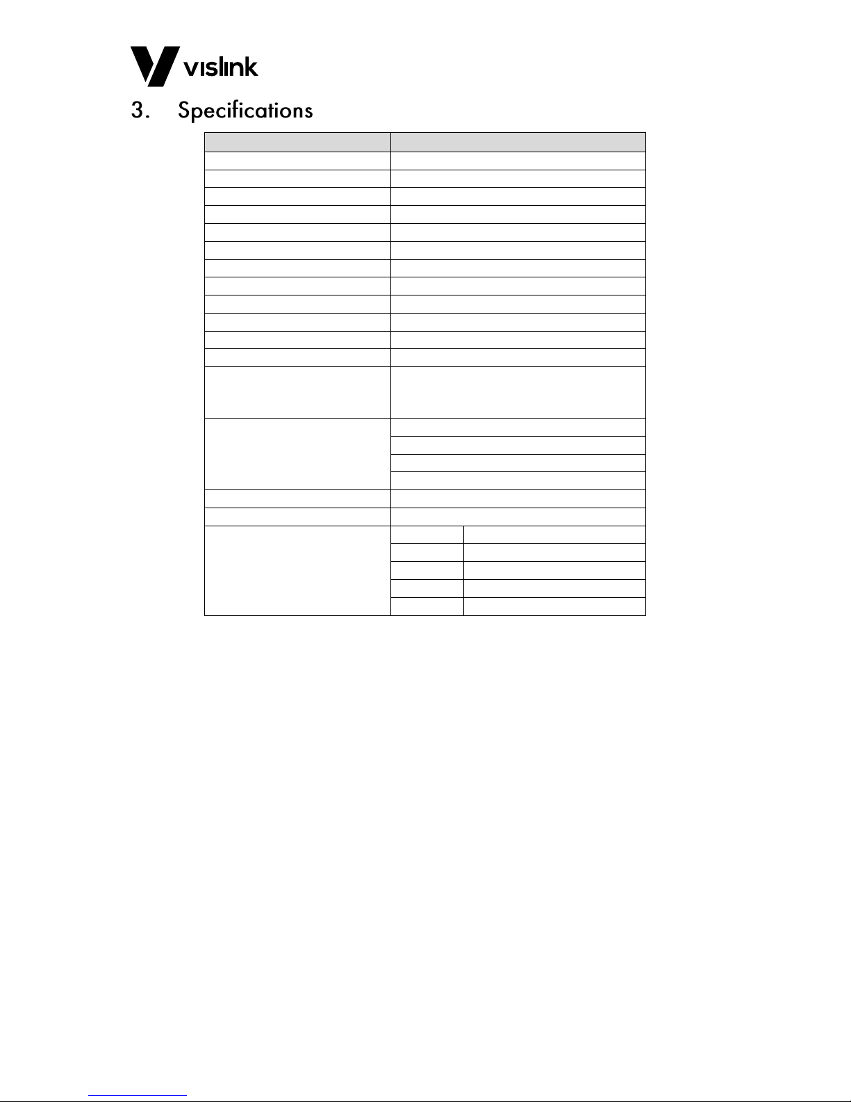
Feature
Details
Frequency Band
1.3 to 7.0 GHz
Output Power
Up to 20W
Linear Pre-distortion Correction
Automatically enabled
Reverse Power
Protected by circulator
Impedance
50Ω in/out
Spurious
Better than -60 dBc
Gain Flatness
+/-1 dB over frequency range
Gain vs. Temperature
+/-1 dB over temperature range
Third Order Intercept
+62 dBm
Input VSWR
1.4.1
RF Input Connector
N-Type
RF Output Connector
N-Type
Power Connector
2-pin DC power connector 12-28VDC (Or 20
to 30VDC with 20W Variant)
Neutrik Speakon NL2FX RS Part 340-0958
Monitoring LEDs
DC present
RF present
Load fault
Over temperature
Power Requirement
+10 to +30V DC at 150W (typical)
Weight
2.6 Kg
Environmental
Housing:
IP55
Safe use:
-20°C to 50°C (-4oF to 122oF)
To spec:
-10°C to 45°C (14oF to 113oF)
Altitude:
3500 m (11483 ft.)
Humidity:
95% long term
Table 3-1 Specifications

PLTX Digital Power Amplifier User Manual
Specifications
Issue No: 01 Page: 6
Ref: PLTX-ASUM-7xxx Copyright © 2017 IMT Ltd, trading as Vislink
This page is intentionally unused.

PLTX Digital Power Amplifier User Manual
Monitoring and Control Functions
Issue No: 01 Page: 7
Ref: PLTX-ASUM-7xxx Copyright © 2017 IMT Ltd, trading as Vislink
The PLTX unit has a dial to control RF output, LED display showing the unit supply voltage,
four status LEDs and a resettable push button 20A fuse.
Figure 4-1 Front Panel Layout
Number ID
Item
Description
Notes
1
RF output control
Rotary dial to control RF output
-
2
Power LED
DC input power present
Check load is 50Ω
VSWR LED
Indicates fault on RF output
Issue present if LED
is illuminated
RF Out LED
Output RF present
Output present if
LED is illuminated
Over temp LED
LED illuminates if PA
temperature exceeds 60°C
Check fan operation
3
Voltage display
Voltage of unit power supply
-
4
20A Circuit breaker
DC input over-current trip
Push to reset
Table 4-1 Control Panel Description

PLTX Digital Power Amplifier User Manual
Monitoring and Control Functions
Issue No: 01 Page: 8
Ref: PLTX-ASUM-7xxx Copyright © 2017 IMT Ltd, trading as Vislink
Figure 4-2 Front Panel Layout
Number ID
Item
Description
1
RF output
50Ω N-type connector
2
DC input
2-pin DC power connector 12-28V
3
HDMI Connector
Female v1.4 connector
4
SDI in
75Ω BNC
5
ASI in
6
Audio input 1-L
3-pin XLR
7
Audio input 2-R
Table 4-2 Front Panel Description
PLTX Digital Power Amplifier User Manual
Connector and Pin Outs
Issue No: 01 Page: 9
Ref: PLTX-ASUM-7xxx Copyright © 2017 IMT Ltd, trading as Vislink
Connector Type:
N-type 50Ω
Connector Type:
Neutrik NL2FC 2-pole Connector: CL120755
NOTE: Please request DC input connector information under part number: CL120755
Connector Type:
BNC connector 75Ω
Connector Type:
HDMI Female v1.4
Connector Type:
2x 3-pin XLR to 5-pin Lemo: CL120743-3
NOTE: Please request audio connection information under part number: CL120743.
Connector Type:
7-pin Lemo to 75Ω BNC connector
NOTE: Please request the optional L1700 LEMO to ASI/SDI cable under part number:
PLTX-ASSY-2001.
The fan derives power internally, and is always on when the unit has power connected.

PLTX Digital Power Amplifier User Manual
Connector and Pin Outs
Issue No: 01 Page: 10
Ref: PLTX-ASUM-7xxx Copyright © 2017 IMT Ltd, trading as Vislink
This page is intentionally unused.

PLTX Digital Power Amplifier User Manual
Installation Requirements
Issue No: 01 Page: 11
Ref: PLTX-ASUM-7xxx Copyright © 2017 IMT Ltd, trading as Vislink
Should you need to make any user-changes to the unit, ensure you read and understand
the following warnings and cautions.
CAUTION: Vislink strongly recommend returning any equipment requiring RF servicing to
the factory.
CAUTION: During the insertion or removal of interface connectors ensure that the
connectors are free from debris and be sure not to damage the contact pins.
WARNING: Switch off power supplies before removing covers or disconnecting any RF
cables, and before inspecting damaged cables or antennas.
WARNING: Avoid standing in front of antennas fed by high power amplifiers and never look
into the open end of a waveguide or cable where RF power may be present.
WARNING: Wipe off any water or fluids immediately.
WARNING: Do not open or modify the assembly.
1. Refer to Section 6.1 above regarding handling precautions.
2. Secure the unit using the mounting holes in the interface plate at the base of the
unit.
NOTE: Orientation of the unit is non-specific for operation.
CAUTION: The unit is fitted with a cooling fan integrated into the heat sink. Adequate free
air circulation is required around the unit to allow the fan to dissipate heat
generated by the amplifier.
CAUTION: Do not block the air inlet or exhaust ports. Ensure there is sufficient clearance to
allow free air circulation.
NOTE: See Section 3 (Specifications) for power consumption information.
CAUTION: The unit is designed to be splash proof (Rated to IP55). To prevent water ingress,
do not allow the unit to sit in a pool of water deeper than 90mm.

PLTX Digital Power Amplifier User Manual
Installation Requirements
Issue No: 01 Page: 12
Ref: PLTX-ASUM-7xxx Copyright © 2017 IMT Ltd, trading as Vislink
This page is intentionally unused.
Table of contents
Other Vislink Amplifier manuals


