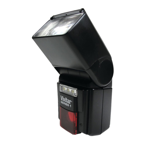
Vivitar 636AF Ni User manual


6 14 Description of Parts
1. Flash Window
7
15
2 Auto Focus Illuminator
3. Lockrng Wheel
4. Hot Shoe Contacts
5 Battery Compartment
6 Bounce Angle Indicator
8 7 Adjustable Bounce Head
16 8
AdJUStable
Swivel Base
9 Maxrmum Coverage Distance Scales
2 9
10
. Under Exposure Indicator
11.
On/O
ff
Switch
5 10
12
. Power On LED
13
Test Button
11
14
. Zoom Head Settrng lndrcator
15
Zoom Head
12
16
. Aperture/Drstance Scale
21
17
. Film Speed/ Aperture Selector
13
18
Frlm
Speed Wrndow
3
19
Mode Selector
20 Tone Swrtch
21
Flash Ready Indrcator
4 22 20mm
Wrde
Angle Panel
22

GETTING
STARTED
This manual
is
divided into two sections: the S
hor
t Co
ur
se and the Detailed
Sections
. The Short Course
gets you shooting flash pictures quickly with a minimum of instruction. The Detailed Sect
1on
provides .
detailed instructions about the extensive and versatile features of the flash. We urge you
to
read the
ent1re
manual
to
obtain the maximum enjoyment of your flash.
SHORT COURSE
The Short Course Section has been written to get you started shooting flash pictures quickly and easily.
is
based
on
using your camera
in
any
of
its Program settings with a 50mm nor
mal
AF
lens.
1 Make sure your camera
is
loaded with film.
2.
Slide open the flash Battery Compartment cover
(5)
and insert 4 fresh
AA
alkaline batteries following
the alignment diagram inside the compartment. . .
3.
Slide Battery Compartment cover back into place and make sure the Flash
On
/Off
Sw1tch
1s
in
the
OFF
posit1on
. . .
4.
Gently slide the flash fully into the accessory shoe
of
the camera and lighten the
Lock1ng
Wheel (3).
5. Turn the flash
ON
(
11
).
The Power
On
LED
(12) will glow.
6.
In
a few seconds. the Ready Indicator
(2
1) will glow.
7. Set the Mode Selector
(1
9)
to
TTL.
8. Push
or
pull Zoom Head (15)
to
the 50mm setting. . .
9. Rotate the Flash Head so that
it
is
pointing
in
the same
d1rectron
, and parallel
to
the lens.
1o. Make sure the camera
is
set to any
of
its program settings,
i.e.
P-Dual. P.
or
P-Hlgh.
11
Set 50mm
AF
normal lens
to
f/
22
.
12
. If the Ready Light
is
glowing, you'
re
ready
to
shoot.
2
SOME NOTES ABOUT YOUR NEW FLASH
This dedicated Vivitar Electronic Flash Unit
is
designed specifically for Nikon 2020 or
F501
Auto Focus
35mm
SLR
cameras. It provides automatic through-the-lens (
TIL
) flash exposures
in
addition
to
manual
flash.
F~rthermore
.
when the light
is
too dim for the camera
to
auto focus. the flash's built-in Illuminator
automatically provides a source
of
light for the camera to auto focus. This allows you
to
take sharply
focused pictures
in
very low light
or
even total darkness.
IMPORTANT: The auto focus mode selector
on
the front of the camera must
be
in
the
·s
·setting
in
order
for the Auto Focus Illuminator to function.
There are
two
modes
of
automatic TTL flash operation: Program and Aperture Priority.
In
the Manual
Mode, there are two manual flash power levels of FULL and -4
(1
/16th of FULL power). The
-4
setting
is
ideal for fast recycle lime when auto exposure
is
not needed.
A SIMPLE TTL FLASH TEST
To verify the TTL exposure operation,
an
actual exposure must
be
made with the flash attached
to
the
camera and film loaded
in
the camera. For test purposes, a light toned piece
of
paper can be positioned
at
the film plane
as
a film substitute and the camera back must
be
closed. Please note that light toned paper
may give incorrect responses due
to
differences
in
its reflective qualities versus actual film.
In
any case.
an actual flash exposure must be made
by
depressing the camera shutter release button. When the flash
is
fired and there
is
insufficient light output, the lightning symbol in the viewfinder and the Under Exposure
LED (1
0)
on
the flash will
bl
ink. In addition, when the flash Tone Switch (20)
is
ON
, there will be a beeping
sound. If there
is
enough light, no warnings will occur. (Nikon camera systems only warn
of
flash under
exposure
.)
3
DETAILED SECTION
1. Battery Loading
1)
Slide the Power Switch (11)
to
the OFF position.
2) Slide open the Battery Compartment Cover (5) and insert four fresh AA alkaline batteries.
3) When inserting batteries. be sure t
he
positive and negative terminals of the batteries are correctly
aligned
as
indicated on the diagram
in
the battery compartment. Remove
the
batteries if the unit
is
likely to be out of use for more than one month. Always change the batteries
in
complete sets of
four. NiCad batteries may
be
used with this flash.
2.
Attaching and Removing Flash Unit
1)
Before attaching or removing the flash unit. be sure to turn off the Power Switch (
11
).
2) To attach, slide the foot of the flash
1nto
the accessory shoe of the camera and tighten the Locking
Wheel (3).
3. Zoom Head
4
The Zoom Head (15) allows you to adjust the light coverage
of
your flash to coincide with the coverage
of
your camera
lens.
Simply push or pull the flash head to the setting desired.
Zoom Head Setting
28mm with 20mm Wide Panel
28mm
35mm
50mm
85mm
Camera Lens Coverages
20mm lens and
up
28mm lens and
up
35mm lens and up
50mm lens and up
85mm lens and up
NOTE: The guide number changes with each Zoom Head position as shown
in
'Table A' below.
TABLE
A:
Guide
Number
with
ISO
100 Film
Zoom
Head
Setting
28mm
Wi
th
20mm Wide Angle Panel
(Converts to 20mm coverage)
28mm 28mm lens and longer
35mm 35mm lens and longer
50mm 50mm lens and longer
85mm 85mm lens and longer
Guide
Number
(m/ft)
FULL -4
15
/50
3.75 /12
25/83 6.25/ 21
30/100 7
5/25
36/119 9/ 30
42
/139
10
.5/
35
5

4. Mode Selector
For
automatic flash exposure, slide the Mode Selector (19)
to
TTL.
For
manual flash, two power levels
can
be
selected: FULL and
-4
(1/ 16
of
full power)
5.
TTL Auto Exposure Range
6
The TTL auto exposure range changes with film speed, lens aperture. camera mode, and zoom head
setting. The following 'Table B'
for
I
SO
100 film indicates TTL auto exposure ranges for
any
of
the
program settings and most lens apertures you are likely
to
use.
For
slower films, divide these numbers
by
1
.414
for each halving
of
film speed. For faster film, multiply
by
1
.414
for
each doubling of film
speed. For example,
in
the
table below
at
50mm Zoom Head setting using f/4, the maximum distance
in
feet
is
30.
For
ISO
200 film, the maximum range
will
be
42
feet.
For
ISO
50
film,
the
maximum distance
will be
21
feet. Because
of
the
electronic design
of
the camera, using a film speed other than
ISO
1
00
w
ill
not
change
the
flash exposure range
of
the
Program
Mode
.
Program
Mode
or Lens
Aperture
Pr
ogr
am
mode
1.4
2.8
5.6
8
11
16
22
TABLE B:
TTL
Auto Coverage Range
(ISO
100)
ZOOM
HEAD
SETTING
28mm +
Wide Adapter 28mm 35mm
0.7
-2.7 m 0.7-4.5 m 0.7-5.3 m
2.3-9
ft
2.3-15 fl 2.
3-
17
.5
ft
1.4
-
10
.7
m 1.4-17.8 m 1.4-21.4 m
4.5-35
ft
4.5-59 fl 4.
5-71
ft
1-7.5 m
t-12
.5
m 1-
15m
3.3-25
ft
3.3-41 fl 3.3-50
ft
0.7
-
5.4
m 0.7-8.9 m 0.7-10
.7
m
2.3-
18
ft
2.3-29 fl 2.3-35
11
0
.7
-3.75 m 0
.7
-6.25 m 0.7-7.5 m
2.3-12
ft
2.3-20 fl 2.3-25 fl
0.7-2.7 m 0.7-4.5 m 0.7-5.3 m
2.3-9
ft
2
.3
-15
ft
2.3-17.5 fl
0.7-1.9 m 0.7-3.1 m 0.7-3.75 m
2.3-6.3
ft
2.3-10 fl 2.3-12
ft
0.7-1.4 m 0.7-2.3 m 0.7-2.7 m
2.3-4.6
ft
2.3-7.6
fl
2.3-9
ft
0.7-09
m 0.7 1.6 m 0.7-1.9 m
2.3-3
ft
2.3-5.
311
2.3-6.3"
07-1
.1 m 0.7-1.4 m
2.3-3.6
ft
2.3-
4.6"
50mm 85mm
0.7-6.4 m
0.7
-7.5 m
2.3-21 fl 2.3-25 h
1.4-25.7 m 1.4-
30
m
4.5-85
11
4.5-100
ft
t-
18
m 1-2
1m
3.3-60 fl 3.3-
69
ft
0.7-12.8 m 0.7-15 m
2.3-42
11
2.3-
50
ft
0.7-9 m 0.7-10.5 m
2.3-30 fl 2.3-35 h
0.7-6.4 m 0.7-7.5 m
2.3-21
11
2.3-25 h
0.7-4.5 m 0.7-5.3 m
2.3-15
11
2.3-17
.5
ft
0.7-3.3 m 0.7-3.8 m
2.3-1 1
11
2.3-12.5
ft
0.7-2.25 m 0.7-2.6 m
2.3-7.
5"
2.
3-9
fl
0.7-1
.6 m 0.7-1.9 m
2.3-5
.3
" 2.3-6.3 fl
7

6.
Aperture/Distance Scale
The Aperture/Distance Scale (t
6)
on
the rear
of
the unit shows the combinations
of
maximum
operating distances (9) and lens apertures for the film speed shown
in
the window (t
8)
. It's based on
the zoom head being set
at
the 35mm position. This combination will help you select the lens aperture
with Aperture Priority and Manual mode operation. Example:
In
Aperture Priority with
ISO
100 film.
aperture set
at
f/2.8. the maximum d
is
tance will
be
35
f1
(indicated just above the lens aperture 2.8
on
the Aperture/D1stance Scale (16). With changes
in
the Zoom Head position. the maximum operating
d1stance will vary from that shown
on
the scale as follows:
Zoom Head Setting
28mm with 20mm Wide
Angle Panel
28mm
35mm
50mm
85mm
Maximum Operating Distance
40% shorter than indicated
20% shorter than indicated
as shown
on
the scale
20% longer than
in
dicated
40% longer than indicated
7. AF Illuminator lor Auto Focusing
8
In
low light. or lotal darkness. with the flash in the
ON
position. the
AF
Illuminator
(2)
will automatically
be
activated when the camera's shutter release
is
depressed half-way. Light from the Illuminator will
be
projected
on
the subject
to
activate the camera's auto focus mechanism. The effective range
of
the
Illuminator
IS
about 1-
10
meters
(3.
3-33 feet) with a 50mm normal lens. If you use a zoom lens with a
small aperture. the maximum effective distance will
be
shorter than above and you may want
to
use
manual focusing. IMPORTANT: The flash Auto Focus Illuminator will only funct
ion
when the auto focus
mode selector located
on
the front
of
the camera
is
set
to
·
s·
8. Under Exposure Warning Signal
When the flash
is
fired and there is insufficient
l1ght
output. the
lightn1ng
symbol
in
the viewfinder and
the Under Exposure
LED
(1
0)
on
the back of the flash will blink.
In
addition. when the flash Tone Switch
(20)
IS
ON
. there will
be
a beeping sound. If there
is
enough light. no warn
in
gs will occur (Nikon
camera systems only warn
of
flash under exposure.)
9. OPERATION
A. Program
Mode
Operation
:
1
Set
camera
to
one
of
the three Program Modes· P-DUAL. P, or P-HI.
2
Set
camera lens to minimum f/ stop (Note:
AF
.
AI
/S
or
E·type lenses must
be
used. See camera
instruction book for further information about lenses.)
3.
Set
Flash Head
to
desired lighting angle and the zoom position
to
coincide with the focal length
of
the lens used.
4
Set
the flash Mode Selector (19) to the TTL position.
5
Sl
ide the flash
On
/Off
Sw1tch
(1
1)
to
the
ON
position: the Power
LED
(
12
) will light. indicating that
the flash unit
is
on
.
6. After the flash Ready Light
(2
1) glows. look
in
the viewfinder and press the shutter release half-way.
You will see a
red
lightning symbol and a red '125'
on
the right hand. vertical column
of
the VIewfinder
This indicates the flash
is
ready and the correct shutter speed for flash has been set. For other
viewfmder indications. see your camera's instruction manual. The camera and flash are now ready for
automatic TTL flash photography.
7. Make sure that the subject
IS
w1thin
the exposure range (see Table B) and press the shutter release
button
all
the
way
to
take the picture.
9

8.
If
there
is
not
enough light. the
lig
htning symbol
in
the camera viewfinder and the Under Exposu
re
LED
(t
0)
on
the
flash will flicker.
In
addition.
if
the Tone
Sw1tch
is
in
the
ON
position. there will be a
beeping sound.
If
any
of
these under exposure indications occur. move closer
to
the subject or switch
to
A-Mode operation and use the widest aperture (smallest !/number).
B. A-Mode Operation
1.
Sel
camera
Ia
the
A-Mode and select the desired lens ape
rt
ure. Check 'Table B'
to
ensure that the
aperture selected permits
TI
L exposures f
or
distances greater than
the
flash-to-subject distance. The
wider the aperture selected (smaller number).
th
e gr
ea
ter the
fl
as
h
ra
nge and better overall fl
ash
performance.
2.
Set
flash Mode Selector (1
9)
to
the TTL position and follow steps 3 through 8 above
in
Program
operat
ion
.
C. Fully Manual
Op
eration
1.
Set
camera shutter speed
to
1I 125
or
slower.
2.
Set
Mode Selector (1
9)
of
flash unil
to
FULL or
-4
. The
-4
setting
is
suitable for fast recycle time
and
for
auto
win
d
er.
rapid sequence shooting.
3.
In
Ihis mode. the TTL auto exposure signal from
the
camera
wi
ll
no
t
be
transmitted
to
the flash unit:
therefore. the aperture must be
set
ma
nually. The proper aperture can be fo
un
d
by
dividing the guide
number
by
the flash-to-subject distance. Example:
In
the FULL power position. if you are using
ISO
1
00
film
wi
th the Zoom Head
in
the
35mm position,
the
gu
id
e number
is
1
00
for
fee
t or 30 for meters.
If
the flash-to-subject distance
is
3.7
m (12
ft)
. the proper lens aper
tu
re will
be
f
/8
(1
00/
1
2=8
3
or
30/ 3.
7=8
.1).
If
you
are using the -4 mode.
the
guide number will be 25 for feet or 7.5
for
meters.
4. Slide the On /Off Switch (t
1)
to
the
ON
position. After the Ready Light
(2
1) glows. the flash
is
ready
to
shoal.
Note
: The under exposure indicators do not function
in
manual mode.
10
Bounce Flash Photography
By
aiming the Flash Head
at
ceilings and walls. bounce flash photography can offer softer. more
professional quality lighting. The head
of
the flash can be angled
up
to
90
degrees vertically and/or
swiveled
up
to 180 deg
to
the left
and
90
deg
to
the right. Automatic exposure bounce flash photography
in
Program
or
Apertu
re
Pnority modes can
be
easily done
by
fol
lowing the Program
or
Aperture Priority
instruclions above.
NOTE: When
us
i
ng
color film.
it
is
better
to
bounce
the
light off white or neutr
al
colored
su
rfaces only.
2. Take care in selecting
the
bounce angle
so
that
direct light from the flash
head will not enter the picture area. ·
Accu-Trak™Circuit
This flash incorporates a special circuit that
pe
rmits correct exposures even
at
short flash-to-subject
distances.
It
functions automatically and requires
no
special settings.
Test Button
The flash Test Button
is
only used
to
make sure the flash functions. When
the
flash
is
on and
the
Ready
Light glows. the Test Button can be depressed
to
fire the flash.
Pl
ease
no
te the Test
Button
op
erat
es
ind
epe
ndently
of
the TTL auto ex
posure
mechanism
and
cannot
be used
for
correct
exposure tests.
CAUTIONS
1.
If
the
un
it
fa
ils to operate, please refer it to qualifi
ed
service personne
l.
2. Remove the batteries
if
the unit
is
not
in
use
for any period exceeding one month.
3. Keep the unit dry and store
in
a moisture-free environment.
11

Specifications
Guide
Number
(ISO
100/ Feet):
Zoom
Flash Head
Setting
TTL & Full Power Mode
-4 (1/ 16) Power Mode
Guide
Number
(ISO
100/Meters):
Zoo
m Flash Head
Setting
TTL & Full Power Mode
-4 (1
/16)
Power Mode
Auto
TTL
E
xposu
re
Coverage
Auto
Focus
Illum
in
ato
r Ra
nge
Power
Source
4
AA
alkaline batleries
NiCad balteries
Fl
ash
Durat
ion
in Full
Pow
er
Mode
Color
Temperature
A
ccu-
Tr
ak
™
Circuitry
12
85mm
50mm
35mm
28mm
139 119 100 83
35 30
25
21
85mm
50mm
35
mm
28m
m
42
36
30 25
10.5 9 7.5 6.3
See Table B
3-33 Feet (t -1
0 Meters) with 50mm fI 1.8 lens
Re
cycle
T
ime
0.
3-8
seconds
0.2-6 seconds
1/ 1000-t /50.000
5700° Kelvin (Daylight)
Numb
er
of
Flashes
120-2500
80-1500
Yes. provides correct automatic exposures
when shooting close-up photographs.
20mm•
50
12
20mm·
15
3.75
Auto
Thyr
i
sto
r™
Auto-Off
Circuitry
Zoom
Flash
Head
Vertical
Bounce
Flash
Hor
izo
ntal
Bounce
Fl
ash
Underexposure
Indication
Flash
Test
Button
Flash
Ready
Indicator
Di
mensions
Weight
Accessor
ies Incl
uded
Optional
A
ccess
or
ies
Yes. permits more flashes and faster
recycle time per set of batteries.
Yes. with "
One-Touch
" power on by depressing
camera's shutter bulton half way down.
28rnm. 35mm.
50mm
& 85mm
0°-15°-30°-45°
-60°-75°-90
°
270° Rotation
Yes. three ways: VIewfinder LED.
Flash LED and Flash beep tone.
Yes
Yes
5.2
" X 3.0" X 3.5"
(t32
mm
x
79
mm x 88 mm)
12
ounces (340 grams)
w1thout
batteries
20mm Wide Angle Flash Panel"
Flash
F1lter
Set. 1ncludes adapter and
four filters
Specif1cat1ons subtect to change w1thout notice
13
Table of contents
Other Vivitar Camera Flash manuals

Vivitar
Vivitar VIV-DF-186 User manual

Vivitar
Vivitar 283 User manual

Vivitar
Vivitar VIV-SF-6000 User manual

Vivitar
Vivitar POWER ZOOM DF-383 User manual

Vivitar
Vivitar 283 User manual

Vivitar
Vivitar VIV-DF-7000 User manual

Vivitar
Vivitar 283 User manual

Vivitar
Vivitar 285 HV User manual

Vivitar
Vivitar VIV-PRO-648 User manual

Vivitar
Vivitar 283 User manual

Vivitar
Vivitar DF200 User manual

Vivitar
Vivitar Vivicam 2800 User manual

Vivitar
Vivitar 285 HV User manual

Vivitar
Vivitar 285 HV User manual

Vivitar
Vivitar 365 User manual

Vivitar
Vivitar VIV-DF-3000 User manual

Vivitar
Vivitar 283 User manual

Vivitar
Vivitar 283 User manual

Vivitar
Vivitar 283 User manual

Vivitar
Vivitar 202 User manual