組立て方
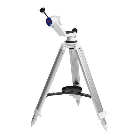
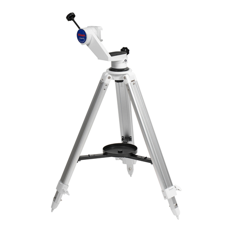
① 三脚を設置します。
高さ調整ネジをゆるめて、好みの高さと
なるように調整します。三脚は開き切った
状態とします。また3本の脚の長さを見な
がら、上面が水平になるように調整してく
ださい。調整後はゆるまないように高さ調
整ネジをしっかりとしめてください。
② 方位調整ツマミ2本を十分ゆるめておき
ます。
③ 写真を参考に三脚の水平支点と方位調
整ツマミの位置をあわせて三脚に搭載
します。搭載後は架台固定ボルトをしめ
て固定してください。目安として指3本
でしめられるくらいの力でしめます。そ
の後方位調整ツマミをしめます(強くし
めないでください)。
高さ調整ネジ
SXG-S71三脚→
方位調整ツマミ
方位調整ツマミ
方位調整ツマミ
水平支点
GP2極軸ベース
架台固定ボルト
① ② ③
④ ガイドパックプレートをGP2極軸ベース
に取付けます。
付属 のネ ジM 6 × 1 6 を4 本 およ び六角 レ
ンチ5mmを使用します。ゆるまないよう
にしっかり固定してください。
⑤ ガイドパックプレートにガイドパック用
ウェイト軸を取付けます※。ゆるまないよ
うにしっかり固定してください。
※ 六角穴付ボルト(セット済)1本を取外し
てから作業します。
⑥ バランスウェイトWT1kgを取付けます。
ウェイト脱落防止ネジを取外し、ウェイト
を通します。その後ウェイト固定クランプ
をしめ、ウェイト脱落防止ネジを元通り
に取付けます。
六角レンチ
5mm
ガイドパック用
ウェイト軸 ウェイト固定
クランプ
ウェイト脱落
防止ネジ
バランスウェイト
WT1kg
ガイドパック
プレート
ガイドパック
プレート
④ ⑤ ⑥
⑦ 市販のカメラ雲台など撮影機器を取付け
ます。
⑧ ガイドパックプレートに明視野照明を取
付けます。
⑨ D D - 3 二 軸コ ン トロ ー ラー の R A(赤 経)
モーター用コードを取付けて完成です。
※ DD-3のご使用方法につきましてはDD-3
に付属の説明書をお読みください。
明視野照明
RA(赤経)
モーター用コード
六角レンチ
5mm
ガイドパック
プレート
カメラ雲台
(市販品)
⑦⑧⑨
Assembling the GP2 Photo Guider S
①Setting up the Tripod
Loosen the extension clamp knob on
the tripod leg so that the tripod leg can
be adjusted at the desired length. Pull
the tripod legs apart until each leg is
fully extended. Stand the tripod to be
level on the ground at the desired
height by readjusting the length of
each tripod leg. Tighten the extension
clamp knobs securely.
②Loosen the two azimuth adjustment
screws fully.
③Place the bottom of the equatorial body
over the tripod headso that the azimuth
adjustment screws are above the peg
on the tripod head as shown in the
figure. Attach the equatorial body to
the tripod head and tighten the fixing
bolt by hand. Then tighten the azimuth
adjustment screws.
(Do not tightenstrongly.)
clamp knob
SXG-S71 Tripod→
Azimuth
adjustment screw
Azimuth
adjustment
screw
Azimuth
adjustment screw
Peg
Fixing bolt
GP2 Equatorial
body
① ② ③
④Attach the Camera/counterweight
mounting block on the head of the
equatorial body with the supplied 4 of
M6-16mm long bolts. Tighten the bolts
securely by using the supplied Allen
wench.
⑤Thread the counterweight shaft into
one end of the Camera/counterweight
mounting block until tight.
(Remove the attached 1/4 inch bolt in
advance to thread.)
⑥To install the counterweight 1 kg on the
counterweight shaft,remove the safety
screw on the end of the counterweight
shaft and slide the counterweight on to
the center of the shaft.
Tighten the lock scre w o n t h e
counterweight and replace the safety
screw in place.
Allen wench
Counterweight shaft Lo ck screw
Safety screw
Counterweight 1kg
Camera/counterweight
mounting block
④ ⑤ ⑥
⑦Install a commercially available Ball
head on the other side of the
Camera/counterweight mounting block
as shown inthe figure.
⑧Install the illuminator on the center of
the Camera/counterweight mounting
block.
⑨Connect the R.A motor cable of the
DD-3 hand controller to the built-in
R.A. motor on the equatorial body and
finish the setting up.
※For usage of the DD-3 dual-axis
controller, refer to instruction manuals
for the DD-3 hand controller.
Illuminator
R.A motor cable
Allen wench
Camera/
counterweight
mounting block
Ball head
(Sold commercially)
⑦⑧⑨
36
