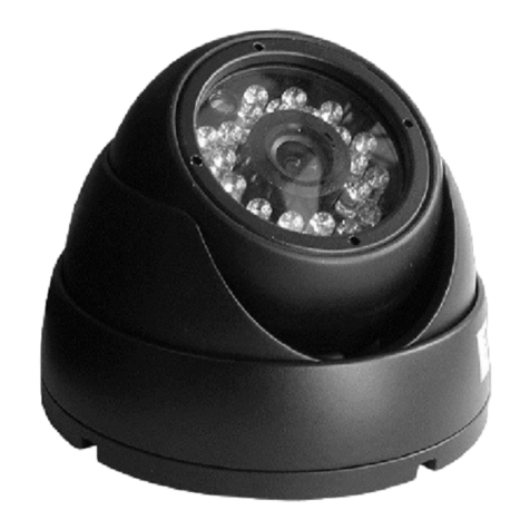
ViziT ODC-701-3.6 User manual

Troubleshooting
In case your camera does not operate properly, make sure that it is installed and wired properly, and check the
below suggestion:
b. Make sure that you use a recommended AC-DC power supply unit with output voltage 12 VDC.
c. Check that all cables are connected correctly, and there is no misconnection in the wiring.
a. Check that your monitor is correctly adjusted.
b. Make sure that the glass in front of the lens is clean, otherwise the image quality may be affected.
To clean the glass use a piece of soft dry cloth. Do not use liquid cleaners, aerosol cleaners or
1. When there is no image on the monitor’s screen:
2. he is not clear (blurred):
a. Check if your power supply unit(s) is plugged into the mains outlet.
abrasive agents.
3
a. Check your monitor’s contrast / brightness settings.
b. Make sure that the camera ball is positioned correctly, and not pointed toward a corner or direct source of light.
a. Check the lamps near your camera location. Note that filament incandescent lamps may affect the image
colours. For illumination of the area in front of the camera, use fluorescent or white LED lamps.
a. The camera may be close to a high voltage source, such as a power generator. If this is the case, change
location of your camera.
b. The video cables are not connected properly, check for any misconnection.
c. The length of the cable between the camera and monitor is more than 20m. Use a coax or composite cable for
video surveillance systems.
When t image
. When the image is too dark or too bright:
4. When the colour is not displayed correctly with the lamplight illumination:
5. When the image has interference:
If the camera still does not operate properly, please contact the service representative. Do not attempt to service
the camera by yourself, refer all services to qualified personnel.
4
ODC-701-3.6 VIZIT
SAFETY INSTRUCTIONS
PARTS LIST
INSTALLATION
–
or atmospheric precipitation
.
1
1
1 .
*
is a dome CCD colour camera for outdoor surveillance intended for use in video doorphones
and access control systems.
In order to protect the camera, avoid placing it under direct sunlight .
Please ensure that the supply voltage is within the valid specifications
Do not attempt to service the camera by yourself. Please refer all services to qualified service personnel.
Camera pc.
Operating instruction pc.
Fastening kit pc
Choose the camera location with regard to the required field of view.
See Fig. 3 for the best camera location and its field of view.
·
·
·
range indicated in
Hermetic Camera ODC-701-3.6
OPERATING INSTRUCTION
Figure 1 - Hermetic camera ODC-701-3.6
·
·
·
Weather-resistant & Vandal-proof
auto ON for illumination in the darkness
Wide range of operating temperatures
Metal housing
IP Rating: IP66
24 InfraRed LEDs
Colour image auto switch to B/W in dark environment
·
1. (1)
(5)
.
2.
(6)
(7) .
3. (2) (3)
.
4.
5.
Remove the mounting base by loosening the locking screw
with the hex-nut wrench supplied, and unscrewing the
locking cover counter-clockwise
Choose location* for the camera on a wall or the ceiling,
and fix the mounting base securely with screws
Connect the camera to your monitor and power supply unit.
Check if the monitor shows picture from the camera.
To adjust the picture, set the ball to the suitable
position by rotating the ball and middle cover.
Fix the camera’s position securely by tightening the
cover (4) and fastening the locking screw .
(4)
(4)
(5)
and anchors supplied
Put the ball , middle cover and
on the mounting base Tighten the locking cover leaving
enough space for the camera ball to rotate.
camera locking cover
camera
locking
(4)
Figure Camera installation2 -
1
2
3
4
7
1
red
black
yellow
black
Manufacturer: ,
Tech. support: www.vizit-group.com
MET Co. Ltd. China

Where the length of the cable connecting your monitor and the camera exceeds 20 m, use a coax or composite
cable specially designed for video surveillance systems. This will considerably reduce possible image distortion.
2. Connecting the ODC-701-3.6 camera to VIZIT multi-apartment video doorphones.
Control Unit
BUD-302M
CONNECTIONS
1. Connecting the ODC-701-3.6 camera to VIZIT individual video doorphones.
BKM-
Caution Ev
VIZIT
Connect the camera wires to the corresponding terminals of your VIZIT monitor or commutator .
Do not connect the camera wires to the terminal of the doorstation.
See an example of connecting two cameras to the individual doorphone on Fig. 5.
***
!
- = 2.5
-
1.5 ( )
3 -
Camera altitude above the floor m
Distance from the center of the entrance door
= m horizontal
Figure Camera field of view
yellow VO (video out) -
black VGND video ground - ( )
black GND ground - ( )
red Ec (supply voltage for camera- )
Figure Wires, their colour and destination4 -
32
Figure Two cameras with monitor VIZIT-M4 0C in individual video doorphone ODC-701-3.6 4
5 -
-18
+18
+12
-12
4
3
1
2
2
1
1
2
12
1
3
4
12
2
1
2
2
1
V
1A
50
COLOUR
LINE
GND
+E
Ev
Ec
LC
Doorstation
BVD 403A-
Power supply
BPD18/12-1-1
V )
LECTRO MECHANICAL
LOCK
E
(12 1А,
Camera
ODC-701-3.6
L N-
GND
L N+
VI1
+E
DATA
Ec1
Ec2
GND
VI2
- 440
Monitor
VIZIT M C
yellow
black
red
yellow
black
red
Camera
ODC-701-3.6
3
1
2
3
1
2
3
1
2
2 1 3
Connect two black wires in the camera
to each other.
Camera
ODC-701-3.6
yellow
black
red
to commutators and /
or
distribution amplifiers
Figure Camera in multi-apartment video doorphone 6 - ODC-701-3.6
SPECIFICATIONS
black
black black
19w/14.4v/EU
(12V/1.5A)
Power supply unit
In-line
DC jack
Model ODC-701-3.6
Colour system
Image sensor
Effective pixels Horizontal H x vertical V ( )
Horizontal resolution
Lens
Angle of view diagonal vertical ( / / )horizontal
Illumination
Infrared LED ranges
Sensitivity
Scanning system
Video output
Power supply
Current consumption
Dimensions (diameter x height)
Weight
Ingress protection
Operating temperature
PAL
1/3" RJ 2341 Sharp CCD
976 (H) x 582 (V)
700 TVL
Board 3.6 mmf =
92 80 62 / /° ° °
24 Infrared LEDs
10 m
0 ( )Lux Infrared LEDs on
625 Lines Hz, 50
1 / 75 , compositeVp-p Ohm
12 VDC ± % 10
210 max. мА
94 х 68.5 mm
350 g
IP 66
- 30° C …+ 50° C
1
2
to
doorstation
VIDEO
Connect GND of
power supply unit
and control unit
RX
SP-
TX
+DL
-DL
OP
LINE
Ek
SEL
GND
TM
SP+
GND
MIC
+E
DSD
1
2
~ 220 V
Hz 50
+E
GND
Other ViziT Digital Camera manuals
