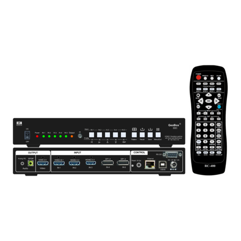
VNS GeoBox G901 User manual

G901 User Guide Document: G901-2
---------------------------------------------------------------------------------------------------------------------------------------------
0
G901 User Guide
5x1 Seamless UHD switcher with Quad Split Views
Input: up to 4096*2160 @60Hz, 7680*2160 @30Hz in HDMI2.0b,
7680*4320@30Hz in DP1.4, 4:4:4 chroma sampling
True 10-bit processing and up/down scaling
Programmable Output resolution: up to 4096*2267/60Hz or 7680x1234/60Hz
Selectable refresh rate: 24/30/50/60/100/120Hz, 8/10 bits
PIP/POP & 3/4 split Multiview
5 in / 1 out seamless switching
3D format conversion
(Important Note: If the output resolution can’t be supported by the monitor,
user will not see any image on the screen.)
Tel: +886-2-2792-2819 Cell: +886-935-678-033
Skype: vns-inc, Version: 1.52
Website: www.vnstw.com
The absolute opposite of ordinary

G901 User Guide Document: G901-2
---------------------------------------------------------------------------------------------------------------------------------------------
1
Table of Contents
Disclaimer/Copyright statement........................................................................................................ 3
Warranty/RMA and FCC/CE statement.............................................................................................. 3
Introduction……………………………………………………………………………............................ 4
Outlook………………………………………………………………………………………………………. 5
User Guide
1. How to use IR Remote Controller.............................................................................................. 6
1.1. Key pad functions and extension cable……………………………………………………… 6
1.2. Change OSD language…………………………………………………………………………… 7
1.3. Individual OSD control in multiple unit application………………………………………... 7
1.4. OSD Lock and Unlock…………………………………………………………………………… 7
1.5. Change OSD location……………………………………………………………………………. 7
2. System Reset……………………………………………………………………………………………. 8
3. Front panel…………….......……………………………………………………………………………. 9
4. Back panel………………………………………………………………………………………………. 9
5. Seamless input source switching……….……….….................................................................. 10
6. Output signal and output port configuaration....................................................…………....... 10
7. Typical system connection…………………………………………………………………………… 11
8. Select input port
8.1. Select input port from OSD……………………………………………………………………… 11
8.2. Select input port from remote controller……………………………………………………… 12
9. Set output resolution and signal type ……………………………………………………………… 12
9.1. Select output resolution from remote controller……………………………………………. 13
9.2. Select output resolution from OSD preset mode..…………………………………………. 13
9.3. Programmable output resolution………………………………………………………………. 14
9.4. Enable 10-bit deep color output ………………………………………………………………. 15
9.5. HDR (BT.2020) processing……………………………………………………………………… 16
10. How to check system Information…………………………………………………………………… 16
11. System Control and setup……………………………………………………………………………… 17
11.1. Box ID…………………….................................................................................................... 18
11.2. Multi-units controlled by one remote controller............................................................ 18
11.3. RS232 setting……………………………………………………………………………………. 18
11.4. Ethernet setting................................................................................................................. 19
12. PIP/POP multiple window display
12.1. Main menu……………………………………………………………………………………….. 20
12.1.1. [Display]—select different multi-window display types…………………………… 20
12.1.2. [Size]—Change sub-window image size under [PIP] & [3x SBS]………………… 22
12.1.3. [Position]—Set PIP image position……………………………………………………. 22
12.1.4. [Ratio]—Display full range image or keep original aspect ratio…………………. 22
12.1.5. [Source] selection………………………………………………………………………… 23
12.1.6. [Rotation]: Sub-window image rotation………………………………………………. 24
12.1.7. [Overlap]-- Adjust cropping area and aspect ratio…………………………………. 25

G901 User Guide Document: G901-2
---------------------------------------------------------------------------------------------------------------------------------------------
2
12.1.8. [Color]—Color adjustment……………………………………………………………… 26
12.2. PIP (picture in picture) ………………………………………………………………………… 26
12.3. POP (PBP)--Picture outside picture….……………………………………………………… 26
12.4. [SBS 2/1]—2/3:1/3 side by side……………………………………………………………….. 27
12.5. [3x SBS] in landscape…………………………………………………………………………. 28
12.6. [3x T/B]……………………………………………………………………………………………. 29
12.7. Other 3 split views……………………………………………………………………………… 30
12.8. 4 split views……………………………………………………………………………………… 31
13. Advanced system settings
13.1. EDID setting………………………………………………………………………………………. 32
13.2. Quick PIP ON/OFF and two input seamless swap……………………………................... 33
13.3. Image rotation and flip…………………………………………………………………………. 34
13.4. Image cropping in main and PIP/POP (sub-windows) …………………………………… 35
13.5. Flexible aspect ratio adjustment……………………………………………………………… 35
13.6. System Standby and automatically turn off output Signal............................................ 36
13.7. Change Background Color in blue or black……............................................................. 36
13.8. Native 1:1 image display……………………………………………………………………….. 37
13.9. Turn off splash screen Logo…………………………………………………………………... 37
13.10. Image freeze……………………………………………………………………………………… 37
13.11. Audio output setting……………………………………………………………………………. 38
13.12. HDCP control…………………………………………………………………………………….. 38
14. Video Wall settings....................................................................................................................... 39
14.1. [Zoom] –Split Source Image............................................................................................ 39
14.2. [Pan] –Assign Image Position.......................................................................................... 40
14.3. [Overlap] –Bezel Compensation and Position Alignment............................................. 40
14.4. [Position]………………………………………………………………………………………….. 41
15. 3D format conversion and active/passive 3D application………………………………………… 41
16. WebGui and GCT PC Tool (GeoBox Control Tool)………………………………………………… 45
16.1. WebGui……………………………………………………………………………………………. 45
16.2. GeoBox Control Tool (GCT) ……..…………………………………………………………… 46
17. Save System Settings………………………………....................................................................... 46
18. Load Profile Setting……………………………….......................................................................... 47
19. Application case study
19.1. Image cropping for LED display……………………………………………………………… 48
19.2. Front end processor……………………………………………………………………………. 49
19.2.1. G901 as front-end processor for video wall…………………………………………. 49
19.2.2. G901 as front-end processor for projection system……………………………….. 50
19.3. 4K scaler switcher……………………………………………………………………………… 51
Technical support
20. Trouble shooting
20.1. No image on the screen………………………………………………………………………… 52

G901 User Guide Document: G901-2
---------------------------------------------------------------------------------------------------------------------------------------------
3
20.2. Intermittent or loss of input signal……………………………………………………………. 52
20.3. Video Quality issue………………………………………………………………………………. 53
20.4. Abnormal display in Front panel LED indicators…………………………………………… 53
20.5. Synchronization issue in the outputs………………………………………………………… 54
20.6. Call for technical support………………………………………………………………………. 54
21. Safety precaution and maintenance…………………………………………………………………… 54
22. Warranty and RMA policy……………….………………………………………………………………. 55
Specifications................................................................................................................................... 56
Revision history............................................................................................................................... 57
Disclaimer/Copyright Statement
Copyright 2022, VNS Inc. All Right Reserved
This information contained in this document is protected by copyright. All rights are reserved by VNS Inc.
VNS Inc. reserves the right to modify this document without any obligation to notify any person or entity of such
revision. Copying, duplicating, selling, or otherwise distributing any part of this document without signing a non-
disclosure agreement with an authorized representative of VNS Inc. is prohibited. VNS Inc. makes no warranty for
the use of its products and bears no responsibility for any error of omission that may appear in this document.
Product names mentioned herein are used for identification purposes only and may be trademarks of their respective
companies. Limited Warranty and RMA statement
This device is designed and tested to the highest standards and backed by two years’ parts and labor warranty.
Warranties are effective upon the first delivery date to the end customer and are non-transferable. Warranty related
repairs include parts and labor, but do not include repair of faults resulting from user negligence, special
modifications, abuse (mechanical damage), shipping damage, and/or other unusual damages. The customer shall
pay shipping charges when the unit is returned for repair. Manufacturer will pay shipping charges for return
shipments to customers.
Manufacturer does not assume responsibility for consequential damages, expenses or loss of revenue,
inconvenience or interruption in operation experienced by the customer. Warranty service shall not automatically
extend the warranty period.
User can pay extension fee to extend the warranty period. Please contact us for more details. In the event that a
product needs to be returned for repair, inform manufacturer and ask for a Return Material Authorization number.
FCC/CE statement
This equipment has been tested and found to comply with the limits for a Class A digital device, pursuant to part 15
of the FCC Rules. These limits are designed to provide reasonable protection against harmful interference when the
equipment is operated in a residential / commercial environment. This equipment generates, uses, and can radiate
radio frequency energy and, if not installed and used in accordance with the instruction manual, may cause harmful
interference to radio communications. Operation of this equipment in a residential area is likely to cause harmful
interference in which case the user will be required to correct the interference at his own expense.

G901 User Guide Document: G901-2
---------------------------------------------------------------------------------------------------------------------------------------------
4
Introduction
G901 is multiple purpose video processor for seamless switcher, scaling up and down, image
flip/rotation/cropping, video wall, PIP/POP, 3D format conversion and multi-viewer functions. The input
supports various input sources and input timings. It is an ideal front end processor for big display system
required 4k/60 input and output.
5 input ports (3x HDMI, 2x DP) and 1x HDMI outputs are designed in G901. Input supports up to
4096*2160 @60Hz, 7680*2160 @30Hz in HDMI input and 7680*4320 @30Hz in DisplayPort input with 4:4:4
chroma sampling. No VESA standard input timings are also supported up to 600 MHz.
Programmable output supports up to 4096*2267 @60Hz or 7680*1234 @60Hz output resolution. The
range is from 800-7680 (with 8 pixel/step under 230Mhz, 16 pixel/step above 230MHz) in horizontal and 720-
3840 (with 1 pixel/step) in vertical. The maximum resolution is limited to 600MHz. Output refresh rate can be
selected from 24/30/50/60/100/120Hz.
It is integrated with 10-bit high end processor, motion adaptive de-interlace, low angle smooth
algorithm, 3:2/2:2 pull-down cadence. Programmable EDID enables optimized input timing to get the best
video quality.
It is integrated with color adjustment in Brightness, Contrast, Hue, Saturation, Sharpness, color
temperature and discrete RGB gain adjustment. Automatically detect and process HDR BT. 2020 input signal
and output with full color 4:4:4 RGB SDR signal. User can select deep color mode with true 10-bit color output
to get smooth gradient color.
Video wall function in G901 can crop specific location & resolution in source image for programmable
output. Overlap function allows user to change image position, aspect ratio and cropping area up to +_1800
pixels in each edge. User can adjust aspect ratio and image position freely. Image 90/180/270 degrees flip
and rotation are also available. It is an ideal front end solution for LED and big display system.
PIP (picture in picture) and POP (side by side or top/bottom) are standard functions in G901. 3 split
view and 4 split view MultiViewer function is embedded. PIP image size can be from 320*180 up to
1920x1200. It can be located at any location across entire display. Both main and sub-windows can be flipped
and rotated at 90/180/270 degrees. The cropping range and position in both main and sub-window are
adjustable. Maximum input sources can be displayed in one G901 is four. The color adjustment function in
sub-window is also integrated to allow more application flexibility.
G901 can execute 3D format conversion function. It can convert HDMI 1.4 standard 3D format (side by
side, top/bottom, frame sequential, Line interleaved, frame packed, discrete dual camera…) into side by side,
top/bottom and frame sequential 3D output format. It can also decode 3D signal into discrete RH or LH for
passive display. Some medical device can only output Line interleaved 3D format and can’t be supported by
many 3D display devices. User can use G901 to convert Line interleaved 3D format into other 3D format so
that it can be displayed in all 3D display devices.
User can use IR controller, USB, Web Gui and Ethernet for system operation and setup. User can save
up to 10 customized settings in G901 and recall through remote controller, USB or Ethernet connection. It is
designed to work in 7/24 working environment and provides easy configuration, low entry barrier, cost
effective, reliable and flexible solution.

G901 User Guide Document: G901-2
---------------------------------------------------------------------------------------------------------------------------------------------
5

G901 User Guide Document: G901-2
---------------------------------------------------------------------------------------------------------------------------------------------
6
User Guide
1. How to Use IR Remote Controller
1.1. Key pad functions and extension cable
➢IR remote controller has full functions for the operation of G901.
➢IR receiver is on Front Panel. One 3.5ø mm audio connector for IR extender is located at Back
Panel of G901. 1.8m IR extension cable is equipped in the packing. User can add 2.5Ø audio
cable to extend the control distance up to 20 meters.
Audio connector for IR extender
System Information
OSD Menu operation keypads
Output resolution selection, more
output resolution can be selected
from OSD
Power on/off
Profile recall shortcut key
Video Wall Menu shortcut key
Video Wall Overlap setting
shortcut key
System Reset shortcut key
Profile Save shortcut key
Activate OSD Menu,
HDMI-2
Toggle between
HDMI-3 & DP-2
HDMI-1
Input selection
Channel selection
DP
Quick PIP on/off & swap
Image freeze shortcut key

G901 User Guide Document: G901-2
---------------------------------------------------------------------------------------------------------------------------------------------
7
1.2. Change OSD language
User can change OSD language through below OSD menu:
[Options]→[Language]→select [English], [繁體中文], or [簡體中文]
1.3. Individual OSD control in multiple unit application
When multiple units are used and all boxes or IR extender receivers are installed together, user can
control individual unit through below method:
➢To set Box ID in each box through [Options]→[Setting]→[Box ID]. The # is 1-9 for IR control.
➢To Press 851 number keys on remote controller, then all the following operations in remote
controller will take effect only in ID #1 GeoBox and lock all other GeoBox. User can see flashing
green PWR LED on the Front Panel of the locked units. The flashing interval is one second.
➢To Press 853 will only unlock ID # 3 GeoBox for further OSD operation and lock all the others.
➢To press 850 will unlock all GeoBox OSD menu. Remote controller can access to all GeoBox
simultaneously.
➢When power off the box, OSD Lock will be disabled but Box ID will be kept without change.
1.4. OSD Lock and Unlock
To press MENU key on remote controller for 5 seconds will LOCK the OSD. User will see PWR LED
flashing and [Menu is Locked] message on the screen. The flashing interval is one second. To press
another 5 seconds on MENU key will UNLOCK the OSD. User will see [Menu is Unlocked] message.
1.5. Change OSD location
➢User can use OSD menu to change the location of the OSD menu as below.
➢User can also use [Position] hotkey key on the remote controller to active OSD position adjustment
menu.

G901 User Guide Document: G901-2
---------------------------------------------------------------------------------------------------------------------------------------------
8
2. System Reset
2.1. Complete system reset through RESET hole
➢Insert small pin into RESET hole on back panel for 5 seconds will reset the system to default
settings. User will see “Reset to Default” message.
➢Reset through RESET hole will erase all the settings saved inside G901, including Profile Index
Data.
2.2. Reset system but keep data in Profile Index
➢User can Reset through OSD menu under: [Options]→[Reset]→[Reset All]
2.3. Reset system through GCT or WebGui
➢User can also reset system through GCT or WebGui. User can select reset the settings without
deleting profile Index or reset all settings including Profile Index Data.
➢Please see more details in PC tool application.
Please click [Position] hotkey to activate OSD position shift menu,
then use Direction key to shift OSD position to desire location.

G901 User Guide Document: G901-2
---------------------------------------------------------------------------------------------------------------------------------------------
9
3. Front panel
➢Input LED will light up when G901 has detected input signal.
➢Output LED will light up when G901 has detected the device in the output.
➢Power LED:
✓Power Red LED lighted: Power connected and has been turned off by remote controller. Need
to turn on by remote controller again.
✓Power Green LED flashing at 1.0s interval: OSD lock through Lock through remote controller
85x command. Press 850 on remote controller number keys to unlock OSD.
✓Power Orange/Green LED flashing at 1.0s interval: OSD Lock through press MENU for 5
seconds. Hold Menu key for 5 seconds to unlock if the system.
4. Back panel
User can connect signal source to any of the input ports for main display and PIP/POP operation.
Input Ports, HDMI 2.0 & DP 1.4
Output LED
Input LED
Power LED indicator
Input LED
Output Port
IR Extender
connector
DC 12V/2A
connector
System control
RS232, USB, Ethernet
Reset Hole

G901 User Guide Document: G901-2
---------------------------------------------------------------------------------------------------------------------------------------------
10
5. Seamless Input source switching
➢Support non-VESA standard input timings. The input resolution can be up to 4096x2160 @60 Hz and
8k/2k @30Hz in HDMI input ports under 600MHz and 7680x4320 @30Hz in DP1.4 input port.
➢Input signal switching is seamless. It is not necessary for user to spend time to wait for the projector
input source re-searching.
➢When implement seamless switching function, the [Frame Sync] function needs to be set at [Disable]
([Options]→[Setting]→[Frame Sync]→[Disable]). Please also select [HDCP Enable] setting: [Image
properties]→[Output]→[HDCP Output]→[HDCP Enable]. If change the above settings, seamless
function may be disabled.
➢The above settings are Default Factory setting for seamless switching function.
➢User can select any input signals from five input ports to implement PIP/POP application.
➢3/4 split view MultiViewer functions are available from any input combination.
➢User can select input source through remote controller, WebGui or GCT PC tool. Default input is
HDMI-1.
➢When execute multi-unit application, please set [Frame Sync] at [Normal] to get frame sync function.
Under this condition, seamless switching will be disabled.
6. Output signal and output port configuration
➢Editable Output: 1x HDMI 2.0b up to 4096*2267 @60Hz or 7680*1234 @60Hz, 4:4:4, 8-bits,
progressive RGB. The output range is from 800-7680 in horizontal (8 Px/step under 230Mhz, 16
Px/step above 230Mhz) and 600-3840 (with 1 pixel/step) in vertical directions (maximum pixel clock
is 600 MHz). 24/30/50/60/100/120Hz selectable refresh rate is integrated inside customized output.
Customized output resolution is reduced blanking signal. User can check the max. output resolution
in different refresh rate from [Customize] OSD.
5 in / 1 out switcher with 10-bit high end scaling up / down

G901 User Guide Document: G901-2
---------------------------------------------------------------------------------------------------------------------------------------------
11
➢Preset 17 output timing modes with selectable 8-bit/10-bit color mode are VESA standard timings.
The pixel clock is higher than reduced blanking mode.
➢All output default output is FHD with 60Hz refresh rate, full color RGB 4:4:4 and progressive. If the
output resolution is set at 4k/2k, full HD monitor will not show any image. Please click [1080] key on
the remote controller to set the output to 1080p.
➢If the output refresh rate is not the same as input refresh rate. The frame lock function will be
disabled and it may lose synchronization among multiple unit cascade application.
➢User can click [Info] key to get system information and input / output signal resolution
7. Typical system connection
Below is typical system connection for 4 split MultiViewer. Source signals must be connected to any input
ports. The connection sequence can be random. User can select the layout location for each input signal
freely.
8. Select input port
8.1. Select input port from OSD
➢Open OSD→[Image properties]→[Input Signal]→select input port
➢Default is HDMI-1
For 4 input sources, at
least one input should
come from DP port. If the
signal source is only in
HDMI format, user can
use HDMI to DP converter
to convert HDMI to DP.
Please note that this kind
of converter requires
external power source. It
is different from DP to
HDMI adapter without
power supply.

G901 User Guide Document: G901-2
---------------------------------------------------------------------------------------------------------------------------------------------
12
8.2. Select input port from remote controller
➢Direct click input selection key. The 1st key is the default HDMI-1 input key.
9. Set output resolution and signal type
➢If G901 output is the same as display device native resolution, it will perform the best video quality.
➢Default output resolution is 1920*1080 60Hz.
➢Please note that if the output is 4k/2k and connect to FHD monitor, it will not show up the image.
Please click [1080] output in remote controller to see the image.
HDMI-2
DP-1
HDMI-1
Toggle input between HDMI-3 & DP-2

G901 User Guide Document: G901-2
---------------------------------------------------------------------------------------------------------------------------------------------
13
9.1. Select output resolution from remote controller
➢Four output resolutions are preset in remote controller--1080P, WXGA, XGA and [OTH] (4k/2k)
progressive output with 60Hz refresh rate.
➢To select [OTH] key to get 4k/2k/60Hz output resolution.
9.2. Select output resolution from OSD preset modes
➢17 preset output modes are embedded in OSD.
➢Preset modes without refresh rate description are VESA standard resolution at 60Hz.
➢Open OSD via remote controller→[Image Properties]→[Output]→Select [Output resolution].
➢Default output resolution is FHD 60Hz, RGB 4:4:4 format and progressive.
➢If user select a timing that the monitor can’t support, user can’t see any image,
➢If the input refresh rate is not the same as output, it is possible to see synchronization issue when
executing display with multiple units cascaded.
Select Output resolution

G901 User Guide Document: G901-2
---------------------------------------------------------------------------------------------------------------------------------------------
14
9.3. Programmable output resolution
➢Programmable output resolution is embedded in G901. User can activate OSD [Image Properties]→
[Output]→[Customize]→[Width] / [Height] / [Refresh Rate]
➢The maximum output resolution range is
H: 800-7680 (8 pixels/step), V: 600-3840 (1 pixel/step), Max. output resolution is 4096*2267/60Hz
or 7680*1234/60Hz. Max. pixel rate is 600 MHz.
➢User can change refresh rate, horizontal and vertical pixels to know the limitation. Once the value
can be showed on the OSD, it means G901 can support that kind of output timing.
➢[Refresh Rate] is under [Customize] menu. User can select from 24/30/50/60/100/120Hz.
➢All the customized output timing is reduced blanking timing with less pixel rate than standard VESA
timing. If user selects output timing from preset mode at 4k/2k 60Hz with [Deep Color] enable, the
system will still remain at 8-bit color.

G901 User Guide Document: G901-2
---------------------------------------------------------------------------------------------------------------------------------------------
15
9.4. Enable 10-bit deep color output
➢10-bit color will give smooth display in gradient color image.
➢If the input source is not 10-bit, it will have no 10-bit effect.
➢User can select 10-bit deep color through OSD [Image Properties]→[ Output Mode]→[Deep
Color]→On
➢Please check the result through [INFO] hotkey on remote controller to understand input/output
signal status.
➢Enable 10-bit color may reduce the input and output maximum resolution. HDMI 2.0 maximum is
600 MHz (18Gb/s). 10-bits 4:2:0 HDR 4k/2k 60Hz output signal can be supported by G901.
➢Max. output resolution is 4096*2267 @60Hz 8 bits or 4096*2160 @50Hz 10 bits. If output setting is
beyond this resolution, it will turn to be 30Hz or reduce color to 8 bits automatically.
.
- The output refresh rate can be selected
from 24/30/50/60/100/120 Hz.
- If the input and output refresh rate is not
the same, it is possible to cause
synchronization issues in multiple unit
application.

G901 User Guide Document: G901-2
---------------------------------------------------------------------------------------------------------------------------------------------
16
9.5. HDR (BT.2020) processing
➢G901 can process HDR input signal and output full color range RGB 4:4:4 progressive SDR signal
up to 4096*2160 @60Hz.
➢If the system detects HDR input signal, it will automatically process HDR signal. User can check
System Information through INFO key in remote controller to confirm the status.
➢The input signal with HDR enabled will get better video quality after G901 processing.
10. How to check system information
➢The picture showed in below is the system information.
➢The content showed in System Information will include below items:
✓Two Inputs and one output resolution
✓Color depth and HDR status
✓Model No.
✓FW and MCU code version
✓PIP/POP input signal status (If PIP/POP is enabled)

G901 User Guide Document: G901-2
---------------------------------------------------------------------------------------------------------------------------------------------
17
10.1. Check by OSD menu
Open OSD Menu→[Options]→[Information]
It will show the result as previous picture.
10.2. Check by remote controller
11. System control and setup
➢The setting for Box ID, RS232 and Ethernet can be executed via OSD, WebGui or GCT PC Tool.
➢User can control G901 directly from Ethernet. The default static IP address is 192.168.0.100.
➢User can set different IP address or Box ID for each unit so that user can execute independent
control to each GeoBox without interference.
System Information
shortcut key
Main Input
status
PIP/POP
Input status
Output status
FW version
MCU code
version
Model #

G901 User Guide Document: G901-2
---------------------------------------------------------------------------------------------------------------------------------------------
18
11.1. Box ID
➢Box ID is required for the application with multiple units of GeoBox.
➢Box ID range is from #1 - #99. When user uses remote controller to control the system through
OSD, the maximum ID setting for remote controller is #1 - #9.
➢Please set Box ID through OSD [Options]→[Setting]→Box ID]→select number.
11.2. Multiple units controlled by one Remote Controller
➢When multiple units are used and all boxes or IR extender receivers are installed together, user
can control individual unit through below method:
- To set Box ID in each box, press 851 number keys on remote controller, then all the following
operations in remote controller will take effect only in ID #1 GeoBox and lock all other GeoBox.
User can see flashing PWR LED on the Front Panel of the locked units.
- To Press 853 will only unlock ID # 3 GeoBox for further OSD operation.
- To press 850 will unlock all GeoBox OSD menu. Remote controller can access to all GeoBox
simultaneously.
➢When the system was locked by remote controller, the LED flashing time interval is 1.0 second.
User can press 850 number keys to unlock the OSD. When turn off/on the power again, OSD will
be unlocked but Box ID is still kept without changing.
11.3. RS232 Setting
➢RS232 interface is designed with DB-9 connector. User can select 11520 or 9600 baud rate.
➢The UART Protocol between GeoBox and a Host computer can be provided. The protocol can be
executed via RS-232, USB, Ethernet or other forthcoming communication methods.
➢Please execute RS232 setting through OSD, WebGui or GCT.

G901 User Guide Document: G901-2
---------------------------------------------------------------------------------------------------------------------------------------------
19
11.4. Ethernet setting
➢User can control and setup G901 through network connection.
➢UTP cable can be used for direct connection between PC and GeoBox. User needs to set PC
TCP/IPv4 with the same domain segment as GeoBox (for instance, to set IP address at
(192.168.0.105) and subnet mask at (255.255.255.0).
➢Open web browser (Google Chrome or Internet Explorer) and input G901 IP address (default is
192.168.0.100), user can see GeoBox WebGui and menu with virtual keys similar to OSD for
further system operation. There is no additional software is required.
➢If user can’t connect the network, please power off/on G901 again to let PC detect G901 network.
➢If the connection is gone through WiFi router or switch/hub through RJ45 to Lan port, user can set
DHCP IP or Static IP for the connection.
➢If necessary, please [Renew] DHCP to get IP address for network connection.
➢GCT PC Tool is another web tool that has full function for system setting and operation. It can also
update Firmware or MCU code. GCT can be downloaded from VNS website.
➢Each G901 can set different IP address for independent operation and control.
➢Please use < > OSD keys to select OSD menu items and use ˄˅OSD keys to change IP address.
➢If G901 is connected with WiFi Router (through LAN port), user can control G901 through WiFi via
PC, iPad or mobile phone through the same SSID.
➢Default TCP server port is 1266.
➢[GeoBox IP-TCP application note] is available at
https://drive.google.com/file/d/1iw3mgLmqzsJ8m1KYarYasZbGIvp0vtK7/view
Other manuals for GeoBox G901
1
Table of contents
Other VNS Switch manuals
Popular Switch manuals by other brands

Indu-Sol
Indu-Sol PROmesh P10X user manual
Hewalex
Hewalex OPTI–HOME Installation and maintenance guide
Cisco
Cisco Nexus 7000 Series Hardware Installation and Maintenance
HP
HP FlexFabric 12900E series Command reference
IFM
IFM Efector 150 KNM operating instructions

Avocent
Avocent AutoView 1000R Specifications
Extreme Networks
Extreme Networks Summit X350 Series Product brief

VoiSmart
VoiSmart NT-3010-01-16POE Quick installation guide

Rockford Systems
Rockford Systems TLS-GD2 instruction manual

ABB
ABB 3299-11500 Instructions for installation and use
schmersal
schmersal EX-AZ 16-12ZV(R)K-3D operating instructions
Extron electronics
Extron electronics USB HUB4 Series Setup guide
