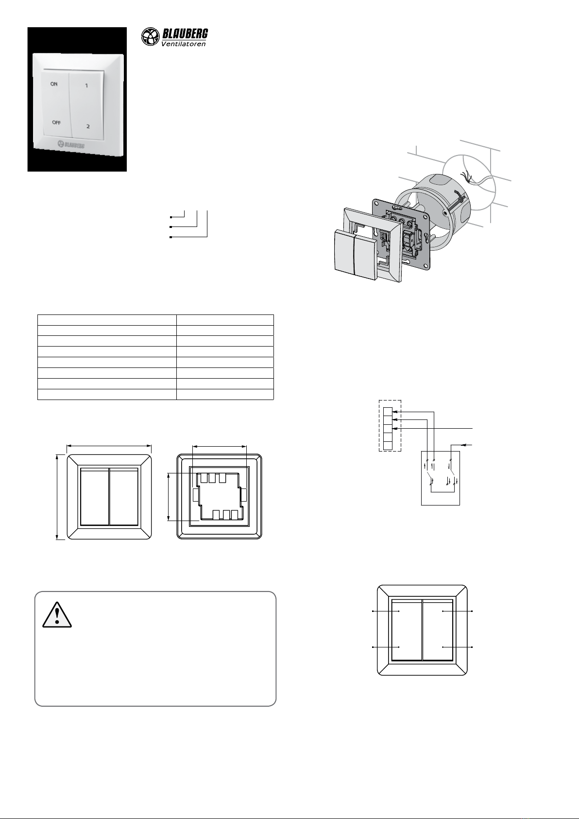
manuals.online logo
Brands
  1. Home
  2. •
  3. Brands
  4. •
  5. BLAUBERG Ventilatoren
  6. •
  7. Switch
  8. •
  9. BLAUBERG Ventilatoren CDP-2/10 User manual

BLAUBERG Ventilatoren CDP-2/10 User manual

Speed switch CDP-2/10
PURPOSE
Applied in ventilation systems for turning
the fans on/o and speed switch of multi-
speed fan motors.
DELIVERY SET
Speed switch 1 pc.
User’s manual 1 pc.
Packing box 1 pc.
CDP-2/10
Speed switch
Two speeds
Maximum load current [A]
TECHNICAL DATA
External parts of the switch are made of non-combustible high impact ABS
plastic. Operating mechanism of the switch is equipped with screw contacts.
Screws with combination heads for use with a standard or a cross screwdriver.
Maximum supply voltage [V] 250
Maximum load current [A] 10
Cable cross section [mm2] from 0.35 up to 0.75
Temperature range [°C] from -10 up to +45
Humidity range [%] 5 - 80 (no condensation)
Service life 1 000 000 switching operations
Electrical protection class IP40
Weight [g] 98
OVERALL AND CONNECTING DIMENSIONS
80.5
80.5
ON
OFF
1
2
52
46
INSTALLATION
MOUNTING AND CONNECTION OF THE ELECTRICAL
EQUIPMENT SHOULD BE PERFORMED ONLY WHEN THE POWER
SUPPLY IS SWITCHED OFF.
ALL THE OPERATIONS WITH THE SPEED SWITCH MUST BE
PERFORMED BY QUALIFIED ELECTRICIANS WITH A WORK
PERMIT FOR ELECTRIC OPERATIONS AND AFTER CAREFUL
READING OF THE USER’S MANUAL.
ANY INTERNAL CONNECTION MODIFICATIONS ARE NOT
ALLOWED AND RESULT IN WARRANTY LOSS.
CAUTION!
Makes sure that the switch is intact. Do not use damaged speed switches.
Do not mount the speed switch onto an uneven surface.
While tightening the self-tapping screws do not apply excessive force to
prevent speed controller casing deformation.
The speed switch is mounted into the mounting box using screws or fixing
lugs. A mounting box and fasteners are not included in the delivery set.
Mounting of the speed switch:
1. Make a niche in the wall for mounting of the speed switch, route the
necessary wires and cables to the mounting place. Insert the mounting box
in the niche.
2. Use a screwdriver to carefully remove the buttons.
3. Unlatch and remove the frame of the control unit.
4. Install the speed switch into the niche in the wall.
5. Install the frame and the buttons in the reverse order.
CONNECTION
CAUTION! To avoid damaging the speed switch, prevent it from being
overloaded. The maximum permissible load current is shown in the «Technical
data» section. Protect the speed switch casing from ingress of foreign objects.
Check the contact arrangement before connecting the unit.
Connect the speed switch according to the wiring diagram:
L1
L2
N
L
N
L2
L1 L3
CONTROL
The two speed fan can be manually switched ON to one of the two required
speeds or switched OFF using the speed switch buttons.
ON
OFF
1
2
First
speed
Second
speed
ON
OFF
SPEED SWITCH CDP2/10
is recognized as serviceable.
Quality Inspector’s Stamp Manufacture Date __________________________________________
Seller
Name of retail company, stamp of the shop______________________________________________________________________________
_________________________________________________________________________________________________________________
Purchase Date________________________________
STORAGE AND TRANSPORTATION REGULATIONS
Store the unit in the manufacturer’s original packing box in a dry closed
ventilated premise with temperature range from +5 °C to + 40 °C.
Storage environment must not contain aggressive vapours and chemical
mixtures provoking corrosion, insulation, and sealing deformation.
Use suitable hoist machinery for handling and storage operations to prevent
possible damage to the unit.
Follow the handling requirements applicable for the particular type of cargo.
The unit can be carried in the original packaging by any mode of transport
provided proper protection against precipitation and mechanical damage.
Avoid sharp blows, scratches, or rough handling during loading and unloading.
MANUFACTURER’S WARRANTY
The manufacturer hereby warrants normal operation of the unit for 12 months
after the retail sale date provided the user’s observance of the transportation,
storage, installation, and operation regulations.
Should any malfunctions occur in the course of the unit operation through
the Manufacturer’s fault during the guaranteed period of operation the user is
entitled to elimination of faults by the manufacturer by means of warranty repair
at the factory free of charge.
The warranty repair shall include work specific to elimination of faults in the unit
operation to ensure its intended use by the user within the guaranteed period of
operation.
The faults are eliminated by means of replacement or repair of the unit
components or a specific part of such unit component.
The warranty repair does not include:
• routine technical maintenance
• unit installation/dismantling
• unit setup
To benefit from warranty repair the user must provide the unit, the user’s manual
with the purchase date stamp and the payment document certifying the
purchase. The unit model must comply with the one stated in the user’s manual.
Contact the Seller for warranty service.
The manufacturer’s warranty does not apply to the following cases:
• User’s failure to submit the unit with the entire delivery package as stated
in the user’s manual including submission with missing component parts
previously dismounted by the user.
• Mismatch of the unit model and the brand name with the information
stated on the unit packaging and in the user’s manual.
• User’s failure to ensure timely technical maintenance of the unit.
• External damage to the unit casing (excluding external modifications as
required for installation) and internal components caused by the user.
• Redesign or engineering changes to the unit.
• Replacement and use of any assemblies, parts and components not
approved by the manufacturer.
• Unit misuse.
• Violation of the unit installation regulations by the user.
• Violation of the unit control regulations by the user.
• Unit connection to power mains with a voltage different from the one
stated in the user’s manual.
• Unit breakdown due to voltage surges in power mains.
• Discretionary repair of the unit by the user.
• Unit repair by any persons without the manufacturer’s authorization.
• Expiration of the unit warranty period.
• Violation of the unit transportation regulations by the user.
• Violation of the unit storage regulations by the user.
• Wrongful actions against the unit committed by third parties.
• Unit breakdown due to circumstances of insuperable force (fire, flood,
earthquake, war, hostilities of any kind, blockades).
• Missing seals if provided by the user’s manual.
• Failure to submit the user’s manual with the unit purchase date stamp.
• Missing payment document certifying the unit purchase.
FOLLOWING THE REGULATIONS STIPULATED HEREIN
WILL ENSURE A LONG AND TROUBLEFREE OPERATION OF
THE UNIT.
USERS’WARRANTY CLAIMS SHALL BE SUBJECT TO
REVIEW ONLY UPON PRESENTATION OF THE UNIT, THE
PAYMENT DOCUMENT AND THE USER’S MANUAL WITH
THE PURCHASE DATE STAMP.
THE PRODUCT MUST BE DISPOSED SEPARATELY AT THE END
OF ITS SERVICE LIFE.
DO NOT DISPOSE THE UNIT AS UNSORTED MUNICIPAL
WASTE.
www.blaubergventilatoren.de
B124EN-02

Other BLAUBERG Ventilatoren Switch manuals

BLAUBERG Ventilatoren CDPE-2 E5 User manual

BLAUBERG Ventilatoren

BLAUBERG Ventilatoren CDPE-2 E5 User manual

BLAUBERG Ventilatoren CDP-3/5 User manual

BLAUBERG Ventilatoren

BLAUBERG Ventilatoren CDP-3/5 User manual

Popular Switch manuals by other brands

Balluff BNI IOL-302-002-E012 user guide

Balluff

Balluff BNI IOL-302-002-E012 user guide

DecorQuip DREAM 191685 quick start guide

DecorQuip

DecorQuip DREAM 191685 quick start guide

Southern States EC-2 Installation instructions manual

Southern States

Southern States EC-2 Installation instructions manual

Divus Heartbeat quick start guide

Divus

Divus Heartbeat quick start guide

ADTRAN Total Access 1210 overview

ADTRAN

ADTRAN Total Access 1210 overview

Cisco Linksys SGE2000P manual

Cisco

Cisco Linksys SGE2000P manual

D-Link DES-1100-10P manual

D-Link

D-Link DES-1100-10P manual

Vivotek AW-GEV-104A Series User manual and warranty statement

Vivotek

Vivotek AW-GEV-104A Series User manual and warranty statement

Extron electronics SW6 HDMI Setup guide

Extron electronics

Extron electronics SW6 HDMI Setup guide

Nortel Passport 15000 Hardware Installation and Maintenance

Nortel

Nortel Passport 15000 Hardware Installation and Maintenance

FS S5850-24XMG-U Series quick start guide

FS

FS S5850-24XMG-U Series quick start guide

Russound A-BUS A-H484 instruction manual

Russound

Russound A-BUS A-H484 instruction manual

NETGEAR GS748T - ProSafe Smart Switch Hardware installation guide

NETGEAR

NETGEAR GS748T - ProSafe Smart Switch Hardware installation guide

Lindy 32901 Installation and use

Lindy

Lindy 32901 Installation and use

Parvus DuraNET 10-10 user manual

Parvus

Parvus DuraNET 10-10 user manual

Honeywell RXSW100A3CULH owner's manual

Honeywell

Honeywell RXSW100A3CULH owner's manual

EUCHNER CES-AR-C01 Series operating instructions

EUCHNER

EUCHNER CES-AR-C01 Series operating instructions

Kramer DIP-22 quick start guide

Kramer

Kramer DIP-22 quick start guide

manuals.online logo
manuals.online logoBrands
  • About & Mission
  • Contact us
  • Privacy Policy
  • Terms and Conditions

Copyright 2025 Manuals.Online. All Rights Reserved.