Voith CTO-B45202 Parts list manual

Instruction and Operating Manual
Overspeed Protector CTO-B45202
2019 / 02
J.M. Voith SE & Co. KG │ Division Digital Ventures
Page: 1 / 25
918 3626018864 en
D – 74564 Crailsheim
Version: 2.1
7
Overspeed Protector
Type: CTO-B45202
Translation of the Original version
Instruction and Operating Manual
Version 2.1
ATTENTION!
Please make sure to read this instruction manual prior to transport, installation,
commissioning, operation, etc. and keep it for further use!

Instruction and Operating Manual
Overspeed Protector CTO-B45202
2019 / 02
J.M. Voith SE & Co. KG │ Division Digital Ventures
Page: 2 / 25
918 3626018864 en
D – 74564 Crailsheim
Version: 2.1
Should you have any questions concerning the
overspeed protector, please contact J.M. Voith SE & Co.
KG, Crailsheim, After-Sales Service of Product Group
Division Digital Ventures in Crailsheim, indicating the
article number and the serial number of the overspeed
protector.
J.M. Voith SE & Co. KG
P.O. Box 15 55
D-74555 Crailsheim
Switchboard: +49 (0) 7951 / 32 - 0
Fax No.: +49 (0) 7951 / 32 - 500
After-Sales Service of Product Group
Division Digital Ventures
Direct dial: +49 - 7951 / 32 - 470
Direct fax: +49 - 7951 / 32 - 605
Email: turcon@voith.com
Address for deliveries of goods:
Voith Group │ Division Digital Ventures
J.M. Voith SE & Co. KG
Voithstraße 1
D-74564 Crailsheim
This instruction manual describes the design standard of
overspeed protector type SMR A45202 with delivery as of
2019 / 02.
J.M. Voith SE & Co. KG 2019
This Instruction Manual is protected by copyright laws. It
must not be translated, duplicated (mechanically or
electronically) in whole or in part, or passed on to third
parties without the publisher's written approval.
Established/revised: 2019 / 02
Order No.: 9183626018864 en
Version: 2.1
Printed in Germany

Instruction and Operating Manual
Overspeed Protector CTO-B45202
2019 / 02
J.M. Voith SE & Co. KG │ Division Digital Ventures
Page: 3 / 25
918 3626018864 en
D – 74564 Crailsheim
Version: 2.1
Contents
Instruction and Operating Manual
Page
1Technical Data ............................................................................................................................... 4
2Safety information......................................................................................................................... 6
2.1 Definition of symbols and warnings ......................................................................................... 6
2.2 Proper use................................................................................................................................ 6
2.3 Important information............................................................................................................... 6
2.4 Warranty................................................................................................................................... 8
3Function.......................................................................................................................................... 9
3.1Mechanical design ................................................................................................................... 9
3.2 Operation ............................................................................................................................... 10
3.3 Trip criteria............................................................................................................................. 10
4Packing, Storage, and Transportation....................................................................................... 12
5Installation.................................................................................................................................... 13
5.1 Mounting ................................................................................................................................ 13
5.2 Hydraulic connection.............................................................................................................. 14
5.3 Electrical Connection ............................................................................................................. 14
6Adjustments and Commissioning ............................................................................................. 15
6.1 Adjustment of turbine trip frequency...................................................................................... 15
6.2 Adjustment of UF- and If-potentiometers............................................................................... 18
7Maintenance and Repair ............................................................................................................. 22
8Decommissioning........................................................................................................................ 23
9Annex............................................................................................................................................ 24
Instruction and Operating Manual
Overspeed Protector CTO-B45202
2019 / 02
J.M. Voith SE & Co. KG │ Division Digital Ventures
Page: 4 / 25
918 3626018864 en
D – 74564 Crailsheim
Version: 2.1
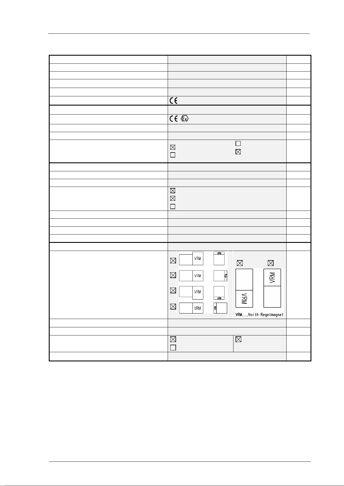
1 Technical Data
Overspeed protector type CTO-B45202
Article number
91868550
Instruction Manual No. 918 3626018864
Product identification
See nameplate
EC Declaration of Conformity
See separate document
EC marking
Protection IP 65 as per EN 60529
Explosion protection
II 2G IIC T4
Ambient temperature T
A
(operation)
-30 ... +60
°C
Ambient temperature (storage) -40 ... +90
Installation conditions Indoor installation
Outdoor installation
Offshore
Industr.
atmosph.
Hydraulic Data
Supply pressure Pmax 25 bar
Operating medium
Type Hydraulic oil as per DIN 51524
Turbine oil as per DIN 51515
High-flash point fluid1)
Oil temperature during operation
+10 … +60
°C
Cleanliness grade (ISO VG 4406)
- / 16 / 13
Viscosity (DIN 51519) ISO VG 32 … ISO VG 46
Leakage (Toil = 50 °C and P=10 bar)
< 2
l/min
Mechanical Data
Installation positions
Dimensions, fastening
See Chapter 9
Hydraulic connection
See Chapter 9
Sealing material
FPM2)
Special design4)
NBR3)
Weight approx. 14 kg
1) According to customer's request or especially for high-flash point fluids
2) Fluor-caoutchouc
3) Acrylnitril-Butadien-caoutchouc
4) according to the customer's specification and consultation with J.M. Voith SE & Co. KG │ Division Digital Ventures

Instruction and Operating Manual
Overspeed Protector CTO-B45202
2019 / 02
J.M. Voith SE & Co. KG │ Division Digital Ventures
Page: 5 / 25
918 3626018864 en
D – 74564 Crailsheim
Version: 2.1
Electrical Data
Supply voltage (power) including residual ripple 24 (+10% / -15%)
5)
V DC
Current consumption
0.5 A±0.2A, max. 3 A for t < 1.5±0.5 sec
Trip-stop frequency fss 4000…10000Hz adjustable in 256 steps,
accuracy 0.25%6) , nameplate, temperature error
120ppm/K
Actual speed remote indication
4…20mA, for f=0… f
ss
Speed input Connect an inductive speed sensor, preferably
sinusoidal voltage, permissible voltage range
0.5Vrms...18Vrms (when connected), permissible
internal resistance range 600Ω…4500Ω7)
Other data
Function - Trip Simulation (partial stroke
check)
Disconnecting time with Potentiometer T4
10ms…25ms
Trip time of overspeed shutdown 40ms at Toil<40°C
8)
Trip criteria See Chapter 3.4
5) Permanent operation of CTO is allowed within this supply voltage range
6) The indication refers to the trip frequency re-measured after the adjustment, as shown on the nameplate.
7) Thei DC voltage resulting depends on the internal resistance of the speed sensor. For an internal resistance of 1000 Ω,
the DC offset voltage is 1.65V ±0.15V.
8) The tripping time is the time required by the control piston to move to its completely open position (end stop) after the
shutdown incident occurred, including a dead time of approx. 10ms. On account of the damping of the movement caused by
the pressure medium, the tripping time depends on the viscosity of the pressure medium. It can be determined by recording
the stroke of the trip-stop valve. When the trip-stop valve moves with constant speed after a trip-top initiation, them the
control piston of the CTO has reached its end position.
Instruction and Operating Manual
Overspeed Protector CTO-B45202
2019 / 02
J.M. Voith SE & Co. KG │ Division Digital Ventures
Page: 6 / 25
918 3626018864 en
D – 74564 Crailsheim
Version: 2.1
2 Safety information
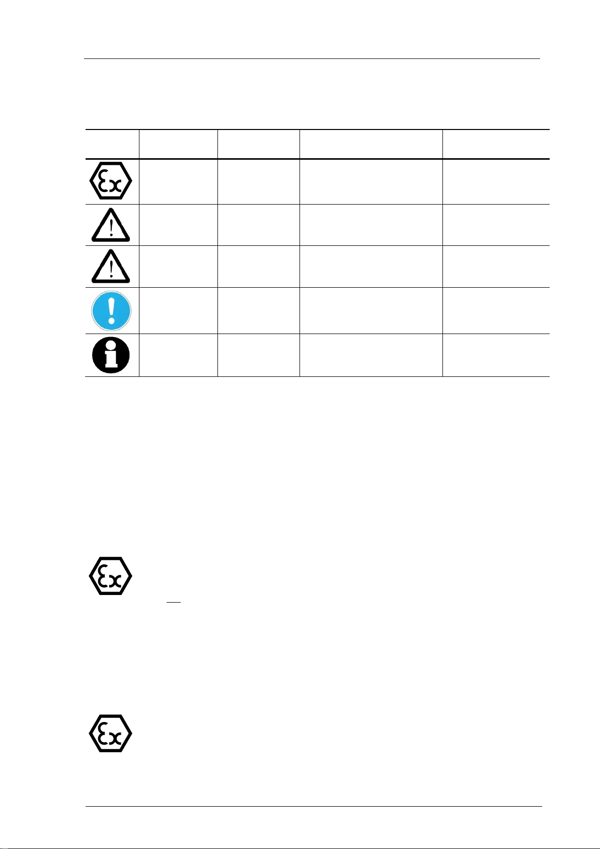
2.1 Definition of symbols and warnings
Symbol Damage/harm
to ... Signal word Definition Consequences
Persons
Property EX-
PROTECTION! Notes to
Ex-protection
Explosion hazard
Persons DANGER! Imminent danger Fatal or most serious
injuries (crippling)
Persons WARNING! Dangerous situation possible Fatal or most serious
injuries possible
Material ATTENTION! Harmful situation possible Possible damage to
- the product
- its environment
– Note!
Information! Application details and other
useful information Efficient in operation
2.2 Proper use
The overspeed protector is an electro-hydraulic turbine trip device to control the speed of
steam turbines. If a trip criterion occurs, the magnetic force is switched off in the electronic
component thus switching over the 3/2-way valve via a restoring spring designed with
substantial power reserves. This procedure reliably connects the way valve outlet with the
tank return line and the trip-stop valve will close. The overspeed protector is suitable for
use in Zone 1 and Zone 2 in potentially explosive atmosphere. Allowable ambient
temperature for operation is
-30°C…..+60°C.
The permissible temperature of the hydraulic oil is +10 °C … +60 °C.
The max. surface of the device is significantly determined by the temperature of the
hydraulic oil.
For the operation it is therefore vital to ensure that the max. permissible oil temperature
will not be exceeded!
2.3 Important information
The following information refers to the entire instruction manual and is to be observed in
addition to the individual instructions.
Accident prevention
It is imperative to observe the requirements of the relevant standards and regulations
when connecting an overspeed protector in explosion-proof design.
There must not be any potentially explosive atmosphere during all works performed,
such as e.g. transportation, storage, installation, electrical connection, commissioning,
test run, maintenance and servicing!

Instruction and Operating Manual
Overspeed Protector CTO-B45202
2019 / 02
J.M. Voith SE & Co. KG │ Division Digital Ventures
Page: 7 / 25
918 3626018864 en
D – 74564 Crailsheim
Version: 2.1
On commissioning or operation of the overspeed protector, spraying hydraulic oil may
get into the eyes causing blindness. Wear protective glasses for all works performed on
the overspeed protector.
The overspeed protector is a hydraulic unit. In case of improper use, operating medium
being under pressure may leak out. Any improper use may lead to the leakage of
operating medium under pressure, posing a risk to the health and life of the operating
staff. Prior to performing any work on the overspeed protector, switch off the hydraulic
supply system.
During operation, the outer surfaces of the overspeed protector and the hydraulic
connecting lines may become hot due to the operating medium. Any contact may cause
injuries by burning. Prior to performing any work on the overspeed protector, let the
overspeed protector cool down.
On commissioning or operation of the overspeed protector, the end of the piston rod
may move uncontrolled in case of failure of the hydraulic or electric energy, due to
malfunctions in the master control or on the overspeed protector. This movement may
pose a risk to both individuals and objects. Prior to performing any work on the
overspeed protector, switch off the hydraulic and electric auxiliary energy.
Electric components
are integrated in the overspeed protector which may be destroyed,
e.g. during electric welding near the overspeed protector. Prior to performing electric
welding near the overspeed protector, remove all electric connecting lines.
Environmental protection
On assembly, disassembly or improper use of the overspeed protector, operating
medium may leak out. Operating medium getting into the sewage system or open soil
causes severe environmental damages. Collect any leaking operating medium and
dispose of it in accordance with the national statutory provisions.
Painting
In case of repaints or mendings of the paint on a device, please ensure that the
maximal permissible total film thickness will not be exceeded. For devices of Gas
Groups IIA and IIB, it is 2 mm and for devices of Gas Group IIC it is 0.2 mm.
Instruction Manual
The instruction manual contains important information regarding proper handling of the
overspeed protector. Prior to installation and commissioning of the overspeed protector,
carefully read the entire instruction manual and make sure you fully understood its
content.
Keep the instruction manual in a place constantly accessible to the operating staff.
In addition to this instruction manual, have the rules governing accident prevention and
environmental protection available and observe same.
Please keep for later reference.

Instruction and Operating Manual
Overspeed Protector CTO-B45202
2019 / 02
J.M. Voith SE & Co. KG │ Division Digital Ventures
Page: 8 / 25
918 3626018864 en
D – 74564 Crailsheim
Version: 2.1
Staff qualification
Only trained and instructed personnel are allowed to work on the overspeed protector.
These personnel must be sufficiently trained, instructed and authorized to properly
mount, operate and maintain the overspeed protector in accordance with the safety
standards.
Installation, commissioning and operation have to be performed by a certified electrician
with experience and knowledge in the field of explosion protection.
Constructional modifications
Mounting work and structural modifications are not permitted.
The screw fitting of the cable entry on the control magnet (VRM) is secured against
distortion. Do not distort or slacken the screw fitting.
2.4 Warranty
The terms and conditions mentioned in the General Terms and conditions for Sale of
Industrial Engineering of J.M. Voith SE & Co. KG │ Division Digital Ventures, Crailsheim
shall apply. Warranty claims are excluded if these are due to one or several of the following
causes:
•Improper transportation, storage, installation, connection, commissioning, operation,
maintenance and repair of products of the overspeed protector.
•Failure to observe the operational and product safety regulations included in this
instruction manual.
•Use of spare parts not approved by J.M. Voith SE & Co. KG │ Division Digital Ventures,
Crailsheim.
During the warranty period, repair work on the overspeed protector may only be
performed with the approval of J.M. Voith SE & Co. KG │ Division Digital Ventures,
Crailsheim.

Instruction and Operating Manual
Overspeed Protector CTO-B45202
2019 / 02
J.M. Voith SE & Co. KG │ Division Digital Ventures
Page: 9 / 25
918 3626018864 en
D – 74564 Crailsheim
Version: 2.1
3 Function
3.1 Mechanical design
Fig. 1: Sectional view of overspeed protector
The overspeed protector consists of the main functional units:
(1) Control magnet VRM P - supply pressure
(2) Tappet for power transmission A - output
(3) Potentiometer T4 T - Tank return line
(4) Electrical connection
(5) Control housing
(6) Control piston FMag - Magnetic force
(7) Restoring spring FF- Federkraft
(8) Cover
(9) Potentiometer Uf
(10) Potentiometer If
(11) 8-fold coding switch
(12) Sealing - electronic compartment cover
(13) Sealing - pole pipe
(14) O-ring for the VRM
(15) O-ring in the potentiometer cover

Instruction and Operating Manual
Overspeed Protector CTO-B45202
2019 / 02
J.M. Voith SE & Co. KG │ Division Digital Ventures
Page: 10 / 25
918 3626018864 en
D – 74564 Crailsheim
Version: 2.1
Block diagram - Overspeed Protector
Turcon®CTn
control
valve
trip-stop valve
reset
external trip
+24VDC
trip sim.
CTo
FMag
K
k
actual speed
0V
turbine
T
T P
A
mA
Fig. 2: Block diagram of the overspeed protector
3.2 Operation
A 3/2-way valve and the control magnet VRM with integrated electronics are the main
components of the overspeed protector CTO.
If no trip criteria exist, the CTO can be switched on via a reset. On doing so, relay K is
energized and thus contact k is closed. An inherently short-circuit-proof holding current
from the VRM keeps relay K energized via the closed-circuit arrangement (e.g. external
trip).
For a limited time (1.5 sec. ± 0.5 sec.), the reset actuates a maximum coil current which
generates a magnetic force FMag and adjusts the piston of the 3/2-way valve against the
progressively designed restoring spring. The coil current is then reduced and the control
piston is kept in its position. Now the supply pressure is connected with outlet A and the
trip-stop valve moves to the "OPEN" position.
In case of a trip criterion (e.g. reaching of the turbine trip frequency), the coil current in the
VRM and the magnetic force FMag become zero. The spring force FF now moves the
control piston in that position where outlet A is connected with the tank return line T.
The trip-stop valve moves into "CLOSED" position.
3.3 Trip criteria
•Wire breakage and / or short circuit on the speed sensor (for limit value, see Chapter 1,
Electrical data, speed input)
•Exceeding the set trip frequency (see Chapter 9, Table 1, Adjusting values - trip
frequency)
•Interruption of the closed-circuit arrangement (e.g. external trip) (see Fig. 2)
•Short circuit at the holding current output (+24 V towards relay)
•Temperature in the electronic compartment of the VRM ≥80 °C

Instruction and Operating Manual
Overspeed Protector CTO-B45202
2019 / 02
J.M. Voith SE & Co. KG │ Division Digital Ventures
Page: 11 / 25
918 3626018864 en
D – 74564 Crailsheim
Version: 2.1
•Power supply >30 V (overvoltage triggering at 29.5V - 32V)
(this criterion is omitted for Article No. TCR.9186855001)
•Power supply <18 V (under voltage at 16-18V)
(this criterion is omitted for Article No. TCR.9186855001)
•Trip simulation = partial stroke test - trip-stop valve
The "trip simulation" does not cause a real turbine trip but the internal release frequency
threshold is reduced for a short time whereas the CTO is released internally for this
time, and thus a tiny movement of the trip-stop cylinder can be seen. The internal
release is not signalled outwards and thus, no real shutdown is activated externally.
The trip simulation allows a functional test of the trip-stop valve during operation when the
turbine speed is greater than/equal to 23% (+0%, -10%) of the set trip frequency. Only then
the CTO can be released internally.
If a trip criterion causes a real turbine trip, the turbine speed has to fall below a reclosure
limit equivalent to max. 55% of the set trip frequency. Only then the CTO can be restarted.

Instruction and Operating Manual
Overspeed Protector CTO-B45202
2019 / 02
J.M. Voith SE & Co. KG │ Division Digital Ventures
Page: 12 / 25
918 3626018864 en
D – 74564 Crailsheim
Version: 2.1
4 Packing, Storage, and Transportation
Packing
The overspeed protector is supplied in a special packaging. All hydraulic connections are
sealed with protective plugs.
Storage and preservation
The outer surfaces of the overspeed protector are electro-plated. On delivery, the inner
parts of the overspeed protector, which are not surface-coated, are moistened with
preservation oil.
Within Europe, this preservation is sufficient as corrosion protection for about 8 months,
provided the overspeed protector is stored in a dry location.
If it is intended to store the overspeed protector for a longer period of time, special
precautions have to be taken. Coordinate such precautions for each individual case with
J.M. Voith SE & Co. KG │ Division Digital Ventures, Crailsheim.
The ambient conditions for storage must be within the limits indicated in Chapter 1.
Transportation
It is not allowed to transport the overspeed protector in an explosive atmosphere! This
also applies to the transportation of spare parts!
Improper transportation or lifting of the overspeed protector may cause damage to
property and personal injuries.
Observe, in particular, that constraining forces do not act on the cable entry of the
control magnet (VRM) and that the connecting line is not damaged.
For transportation purposes, it is not allowed to keep the overspeed protector
connected to the connecting line.

Instruction and Operating Manual
Overspeed Protector CTO-B45202
2019 / 02
J.M. Voith SE & Co. KG │ Division Digital Ventures
Page: 13 / 25
918 3626018864 en
D – 74564 Crailsheim
Version: 2.1
5 Installation
Installation and operation of the overspeed protector is only allowed for the conditions
stated in Chapter 1.
Do not install the overspeed protector in an explosive atmosphere!
During operation, explosive atmosphere may get into the way valve via the tank.
Therefore, the hydraulic tank must not be set up in zone 0.
Only personnel satisfying the qualifications according to Chapter 2.3 are allowed to
work on the overspeed protector.
Improper installation of the overspeed protector may cause malfunctioning and
premature failure of the overspeed protector.
Cleanliness is imperative during
both installation and connection. Prevent any impurities
(dust, metal chips, etc.) from getting into the interior of the overspeed protector or into
the piping system. Any such impurities may cause damage to the overspeed protector.
During the installation period, cover and protect the overspeed protector and, in
particular, the electric and hydraulic connections.
5.1 Mounting
Any work on the overspeed protector may only be performed in de-energized condition
and with the oil supply system switched off. During installation, the oil and power supply
for the overspeed protector has to be secured against unintentional switching-on.
Mount the overspeed protector according to the permissible installation position.
Recommended fastening bolts
2 socket head screws M12, ISO 4762, property class 8.8
Tightening torque MA = 60 Nm, thread oil-moistened.
Select the screw length according to the installation situation.

Instruction and Operating Manual
Overspeed Protector CTO-B45202
2019 / 02
J.M. Voith SE & Co. KG │ Division Digital Ventures
Page: 14 / 25
918 3626018864 en
D – 74564 Crailsheim
Version: 2.1
5.2 Hydraulic connection
Flanging of the overspeed protector to a hydraulic consumer is effected via connecting
bores at the overspeed protector bottom.
O-rings are used for sealing the connecting flange.
For position and dimensions of the connections, please see Chapter 9.
Wear protective glasses when connecting the overspeed protector hydraulically.
Pay attention to the correct pressure stage when selecting pipes, flexible tubes, unions,
and flanges.
Immediately replace any damaged pipes and flexible tubes.
When assembling the pipes, ensure that they are not fastened to any moving equipment,
but rather to fixed structures free from vibration.
Alterations in length caused by temperature variations must not apply constraining forces
to the overspeed protector.
Fixing and hydraulic connection to a connecting flange is made via the hydraulic part.
O-rings are used for sealing. The customer's connecting surface has to correspond to
Ra ≤ 1.6 µm and Rmax ≤ 6.3 µm.
Residual oil (up to 0.2 l) may leak out when removing the screw plugs. Collect the oil in
a suitable container and dispose of it properly.
Do not use fibrous or hardening sealing compounds, such as hemp or mastic, for
sealing the connections and pipe unions.
5.3 Electrical Connection
For wiring diagram, see Chapter 9.
Only a certified electrician with experience and knowledge in the field of explosion
protection is allowed to connect the way valve module electrically in accordance with
the electro-technical rules and legal provisions of the country of manufacture. When
connecting the overspeed protector within the explosion hazardous area, the electric
feed-in lines have to be connected in housings according to a standard type of
protection as per EN 60079-0, section 1.
Work on the electrical system or with operational equipment is only to be completed by
electrical technicians or by trained personnel under the guidance and supervision of an
electrical technician according to technical electrical regulations and the legal
regulations of the respective country.
Signal and supply lines provided by the customer to the overspeed protector need to be
screened and laid separately from each other.
When connecting the customer's lines, please avoid parallel running of lines with the
lines of the current converter assemblies.
Poor connecting points do not guarantee a reliable operation of the overspeed
protector.
Instruction and Operating Manual
Overspeed Protector CTO-B45202
2019 / 02
J.M. Voith SE & Co. KG │ Division Digital Ventures
Page: 15 / 25
918 3626018864 en
D – 74564 Crailsheim
Version: 2.1
6 Adjustments and Commissioning
Prior to delivery, the overspeed protector has been tested and adjusted at
J.M. Voith SE
& Co. KG │ Division Digital Ventures. The settings are documented in the supplied test
report.
6.1 Adjustment of turbine trip frequency
Any trip frequency adjustment represents a potentially dangerous manipulation of the
equipment and only skilled personnel, authorized by
the manufacturer or the supplier, is
allowed to do it. Any maladjustment may cause imminent danger to life and severe
damage to properties. In any case, any adjustment of the turbine trip frequency has to
be documented. Confirmation of the new adjustment by means of a documented trip
test is mandatory before operating the turbine.
For safety reasons, the overspeed protector is set to the minimum trip frequency possible
of approx. 3800 Hz. For the exact value, please see the relevant test report submitted to
you.
The turbine trip frequency is set by means of an 8-fold DIP coding switch which is
protected on the electronics that is integrated in the control mangnet A (VRM) (see Fig. 5).
Fig. 3
Prior to commissioning, please ensure that the pipes and the hydraulic system have
been cleaned. Cleanliness of the operating medium must correspond to the cleanliness
grade stated in Chapter 1. Cleaning and flushing operations essential to the operating
medium must not be performed with the overspeed protector connected. Operation of
the overspeed protector with contaminated operating medium is not permitted and may
damage the overspeed protector.
Instruction and Operating Manual
Overspeed Protector CTO-B45202
2019 / 02
J.M. Voith SE & Co. KG │ Division Digital Ventures
Page: 16 / 25
918 3626018864 en
D – 74564 Crailsheim
Version: 2.1
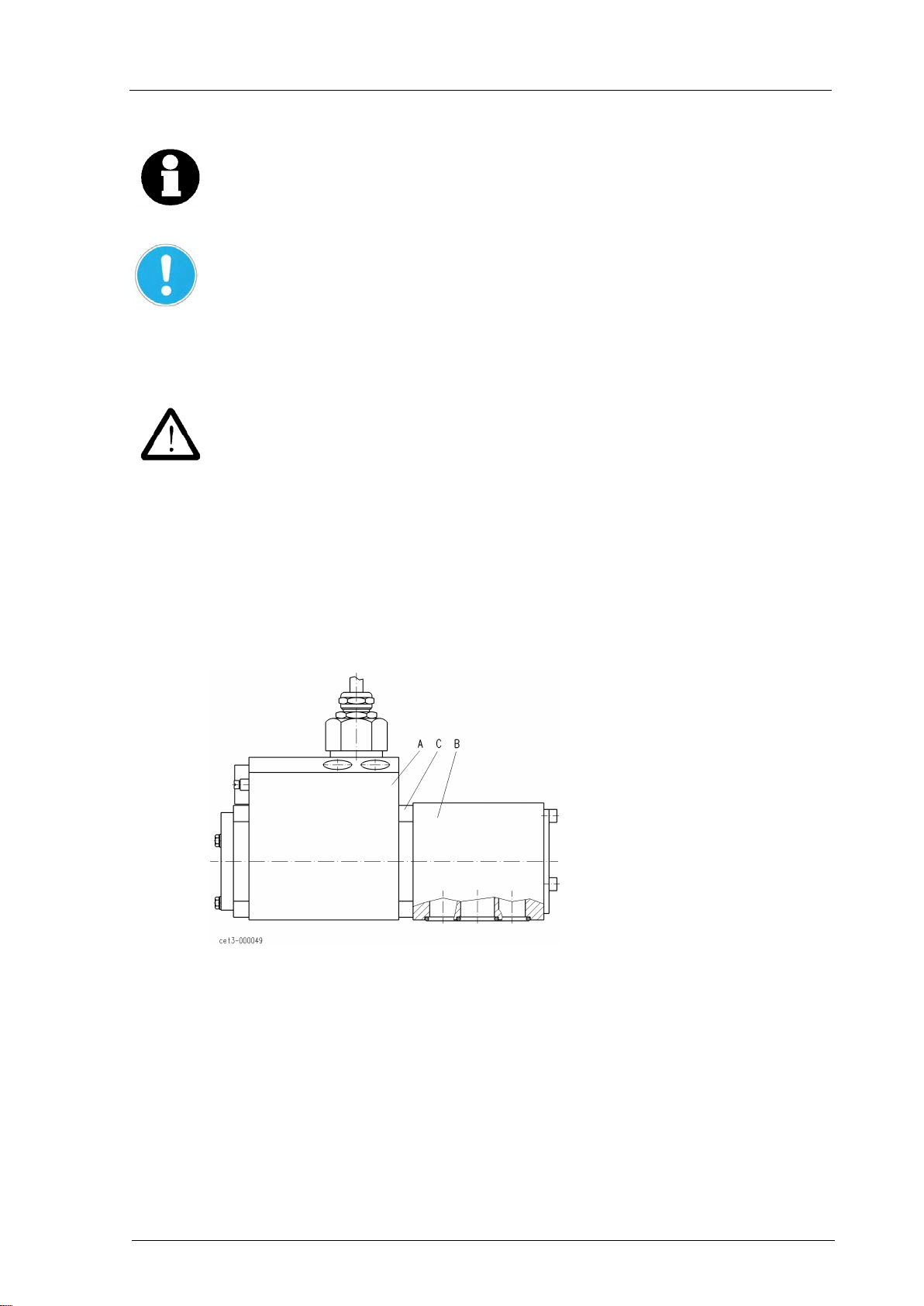
Fig.: 4
Disconnect the VRM from the hydraulic component B in order to get to the coding switch.
To do so, loosen the 4 screw nuts D (10 mm width across flats) and pull off the VRM from
the hydraulic component B.
In the course of the further procedure described, the pressure-tight and explosion-
protected enclosure of the VRM will be opened and explosion protection will no longer
be effective. Therefore, make sure in advance that there is no explosive atmosphere or
may form as long as cover C is not remounted and secured by the screws.
Unscrew the 4 Allan screws (5 mm width across flats) used to fix cover C (see Fig. 3) and
remove the cover. On account of the seal in cover C, it is not easy to move. It may
therefore be helpful to first turn the cover and then lift it using a screwdriver until some air
can get into the electronic compartment underneath. Then it will be easy to remove the
cover.
The cylindrical component (diameter 80 mm) and the bore (diameter 12 mm) of cover C
are part of the pressure-tight, explosion-
protected enclosure and must not be damaged,
as well as the bore and cylinder sections of the magnet housing belonging to these
surfaces. Do not damage the anticorrosion protection of the relevant surfaces. In case
of damaged surfaces or incomplete anticorrosion protection, the explosion protection is
no longer granted and the overspeed protector has to be replaced.
Fig. 5 shows the top view onto the electronics installed underneath cover C with coding
switch SS1 and UF- and If-potentiometers.

Instruction and Operating Manual
Overspeed Protector CTO-B45202
2019 / 02
J.M. Voith SE & Co. KG │ Division Digital Ventures
Page: 17 / 25
918 3626018864 en
D – 74564 Crailsheim
Version: 2.1
Uf If
SS1
ON
12345678
OFF
ON
8 7 6 5 4 3 2 1
VO ITH
E528
Fig.: 5
Shifting the respective individual switch 1 - 8 of SS1 adjusts the required turbine trip
frequency whereas OFF position corresponds to 0 and ON position to 1.
The switch combination to be adjusted is an 8-bit binary number (finary number 0000 0000
to 1111 1111 = decimal number 0-255), calculated as follows, based on the required trip
frequency:
trip frequency [Hz]- 3800 Hz
Decimal number SS1 = −−−−−−−−−−−−−−−−−−−−−−−−−−−
27.333 Hz
Convert this decimal number into a binary number and set it directly as switch combination
at SS1, whereas 1 = ON and 0 = OFF, and also set the least significant number on the
right at switch 1 and the most significant on the left at switch 8.
A more convenient method is to enter into Table 1 attached with the desired trip frequency
and to directly take from there the switch combination to be adjusted.
If you use the actual speed remove indication, readjust the 4 mA value using the If-
potentiometer for speed 0 after adjustment of the trip frequency. See Chapter 6.2, If-
potentiometer.
After setting the coding switches at SS1, remount cover C and fix it using the 4 Allan
screws. Make sure that the O-ring in the cover and the two small O-rings in the pole pipe
are mounted, not damaged and greased (see Fig. 1). Relock the 4 Allan screws using the
circlips.
Now push the VRM onto the hydraulic component, at the control housing of which the O-
ring between the hydraulic component and the VRM has to be mounted correctly.
After the overspeed protector is again ready for operation, a test of the readjusted trip
frequency is mandatory. On account of rounding errors and/or manufacturing tolerances, it
may be necessary to increase or reduce the binary number set by 2. Should this be the
case, please proceed again as outlined above. A trip frequency test has to be performed
and documented at any rate after completion of the settings. This test should be performed
in warm condition (CTO should be operated for about 30 min. at an oil temperature of
approx. 50 °C).
After that, seal the overspeed protector, thus securing the setting.
See section A-A of the outline drawing in Chapter 9, Annex.

Instruction and Operating Manual
Overspeed Protector CTO-B45202
2019 / 02
J.M. Voith SE & Co. KG │ Division Digital Ventures
Page: 18 / 25
918 3626018864 en
D – 74564 Crailsheim
Version: 2.1
6.2 Adjustment of UF- and If-potentiometers
Uf-potentiometer (please see Fig. 5)
The Uf-potentiometer is provided to adjust the turbine trip frequency reference, it is set at
the factory and sealed. Any adjustment is prohibited!
If-potentiometer (please see Fig. 5)
This potentiometer needs to be adjusted only if you want to use the actual speed remote
indication. The limit of 20 mA actual speed remote indication is permenantly assigned to
the turbine trip frequency and is corrected automatically on adjustment of the turbine trip
frequency. The initial value of 4 mA is to be assigned to 0 Hz.
On adjustment of the turbine trip frequency (see Chapter 6.1), however, also the
assignment of 4 mA initial value changes at the same time. It is possible to re-adjust this
4 mA initial value to 0 speed by means of the If-potentiometer. To do so, remove the
locking compound of the If-potentiometer and renew it after the adjustment.
For this purpose, the output of the actual speed remote indication is put on an mA-meter.
At 0 speed, the If-potentiometer is turned until the mA-meter indicated 4.0 mA. Turning the
potentiometer clockwise will increase the mA-signal.
In case of a trip of the CTO, the actual speed remote indication returns to 0 mA due to the
external switch-off of the 24V CTO supply. In case this external switch-off of the 24V
supply is prevented erroneously, the actual speed indication increases to higher values and
the allocation of the speed to the actual speed signal is no longer correct during this state.
After a proper reconnection of the CTO, this state eliminates on its own.
T4-potentiometer (please see Fig. 6 and Fig. 4)
The T4-potentiometer is used to set the trip time of the trip simulation function (partial
stroke test with trip-stop cylinder. The potentiometer is in the VRM and protected by a
cover.
Following the procedure described below, the pressure-tight, explosion protected
enclosure of the VRM will be opened and the explosion protection will no longer be
effective. Therefore, it has to be checked before that there is no explosive atmosphere
or may form as long as cover E is not remounted and secured by screws F.
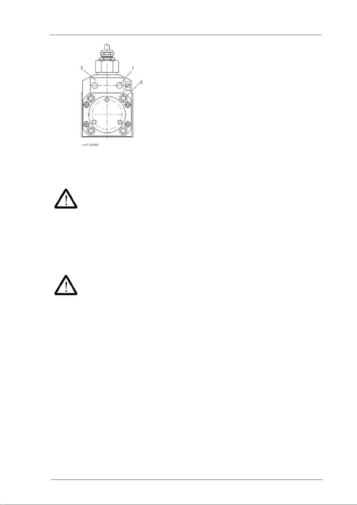
Loosen the 2 Allan screws F (5 mm width across flats, see Fig. 4) in order to get to the T4-
potentiometer. The remove cover E. On account of the O-ring (see Fig. 1) in cover E it
might be somewhat hard to remove it.
The cylindrical part of the cover and the enclosure bore form part of the pressure-tight
enclosure for explosion protection. The cylindrical surface of the cover and the
associated surface of the enclosure bore must not be damaged. The corrosion
protection of these surfaces needs to be completely preserved!
Fig.: 6

Instruction and Operating Manual
Overspeed Protector CTO-B45202
2019 / 02
J.M. Voith SE & Co. KG │ Division Digital Ventures
Page: 19 / 25
918 3626018864 en
D – 74564 Crailsheim
Version: 2.1
Turning the T4-potentiometer will adjust the trip time, elapsing after releasing the "trip
simulation" pushbutton = partial stroke test - trip-stop valve (see Fig. 2, and for functional
description, see Chapter 3.49. Thus, the trip time is adjustable.
The temporary trip time is extended by turning the potentiometer clockwise.
The potentiometer is factory-set to the minimum possible trip time. Repeated pushing and
releasing the pushbutton "trip simulation" adjusts the potentiometer. The potentiometer is
adjusted in steps clockwise and the trip-stop valve is observed. The trip time is set correctly
when the trip-stop valve performs a little stroke towards the closing direction, but does not
yet have a negative influence on the turbine operation.
Doing so, it is possible to check the function of the overspeed protector and trip-stop valve
in intervals to be determined by pushing and releasing the "trip simulation" button during
turbine operation.
After adjustment of the temporary trip time, remount cover E and fix it using the 2 Allan
screws F. Observe that the O-ring is inserted in the cover, undamaged and greased. Lock
the 2 Allan screws using the circlips.
Instruction and Operating Manual
Overspeed Protector CTO-B45202
2019 / 02
J.M. Voith SE & Co. KG │ Division Digital Ventures
Page: 20 / 25
918 3626018864 en
D – 74564 Crailsheim
Version: 2.1
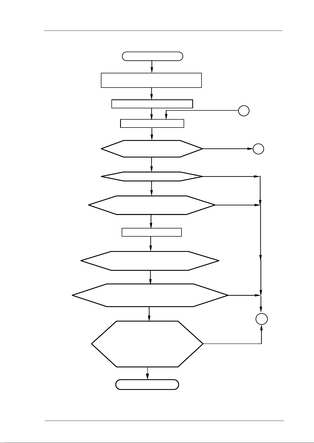
6.3 Commissioning
Commissioning START
Check cables and hydraulic lines
according to wiring diagram
Connect to supply voltage
Press the "Reset button"
Are the trip signals for the
speed controller and for external processing
reset?
Does the hydraulic valve open fully?
Does the hydraulic valve close, the
speed controller signal “trip“ and is the external trip signal
available after opening of external trip loop?
Press the "Reset button"
Disconnection when / on:
-exceeding SS frequency
-external trip loop is interrupted
-overvoltage
-undervoltage
-interruption or short circuit of speed
pick up
-short circuit of coil connections of
external relay K
END of commissioning
Does the stroke of the trip-stop cylinder collapse for a
short time when operating the trip-sim. pushbutton? (you can adjust
the time to trip the overspeed protection by means of the T4
potentiometer see chapter 6.2)
Bring turbine speed close to rated speed
or achieve the same by simulating the
actual speed
no
yes
yes
no
A
yes
yes
C
no
no
no
yes
yes
B
This manual suits for next models
1
Table of contents
Other Voith Industrial Equipment manuals


Popular Industrial Equipment manuals by other brands


Muller
Muller HYDRO-GUARD 300 Series Operating instructions manual

TRAK
TRAK VMC10 Site preparation guide

PCB Piezotronics
PCB Piezotronics IMI SENSORS Spindler Industrial ICP 607A61 Installation and operating manual

Dedoes
Dedoes Alliance A7 Assembly instructions

Huawei
Huawei LUNA2000-97KWH-1H1 quick guide

PCB Piezotronics
PCB Piezotronics 356A01/NC Installation and operating manual