Voith TN Series User manual

Installation and Operating Manual
(Translation of the original installation and operating manual)
T…
Turbo Coupling with Constant Fill
including design as per ATEX directives:
Directive 94/9/EC (valid until April 19, 2016), Directive 2014/34/EU (valid from April 20, 2016)
Version 10 , 2016-01-11
3626-011000 en, Protection Class 0: public
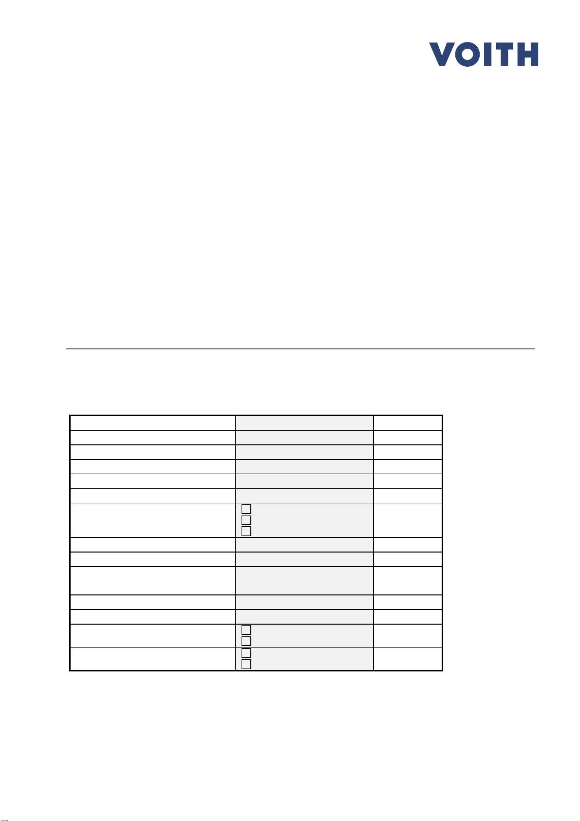
Serial No.
1)
Coupling type
2)
Year of manufacture
Mass (weight)
kg
Power transmission
kW
Input speed
rpm
Operating fluid
mineral oil
water
Filling volume
dm
3
(liters)
Number of screws z
3)
Nominal response temperature of
fusible plugs
°C
Connecting coupling type
Sound pressure level LPA,1m
dB
Installation position
horizontal
vertical
Drive via
outer wheel
inner wheel
1) Please indicate the serial number in any correspondence (Chapter 18).
2) T...: oil / TW...: water.
3) Determine and record the number of screws z (Chapter 10.1).
Please consult Voith Turbo in case that the data on the cover sheet are incomplete.

Installation and Operating Manual / Version 10 / 3626-011000
en / Protection Class
0: public / 2016-01-11
2
Turbo Coupling with Constant Fill
Contact
Contact
Voith Turbo GmbH & Co. KG
Division Mining & Metals
Voithstr. 1
74564 Crailsheim, GERMANY
Tel. + 49 7951 32 409
Fax
+ 49 7951 32 480
startup.components
@voith.com
www.voith.com/fluid
-coupling
3626
-011000 en
This document describes the state of
design of the product at the time of the
editorial deadline on 201
6-01-11.
Copyright © by
Voith Turbo GmbH & Co. KG.
This document is protected by copyright.
It must not be translated, duplicated
(mechanically or elec
tron
ically) in whole
or in part, nor passed on to third parties
without the publisher's written approval.

Installation and Operating Manual / Version 10 / 3626-011000
en / Protection Class
0: public / 2016-01-11
3
Turbo Coupling with Constant Fill
Contents
Contents
1Voith Turbo Coupling with Constant Fill 8
1.1 Function 8
1.2 Type designation 10
1.3 Constructional examples 11
Connecting coupling on the input side 111.3.1
Connecting coupling on the output side 121.3.2
2Technical Data 13
3Tightening Torques 15
3.1 Set screws and fixing bolts 16
3.2 Fusible plugs, filler plugs, sight glasses, blind- and
nozzle screws 16
3.3 Fastening screws 17
4Declarations of Manufacturer 18
4.1 Declaration regarding assemblies and components 18
4.2 Conformity Declaration 19
5User Information 20
6Safety 22
6.1 Safety information 22
Structure of safety information 226.1.1
Definition of safety symbols 236.1.2
6.2 Intended use 23
6.3 Unintended use 24
6.4 Structural modifications 24
6.5 General information as to dangerous situations 24
6.6 Remaining risks 29
6.7 What to do in case of accidents 29
6.8 Information with regard to operation 29

Installation and Operating Manual / Version 10 / 3626-011000
en / Protection Class
0: public / 2016-01-11
4
Turbo Coupling with Constant Fill
Contents
6.9 Qualification of staff 34
6.10 Product monitoring 34
7Transport and Storage 35
7.1 As delivered condition 35
7.2 Scope of supply 35
7.3 Transport 36
7.4 Lifting 37
7.5 Storage / Packing / Preservation 42
Storage of turbo coupling 427.5.1
Storage of flexible element 447.5.2
8Installation and Alignment 45
8.1 Tools 45
8.2 Preparation 46
Keys 478.2.1
8.3 Mounting of basic type T turbo coupling 48
Mounting 488.3.1
Mounting device 528.3.2
8.4 Mounting of basic type TN turbo coupling 53
Mounting 538.4.1
8.5 Alignment 56
Connecting coupling on the input side (outer wheel drive) 568.5.1
Connecting coupling on the output side (outer wheel drive) 588.5.2
Laid lengths and type allocations turbo coupling / flexible8.5.3
connecting coupling 58
Displacement values 608.5.4
Alignment 618.5.5
9Operating fluids 63
9.1 Requirements to be fulfilled by the operating fluid 'mineral oil' 64
Usable operating fluids 649.1.1
Operating temperature frequently above 100 °C 649.1.2
Proposed operating fluids 659.1.3

Installation and Operating Manual / Version 10 / 3626-011000
en / Protection Class
0: public / 2016-01-11
5
Turbo Coupling with Constant Fill
Contents
9.2 Proposed operating fluids for special requirements 66
9.3 Requirements to be fulfilled by the operating fluid 'water' 67
Usable operating fluids 679.3.1
Water used as operating fluid for turbo couplings with9.3.2
centrifugal valves (types TW…F…) 68
10 Filling, Filling Check and Draining 70
10.1 Filling the turbo coupling 71
How to fill turbo couplings installed in horizontal position,10.1.1
inclination < = 30° 71
How to fill turbo couplings installed in vertical position,10.1.2
inclination > 30° 73
10.2 Level check 74
Level check for turbo couplings installed in horizontal position 7410.2.1
Level check for turbo couplings installed in vertical position 7510.2.2
10.3 Draining the turbo coupling 75
Draining of turbo couplings without delay chamber installed10.3.1
in horizontal position 76
Draining of turbo couplings with delay chamber installed10.3.2
in horizontal position 76
How to drain turbo couplings installed in vertical position 7710.3.3
11 Commissioning 78
12 Operation 81
13 Maintenance, Servicing 82
13.1 Outside cleaning 85
13.2 Flexible connecting coupling 86
Checking the flexible element for wear 8613.2.1
Maintenance intervals 8813.2.2
13.3 Bearings 88
Bearing lubrication when mineral oil is used as operating fluid 8813.3.1
Bearing lubrication when water is used as operating fluid 8813.3.2
Replacement of bearings / re-lubrication 8913.3.3

Installation and Operating Manual / Version 10 / 3626-011000
en / Protection Class
0: public / 2016-01-11
6
Turbo Coupling with Constant Fill
Contents
13.4 Fusible plugs 89
Fusible plugs in turbo couplings not suitable for use in13.4.1
potentially explosive atmospheres 90
Fusible plugs in turbo couplings suitable for use in13.4.2
potentially explosive atmospheres 92
14 Assembly Check-, Commissioning and Maintenance Report 94
14.1 Assembly check report 95
14.2 Commissioning report 97
14.3 Maintenance report for general maintenance 99
Maintenance report for flexible connecting coupling 10014.3.1
15 Disassembly of Turbo Coupling 101
15.1 Preparation 101
15.2 Disassembly of basic type T turbo coupling 102
Removal using the hydraulic removal device 10415.2.1
Removal using the mechanical removal device 10515.2.2
15.3 Reassembly of basic type T turbo coupling 107
15.4 Disassembly of basic type TN turbo coupling 107
15.5 Reassembly of basic type TN turbo coupling 107
16 Disposal 108
17 Malfunctions - Remedial Actions 109
18 Queries, Orders Placed for Service Engineers and
Spare Parts 112
19 Temperature monitoring 113
19.1 MTS mechanical thermal switch unit for pre-warning 114
19.2 BTS non-contacting thermal switch unit 115
BTS non-contacting thermal switch unit for pre-warning 11519.2.1
BTS-Ex non-contacting thermal switch unit for limiting the19.2.2
maximum surface temperature 116
19.3 BTS non-contacting thermal measuring device for
pre-warning 117

Installation and Operating Manual / Version 10 / 3626-011000
en / Protection Class
0: public / 2016-01-11
7
Turbo Coupling with Constant Fill
Contents
20 Spare Parts Information 118
20.1 Components overview - Voith turbo coupling 154 – 1150 120
20.2 Spare parts for Voith turbo coupling 154 – 274 121
20.3 Spare parts for Voith turbo coupling 366 – 1150 122
20.4 Spare parts for connecting coupling 124
Connecting coupling on the input side 12420.4.1
Connecting coupling on the output side 12620.4.2
21 Representatives - Voith Turbo GmbH & Co. KG 127
22 Index 132

Installation and Operating Manual / Version 10 / 3626-011000
en / Protection Class
0: public / 2016-01-11
8
Turbo Coupling with Constant Fill
Voith Turbo Coupling with Constant Fill
1 Voith Turbo Coupling with
Constant Fill
1.1 Function
Fig. 1
The Voith turbo coupling is a hydrodynamic coupling working to the Föttinger principle.
Its main elements consist of two blade wheels - the pump impeller and the turbine
wheel - enclosed by a shell. Both wheels are provided with bearings relative to each
other. The power is transmitted with hardly any wear, there is no mechanical contact
between the power-transmitting parts. A constant amount of operating fluid is in the
coupling.
The mechanical energy provided by the drive motor is converted into kinetic energy of
the operating fluid in the connected pump impeller. In the turbine wheel, this kinetic
energy is reconverted into mechanical energy.
Shell
Blade wheels

Installation and Operating Manual / Version 10 / 3626-011000
en / Protection Class
0: public / 2016-01-11
9
Turbo Coupling with Constant Fill
Voith Turbo Coupling with Constant Fill
Three conditions are to be considered with regard to the coupling function:
Fig. 2
Standstill
The whole operating fluid rests in the
coupling.
Fig. 3
Starting condition
The pump impeller accelerates the
operating fluid with increasing motor
speed causing a circulating flow in the
worki
ng chamber. The whole blade
space of the turbine wheel is flooded,
and the turbine wheel starts to move as a
result of the kinetic energy of the fluid
flow. The coupling characteristic curve
determines the torque curve during start-
up.
Fig. 4
Nominal operation
During nominal operation, only the torque
required by the driven machine is
transmitted. The low speed difference
between pump impeller and turbine wheel
(the so-
called rated slip) results in a
stationary flow condition in the coupling.

Installation and Operating Manual / Version 10 / 3626-011000
en / Protection Class
0: public / 2016-01-11
10
Turbo Coupling with Constant Fill
Voith Turbo Coupling with Constant Fill
1.2 Type designation
For hydrodynamic couplings with constant fill, the type designation is determined as
follows:
1
2
3
4
5
6
7
8
9
10
11
12
Example: 562 TVVS03
562
T
VV
S
03
1 Coupling size (profile diameter in mm)
Possible sizes: 154, 206, 274, 366, 422, 487, 562, 650, 750, 866, 1000, 1150
2 Number of hydrodynamic circuits
T: single-circuit coupling
DT: double-circuit coupling
3 Material
"no code letter": Silumin
U: ferrous material
4 Operating fluid
"no code letter": mineral oil
W: water (please consult Voith regarding anti-freezing agent)
5
Delay chamber
"no code letter": without delay chamber
V: with delay chamber
VV: with enlarged delay chamber
6
Draining of delay chamber
"no code letter": time-dependent draining without dynamic refill
F: with centrifugal valves (normally they are open on standstill)
Y: with dynamic refill
7 Shell
"no code letter" standard design
S: designed as annular chamber
8
Turbo coupling connection
"no code letter": designed for flexible connecting coupling mounted on
the outer wheel side
N: designed for primary coupling flange and flexible
connecting coupling mounted on the coupling shaft.
9
Design status
“no code letter“: first design
old: A, B, C, E, G, H, J
new: 01, 02, 03, 04, 05, 06, 07, 08, 09, 10, …
10 Throttle plate
"no code letter": without throttle plate
D: with throttle plate
11
Design
"no code letter": standard design
X: special constructional design
Z: special hydrodynamic design
12 Possible supplementary information in plain text
Type designation
Cover sheet

Installation and Operating Manual / Version 10 / 3626-011000
en / Protection Class
0: public / 2016-01-11
11
Turbo Coupling with Constant Fill
Voith Turbo Coupling with Constant Fill
1.3 Constructional examples
Connecting coupling on the input side1.3.1
Type T (basic type):
Fig. 5
Type TV:
Fig. 6
Type TVV:
Fig. 7
Type TVVS:
Fig. 8
Type DT:
Fig. 9
Type DTV:
Fig. 10

Installation and Operating Manual / Version 10 / 3626-011000
en / Protection Class
0: public / 2016-01-11
12
Turbo Coupling with Constant Fill
Voith Turbo Coupling with Constant Fill
Connecting coupling on the output side1.3.2
Type TN (basic type):
Fig. 11
Type TVN:
Fig. 12
Type TVVN:
Fig. 13
Type TVVSN:
Fig. 14
Design 1
__ _ __ _ __
Design 2
Design 1
__ _ __ _ __
Design 2

Installation and Operating Manual / Version 10 / 3626-011000
en / Protection Class
0: public / 2016-01-11
13
Turbo Coupling with Constant Fill
Technical Data
2 Technical Data
Information required for use in potentially explosive atmospheres:
marking:
Ambient temperature, if deviating from
-25 °C Ta40 °C °C
max. surface temperature
(T3= 200 °C, T4= 135 °C,
or deviating) °C
Temperature monitoring MTS 1) for pre-warning
BTS 2) for pre-warning
BTS-Ex 2) for limitation of max.
surface temperature for Voith turbo
couplings acc. to ATEX Directive.
Maximum permissible temperature
of turbo coupling when switching on
the motor:
°C
Nominal response temperature of
temperature monitoring
°C
Max. permissible filling volume 3) dm3(liters)
Overload (à Chapter 6.8), causing the
thermal fuse (fusible plug/s and/or BTS-
Ex) to respond, requires the power supply
to be switched off after
s (sec)
An additional monitoring of the output
speed is required to switch off the power
supply before the fusible plugs respond.
Yes
No
After switching on the motor, monitoring of
output speed has to begin after
s (sec)
Diameter of input 4) mm
Diameter of output
4)
mm
Replacement of ball and roller bearings
after
h
Table 1
1) MTS: Mechanical thermal switch unit (Chapter 19.1).
2) BTS: Non-contacting thermal switch unit (Chapter 19.2).
3) Applies if filling volume is not indicated on the cover sheet.
4) Diameter and fit of hub or shaft to be joined by means of shaft-hub connection.

Installation and Operating Manual / Version 10 / 3626-011000
en / Protection Class
0: public / 2016-01-11
14
Turbo Coupling with Constant Fill
Technical Data
Additional information/data required for use in potentially explosive atmos-
pheres:

Installation and Operating Manual / Version 10 / 3626-011000
en / Protection Class
0: public / 2016-01-11
15
Turbo Coupling with Constant Fill
Tightening Torques
3 Tightening Torques
NOTICE
Damage to property
The turbo coupling may be damaged by incorrectly tightened screws.
•
Tighten all screws using a torque-adjustable torque wrench!
Fig. 15
1) For arrangement and quantity, Chapter 13.4.
2) From coupling size 366.
Filler plug,
item 0390
Nozzle screw,
item 0455 / 0456
Fastening screw,
item 1830 (for TN: 0780)
Blind screw, item 0394 1)
Fusible plug,
item 0395
1)
Sight glass, item 0396 2)
Set screw,
item 1845
Hex. screw,
item 1870
Fixing bolt,
item 0050
Fusible plug,
item 0260
1)
Blind screw, item 0265 1
)
Fastening screw,
item 1660
Blind screw,
item 0394
Brake drum

Installation and Operating Manual / Version 10 / 3626-011000
en / Protection Class
0: public / 2016-01-11
16
Turbo Coupling with Constant Fill
Tightening Torques
3.1 Set screws and fixing bolts
Tightening torque in Nm
Thread M6 M8 M10 M12 M16 M20 M24 M30 M36 M42
Set screw,
item 1845 4 8 15 25 70 130 - - - -
Fixing bolt,
item 0050 - 23 46 80 195 380 660 1350 2350 3750
Table 2
The tightening torques for set screws apply to property classes as per EN ISO 898-5.
The tightening torques for fixing bolts apply to screws with property class 8.8 or higher
(as per EN ISO 898-1), oil-moistened and relevant shaft journal material.
3.2 Fusible plugs, filler plugs, sight glasses, blind- and
nozzle screws
Tightening torque in Nm
(dimension of thread)
Coup-
ling
size
Fusible plug,
item 0260,
item 0395
Filler plug,
item 0390
Blind
screw,
item 0265,
item 0394
Sight
glass
Pos. 0396
Nozzle
screw,
item 0455,
item 0456
154
8
(M8)
13
(M10)
8
(M8)
- -
206
13
(M10)
20
(M12x1.5)
13
(M10)
- -
274
13
(M10)
30
(M14x1.5)
13
(M10)
- -
366 to
650
50
(M18x1.5)
80
(M24x1.5)
50
(M18x1.5)
50
(M18x1.5)
48
(M16x1.5)
750 to
1150
144
(M24x1.5)
235
(M36x1.5)
144
(M24x1.5)
144
(M24x1.5)
48
(M16x1.5)
Table 3

Installation and Operating Manual / Version 10 / 3626-011000
en / Protection Class
0: public / 2016-01-11
17
Turbo Coupling with Constant Fill
Tightening Torques
3.3 Fastening screws
Tightening torque in Nm
(dimension of thread)
Coupling
size
Fastening
screw,
item 0780,
item 1830
Fastening
screw,
item 1660
Socket head
screw,
Nor-Mex G,
item 1816
2)
Hex. screw,
EPK,
item 1870
154
9
(M6)
- - -
206
23
(M8)
- - -
274
68
(M12)
80
(M12)
- -
366
68
(M12)
80
(M12)
49
(M10)
23
(M8)
422
68
(M12)
80
(M12)
49
(M10)
46
(M10)
487
68
(M12)
80
(M12)
49
(M10)
46
(M10)
562
68
(M12)
195
(M16)
125 1)
(M12)
46
(M10)
650
135
(M16)
380
(M20)
200 1)
(M14)
46
(M10)
750
135
(M16)
380
(M20)
200 1)
(M14)
46
(M10)
866
250
(M20)
380
(M20)
-
80
(M12)
1000
250
(M20)
- -
80
(M12)
1150
580
(M27)
- -
80
(M12)
Table 4
Screws with property class 8.8 or higher as per EN ISO 898-1 are used.
1) Screws with property class 10.9 as per EN ISO 898-1 are required.
2) Chapter 20.4.2

Installation and Operating Manual / Version 10 / 3626-011000
en / Protection Class
0: public / 2016-01-11
18
Turbo Coupling with Constant Fill
Declarations of Manufacturer
4 Declarations of Manufacturer
4.1 Declaration regarding assemblies and components
Since 29 December 2009, a new Machinery Directive 2006/42/EC has to be applied
bindingly in the member states of the European Community.
Voith turbo couplings of Product Group "Start-up Components", as defined by the new
Machinery Directive 2006/42/EC and the explanations of the guidelines published in
December 2009 to implement the Machinery Directive, are neither "machines" nor
"incomplete machinery", but rather assemblies or components.
As our products are no incomplete machinery, we do not issue a declaration of incor-
poration as per Machinery Directive 2006/42/EC.
An EC Declaration of Conformity must not be issued for these products either, nor CE
marking be provided, unless specified by other EC directives or regulations.
Voith as certified company ensures that the basic safety and health requirements for
their products are always be met by internal quality management systems and by
applying harmonized standards.
The technical documentation for Voith products is so comprehensive that they may be
installed reliably into machinery or incomplete machinery. Safe operation of the
complete machinery with regard to Voith products is also ensured at a later date when
observing this documentation.
Issued in Crailsheim, Germany
On January 10, 2014
Name of Mr. J. Hagedorn,
the undersigned General Manager - Start-up Components

Installation and Operating Manual / Version 10 / 3626-011000
en / Protection Class
0: public / 2016-01-11
19
Turbo Coupling with Constant Fill
Declarations of Manufacturer
4.2 Conformity Declaration
EC Conformity Declaration as per Directive 94/9/EC (valid until April 19, 2016),
EU Conformity Declaration as per Directive 2014/34/EU (valid from April 20, 2016)
The manufacturer Voith Turbo GmbH & Co. KG,
Voithstraße 1, 74564 Crailsheim / Germany
hereby declares that the machinery described below:
Description T…
turbo coupling with constant fill
Serial number see shipping documents
complies with the provisions of the following harmonized standards in the version valid
on the date of signature:
EN ISO 12100-1 / -2 Safety of machinery - basic concepts and general principles for
design
Part 1: Terminology, methodology
Part 2: Technical principles
EN 1127-1 / -2 Explosive atmospheres, explosion prevention, basic concepts
and methodology
EN 13463-1 Non-
electrical equipment for use in potentially explosive
atmospheres,
Part 1: Basic method and requirements
EN 13463-5 Non-
electrical equipment for use in potentially explosive
atmospheres,
Part 5: Protection by constructional safety "c"
EN 13463-8 Non-
electrical equipment for use in potentially explosive
atmospheres,
Part 8: Protection by liquid immersion "k"
EN 1710
Equipment and components intended for use in potentially
explosive atmospheres in underground mines
as well as with the following European and national standards and technical
specifications in the version valid on the date of signature:
TRBS 2153
Avoidance of ignition hazards resulting from electrostatic
charging
Each modification by the customer on the parts supplied, invalidates the declaration.
Issued in Crailsheim, Germany
On November 25, 2015
Name of Mr. J. Hagedorn,
the undersigned General Manager - Start-up Components

Installation and Operating Manual / Version 10 / 3626-011000
en / Protection Class
0: public / 2016-01-11
20
Turbo Coupling with Constant Fill
User Information
5 User Information
This manual will support you in using the turbo coupling with connecting coupling in a
safe, proper and economical way.
If you observe the information contained in this manual, you will
– increase the reliability and lifetime of the turbo coupling and installation,
– avoid any risks
– reduce repairs and downtimes
This manual must
– always to be available at the machine jobsite
– be read and used by every person who transports the turbo coupling, works on
the turbo coupling or commissions the same.
The turbo coupling has been manufactured according to the latest design standard
and approved safety regulations. Nevertheless, the user's or third party's life may be
endangered or the machine or other property impaired in case of improper handling or
unintended use.
Spare parts:
Spare parts must comply with the requirements determined by Voith. This is
guaranteed when original spare parts are used.
Installation and/or use of non-original spare parts may negatively change the
mechanical properties of the Voith turbo coupling and thus have an adverse impact
on safety.
Voith is not liable for any damages resulting from the use of non-original spare parts.
Use only appropriate workshop equipment for maintenance. Professional
maintenance and/or repair can only be guaranteed by the manufacturer or an
authorized specialist workshop.
This manual suits for next models
3
Table of contents
Other Voith Industrial Equipment manuals
Popular Industrial Equipment manuals by other brands

RubbaFix
RubbaFix MELTA Pro operating instructions

ABB
ABB HT613309 Operation manual

Vibrationmaster
Vibrationmaster J600 installation guide

Aerotech
Aerotech Aerospike RMS-54/852-1706 Assembly Drawing

PCB Piezotronics
PCB Piezotronics LOAD & TORQUE 1380-01A Installation and operating manual

nvent
nvent SCHROFF CPCI Case System 6/7 U user manual