manuals.online logo
Brands
  1. Home
  2. •
  3. Brands
  4. •
  5. Volvo Penta
  6. •
  7. Boat
  8. •
  9. Volvo Penta D4 User manual

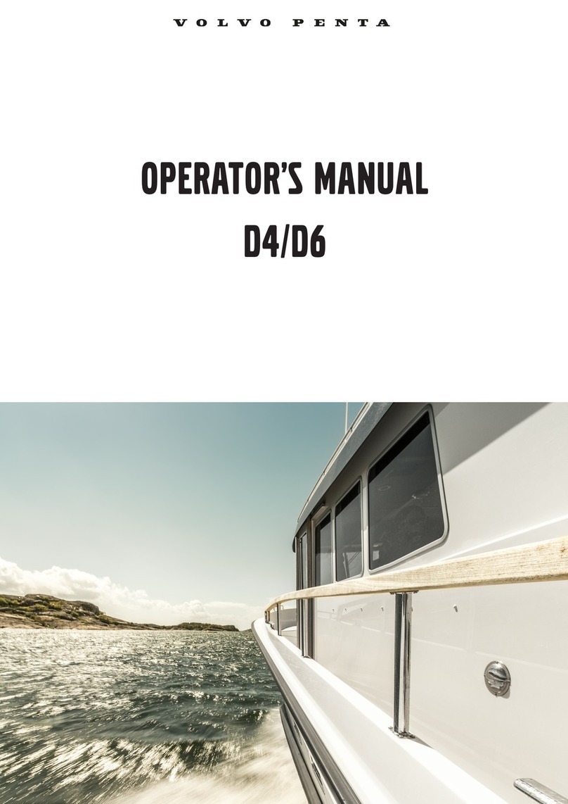
Volvo Penta D4 User manual

OPOP
ERER
AA
TT
OR’S MAOR’S MA
NN
UU
ALAL
D4, D6D4, D6
CALIFORNIACALIFORNIA
Proposition 65 WarningProposition 65 Warning
This operator‘s manual is available inThis operator‘s manual is available in
English.English.
Compelte the form t the end Compelte the form t the end
of the operator‘sof the operator‘s
manual to order a copy.manual to order a copy.
Diese Betriebsanleitung ist auch aufDiese Betriebsanleitung ist auch auf
Deutsch erhältlich.Deutsch erhältlich.
Ein Bestellcoupon ist am Ende der Ein Bestellcoupon ist am Ende der
Betriebs-Betriebs-
anleitung zu finden.anleitung zu finden.
Ce manuel d’instructions peut êtreCe manuel d’instructions peut être
commandé en français.commandé en français.
VV
ous trouverez un bon de commande à ous trouverez un bon de commande à
la finla fin
du manuel d’instructions.du manuel d’instructions.
Este libro de instrucciones puede soli-Este libro de instrucciones puede soli-
citarse en español.citarse en español.
El cupón de pedido se encuentra al final delEl cupón de pedido se encuentra al final del
libro.libro.
Den här instruktionsboken kan bestäl-Den här instruktionsboken kan bestäl-
las på svenska.las på svenska.
Beställningskupong finns i slutet av instrukti-Beställningskupong finns i slutet av instrukti-
onsboken.onsboken.
Questo manuale d’istruzioni può esse-Questo manuale d’istruzioni può esse-
re ordinato in lingua italiana.re ordinato in lingua italiana.
Il tagliando per l’ordinazione è riportato allaIl tagliando per l’ordinazione è riportato alla
fine del manuale.fine del manuale.
Dit instructieboek kan worden besteldDit instructieboek kan worden besteld
in het Nederlands.in het Nederlands.
De bestelcoupon vindt u achter in het instruc-De bestelcoupon vindt u achter in het instruc-
tieboek.tieboek.
Denne instruktionsbog kan bestillesDenne instruktionsbog kan bestilles
på dansk.på dansk.
Bestillingskupon findes i slutningen af instruk-Bestillingskupon findes i slutningen af instruk-
tionsbogen.tionsbogen.
Tämän ohjekirjan voi tilata myös suo-Tämän ohjekirjan voi tilata myös suo-
menkielisenä.menkielisenä.
Tilauskuponki on ohjekirjan lopussa.Tilauskuponki on ohjekirjan lopussa.
Este manual de instruções pode serEste manual de instruções pode ser
encomendado em português.encomendado em português.
O talão de requerimento encontra-se no O talão de requerimento encontra-se no
fimfim
do manual.do manual.
Áõôü ôï åã÷åéñßäéï ÷ñÞóçòÁõôü ôï åã÷åéñßäéï ÷ñÞóçò
äéáôßèåôáé óôçí áããëéêÞ ãëþóóá.äéáôßèåôáé óôçí áããëéêÞ ãëþóóá.
Ãéá íá ðáñáããåßëåôå Ýíá áíôßôõðï,Ãéá íá ðáñáããåßëåôå Ýíá áíôßôõðï,
óõìðëçñþóôå ôç öüñìá ðïõ âñßóêåôáé óôïóõìðëçñþóôå ôç öüñìá ðïõ âñßóêåôáé óôï
ôÝëïò áõôïý ôïõ åã÷åéñéäßïõ ÷ñÞóçò.ôÝëïò áõôïý ôïõ åã÷åéñéäßïõ ÷ñÞóçò.
This operator’s manual is available inThis operator’s manual is available in
Turkish/Russian.Turkish/Russian.
Complete the form at the end Complete the form at the end
of the operator’sof the operator’s
manual to order a copy.manual to order a copy.
Bu kullanýcý el kitabý Türkçe diller-Bu kullanýcý el kitabý Türkçe diller-
inde mevcuttur.inde mevcuttur.
Birnüshasýný sipariþ etmek için kullanýcý elBirnüshasýný sipariþ etmek için kullanýcý el
kitabýnýn sonundaki formu doldurun.kitabýnýn sonundaki formu doldurun.
Welcome aboardWelcome aboard
VV
olvo Penta marine engines are used olvo Penta marine engines are used
all over the world. They are used in all possible operatingall over the world. They are used in all possible operating
conditions for professional as well as leisure conditions for professional as well as leisure
purposes. purposes.
That’s not surprising.That’s not surprising.
After 100 years as After 100 years as
an engine manufacturer the Van engine manufacturer the V
olvo Penta name has become a symbol olvo Penta name has become a symbol
of reli-of reli-
abilityability
, technical innovation, top , technical innovation, top
of the of the
range performance and range performance and
long service long service
life. life.
We also believeWe also believe
that this that this
is what you is what you
demand and demand and
expect of your Vexpect of your V
olvo Penta engine.olvo Penta engine.
We would like you to read this We would like you to read this
operator’s manual thoroughly and consider the advice operator’s manual thoroughly and consider the advice
we give onwe give on
operation and maintenance before your maiden operation and maintenance before your maiden
voyvoy
age so that age so that
you will be ensured of you will be ensured of
fulfillingfulfilling
your expectations. your expectations.
Please pay attention to the Please pay attention to the
safety instructions contained in the safety instructions contained in the
manual.manual.
As owner of a VolvAs owner of a Volv
o Penta marine engine, we would also o Penta marine engine, we would also
like to welcome you to a like to welcome you to a
worldwideworldwide
network of dealers and service workshops to assist you with technical advice, service require-network of dealers and service workshops to assist you with technical advice, service require-
ments and ments and
replacement parreplacement par
ts. Please contact your nearest ts. Please contact your nearest
authorized Vauthorized V
olvo Penta dealer forolvo Penta dealer for
assistance.assistance.
We also invite you to visit our We also invite you to visit our
home page on home page on
the Internet the Internet
at www.vat www.v
olvopenta.comolvopenta.com
With warm regardsWith warm regards
AB VOLVAB VOLV
O O
PENPEN
TT
AA
Safety
Informatio
n
 ............................................ 3–7
General
...................................................................
3
Boat
travel...............................................................
4
Maintenance and
service .......................................
6
Introduction
...................................................
8–12
Running-in
.............................................................
8
Fuel and oil types
..................................................
8
Certificated engines
...............................................
9
Warranty inf
ormation .............................................
9
Identification numbers
..........................................
12
Presentation
...................................................
13–20
T
echnical Description............................................
13
Engine
monitoring and
EVC ................................
14
Orientation
...........................................................
17
Instrumentation
 ..............................................21-44
Ignition lock
...........................................................
21
Start/stop panel
....................................................
21
Instruments
...........................................................
22
Alarm display
........................................................
23
EVC
control
panel.................................................
26
EVC system tachometer
.......................................
27
EVC system
display
..............................................
37
Controls
.......................................................... 45-47
Starting the engine
........................................48-50
Before starting
......................................................
48
General about starting
..........................................
48
Starting method
....................................................
50
Operation
 .........................................................51-57
Reading
instruments ...........................................
51
Acknowleging
alarms and
messages
.................
51
Cruising
speed
.....................................................
52
Synchronising
engine
speed
..............................
52
Changing helm
station ........................................
53
Operation ............................................................ 54
Pow
er trim ...........................................................
54
Pow
er trim Assistant
............................................
58
V
olvo
Penta
Lowspeed
.......................................
59
Running aground
..................................................
60
Stopping the engine
...................................... 61-62
Stopping
..............................................................
61
Laying
up .............................................................
61
Cold w
eather precautions ....................................
62
Maintenance schedule
 ...................................63-65
Maintenance
...................................................
66–96
Engine,
general
....................................................
66
Lubrication sy
stem
...............................................
70
Freshwater
system
...............................................
73
Seawater system
..................................................
76
Fuel
system
.........................................................
80
Electrical s
ystem
..................................................
83
Reverse gear
........................................................
88
Drive
.....................................................................
90
Steering
................................................................
93
Propellers
.............................................................
96
Laying up/Launching
 .....................................97-99
Inhibiting
...............................................................
97
Bringing out of winter storage
...............................
98
Painting the drive and underw
ater hull .................
99
In case of emergency
..................................
100-106
Starting using auxiliary batteries
........................
100
Emergency shifting
.............................................
101
Emergency
trimming
..........................................
102
Engine stop after
crash-stop
...............................
102
Fault-tracing
........................................................
103
Diagnostic function
.............................................
104
Malfunction message engine and
EVC-system
..
105
Faults
list ............................................................
106
Erasing
faults .....................................................
106
Fault register
 ...............................................107-113
Technical Data
 ............................................114-116
Engine
................................................................
114
Fuel
specification ...............................................
115
Drive
..................................................................
116
Reverse gear
......................................................
116
Pow
er
T
rim ..........................................................
116
Steering
..............................................................
116
Contents
Safety Information
Read this
chapter carefully
. It concerns
your safety
. This section describes how safety information
is presented in
the operator’s manual and on the
engine. It also gives a general account of
basic safety precautions to be
taken
when operating the boat and maintaining the engine.
Check that you have the
correct operator’
s manual before you read on. If this
is not the
case please con-
tact your Volvo Penta dealer.
If operations are performed incorrectly it could result in personal injury, or damage to property
or the engine. Read the operator’s manual carefully before operating or
servicing the
engine. If
anything is unclear
please contact your Volv
o Penta dealer for
assistance.
This symbol is used in
the book and
on the engine to
make you aware of safety information.
Always read these safety precautions
very carefully.
In the operator’s manual warning texts have the following priority:
WARNING!
If these instructions are not followed there is a danger of personal injury, exten-
sive damage to the product or serious mechanical malfunction.
IMPORTANT!
Used to draw your attention to something that can cause damage, product
malfunction or damage to
property.
NOTE!
Used to draw your attention to important information that will facilitate work or opera-
tions.
This symbol is used in certain cases on our products and refers to important information in
the operator’s manual. Ensure that warning and information symbols on the engine and trans-
mission are always visible and legible. Replace symbols that have been damaged or
painted
over.
Safety precautions to be taken when operating the boat
Your new boat
Read operator’s manuals and other information
supplied with your new boat. Learn to operate the
engine, controls and other equipment safely and cor-
rectly.
If this is your first boat, or is a boat type with which
you are not familiar, we recommend that you prac-
tice controlling the boat in peace and quiet. Learn
how the boat behaves at different speeds, weather
conditions and loads before casting
off for your “real”
maiden voyage.
Remember that the person driving a boat is legally
required to know and follow the current rules regard-
ing traffic and safety at
sea. Make sure you know the
rules that apply to you and the waters you are sailing
in by contacting the relevant authorities or organiza-
tion.
A good piece of advice is to take a course in sea-
manship.
We recommend that
you contact your
local
boating organization to find a suitable course.
Accidents
Statistics show that poor maintenance of boats and
engines and a lack of safety equipment are often the
cause of accidents at sea.
Ensure that your boat is maintained in accordance
with the relevant Instruction Manual and that the nec-
essary safety equipment is on-board and is service-
able.
Daily checklist
Make a habit of checking the engine and engine
compartment visually before operating the boat (
be-
fore the engine is started
) and after operating the
boat (
after the engine has been stopped
). This will
help you to quickly detect fuel, coolant or oil leaks
and spot anything else unusual that has or is about to
happen.
Maneuvering
Avoi
d violent and
unexpected changes in course and
gear engagement. This could cause someone on the
boat to lose their balance and fall over or overboard.
A rotating propeller
can cause serious
injury
. Check
that nobody is in the water before engaging ahead or
astern. Nev
er drive near
bathers or in
areas where
people could be in
the water.
Avoid trimming an outboard drive too much, as steer-
ing will be severely reduced.
Refueling
When refueling there is always a danger of fire and
explosion.
Smoking is forbidden and the
engine must
be switched off.
Never ov
erfill the tank. Close the fuel
tank filler cap
properly.
Only use the fuel recommended in the operator’s
manual.
The wrong grade of
fuel can cause operat-
ing problems or cause
the engine to stop. On a diesel
engine poor quality fuel can cause the control rod to
seize and the engine to overrev with a resultant risk
of damage to the engine and personal injury.
Do not
start the
engine
Do not start or run the engine with a suspected fuel
or LPG leak in the boat, nor when you are close to or
in a discharge of
explosive media, etc.
There is risk
for fire and/or
explosion in explosive surroundings.
Safety breaker
We recommend that you install and use a safety
breaker (accessory), especially if
you boat can travel
at high speeds. The safety breaker stops the engine if
the driver falls down and loses
control over the boat.
Safety Information
Carbon monoxide poisoning
When a boat is moving forward, it will cause a cer-
tain vacuum to form behind the boat. In unfortunate
circumstances, the suction from this vacuum can be
so great that the exhaust gases from the boat are
drawn into the cockpit or cabin and cause carbon mo-
noxide poisoning.
This problem is most prevalent on high, wide boats
with abrupt ster
n. In certain conditions, however
, this
suction can be a
problem on other boats, e.g. when
running with the
cover up.
Other factors that can in-
crease the effect of the suction are wind conditions,
load distribution, swells, trim, open hatches and port-
holes, etc.
Most modern boats,
howev
er, are designed in such
a way that this problem is
very rare. If suction should
arise anyway
, do not
open hatches or
portholes at
the fore of the
boat. Surprisingly
, this will otherwise
increase the suction. T
ry changing
speed, trim or
load
distribution instead. T
ry
taking down/opening or
in any
other way changing the setup
of the cover as well.
Get in touch with your boat dealer for help in obtain-
ing the best solution for your boat.
Checklist
●
Safety equipment Li
fe jack
ets for all
passengers, communication
equipment, emergency rockets
,
approved fire extinguisher
, first-aid equipment,
life belt, anchor, paddle, torch etc.
●
Replacement parts and tools:
impeller, fuel
filters, fuses, tape
, hose clamps, engine
oil, propeller
and tools for any repairs that might have to be carried out.
●
Get out your charts and go o
ver the planned route
.
Calculate distance and fuel
consumption.
Lis-
ten to the weather reports
●
Make sure that relations
or contact persons are inf
ormed when planning a longer v
oyage.
Re-
member to inform them if your plans have changed or been delayed.
●
T
ell your passengers and crew where the saf
ety equipment is stored and how to operate it.
Make
sure you are not the only person on board who knows how to start the boat and operate it safely.
This list can be added to because safety equipment and other requirements vary depending on the
type of boat
and how it is
used.
We recommend that you contact your local
boating organization for
more detailed information on safety afloat.
Safety Information
Safety precautions for maintenance and service operations
Preparations
Knowledge
The operator’s manual contains instructions on
how
to carry out general maintenance and service opera-
tions safely and corr
ectly
. Read the instructions
care-
fully before starting work.
Service literature covering more complicated opera-
tions is available from your Volvo Penta dealer.
Never carry out any work on the engine if you are
unsure of how it
should be done, contact
your V
olvo
Penta dealer who will be glad
to offer assistance.
Stop the engine
Stop the engine before opening or removing engine
hatches. Unless otherwise specified all maintenance
and service must be carried out with the engine
stopped.
T
o prevent accidental start
of the boat
engine remove
the ignition key
, turn
off the power supply to
the en-
gine at the main switches and lock them in the OFF
position before starting work. Put up a warning sign
in the control position that work on the engine is be-
ing carried out.
Approaching or working on an engine that is run-
ning is a safety r
isk. Loose clothing, hair, fingers or
a dropped tool can be caught in the rotating parts of
the engine
and cause
serious personal
injury
. V
olvo
Penta recommend that all servicing with the engine
running be
undertaken by
an authorized Volv
o Penta
workshop.
Lifting the engine
When lifting the engine use the lifting eyes installed
on the
engine (reverse gear where
installed). Alwa
ys
check that lifting equipment is in good condition and
has sufficient load capacity to lift the engine (engine
weight including reverse gear and any extra equip-
ment installed). For safety’s sake lift the engine
us-
ing an adjustable lifting beam. All chains and
cables
should run parallel to each other and as perpendicu-
lar as possible in relation to the top of the engine.
Bear in mind that extra equipment installed on the
engine may alter
its center
of gravity
. Special lifting
equipment may then be required in order to maintain
the correct balance and make the engine safe to han-
dle. Never carry out work on an engine suspended on
a hoist.
Before starting the engine
Reinstall all protective parts removed during service
operations before starting the
engine. Chec
k that no
tools or other items have been left on the engine.
Never start a turbocharged engine without installing
the air cleaner
(ACL).
The rotating compressor
in the
T
urbocharger unit
can cause
serious personal
injury
.
Foreign objects can also be sucked in and cause me-
chanical damage to the unit.
Fire and explos
ion
Fuel and lubrication oil
All fuel, most lubricants and many chemicals are
inflammable.
Read and follow the instructions on
the
packaging.
When carrying out work on the fuel system make
sure the engine is cold. A fuel spill onto a hot surface
or electrical components can cause a fire.
Store fuel soaked rags and other flammable material
so that there is no danger of them catching fire. Fuel-
soaked rags can self-ignite under certain conditions.
Do not smoke when filling fuel, oil or in proximity of a
filling station or in the engine room.
Non-original components
Components used in the fuel and ignition system
(gasoline engines) and
electrical systems on Volvo
Penta products are designed and constructed to
minimize the risk of fire and explosion.
Using non-original V
olvo Penta parts can result
in fire
or explosion on board.
Batteries
The batteries contain
and give off oxyhydrogen gas,
especially during charging. This gas is easily ignited
and highly volatile.
Do not under any circumstances smoke or use naked
flame or allow sparks in the vicinity of the batteries or
battery compartment.
Incorrectly connection a battery terminal cable or
jump-start cable can cause a spark which in its turn
can be sufficient to cause an explosion.
Start spray
Never use start spray or similar agents to start an en-
gine equipped with air pre-heating (glow plugs/starter
element).
This may cause an explosion in
the inlet
manifold. Danger of personal
injury
.
Safety Information
Hot surfaces and
fluids
There is always a risk of burns when working with
a hot engine. Beware of hot surfaces. For example:
the exhaust pipe, T
urbo unit, oil
pan, charge air
pipe,
starter element, hot coolant and hot oil in oil lines and
hoses.
Carbon monoxide poisoning
Only start the engine in a well-ventilated area. If op-
erating the engine in an enclosed space, ensure that
there is proper ventilation in order to remove exhaust
gases and crankcase ventilation emissions from the
working area.
Chemicals
Most chemicals such as anti-freeze, rustproofing
agent, inhibiting oil, degreasing agent etc. are haz-
ardous to health. Read and follow the instructions
on
the packaging.
Some chemicals such as inhibiting oil are inflam-
mable and dangerous if
breathed in as
well. Ensure
good ventilation and use a protective mask when
spraying.
Read and follow the instructions
on the
packaging.
Store chemicals and other hazardous materials out
of the
reach of
children.
T
o protect
the environment
please dispose of used or leftover chemicals at a
properly designated disposal site for destruction.
Cooling system
There is a risk of flooding when working on the sea-
water system.
T
urn off
the engine and
close the sea
cock (where installed) before starting work on the
system.
Avoid opening the coolant filler cap when the engine
is hot. Steam or hot coolant can spray out and cause
burns.
If work must be carried out with the engine at operat-
ing temperature and the coolant filler cap or a cock
open or a coolant hose disconnected, open the cool-
ant filler cap carefully and slowly to release pressure
before removing the
cap completely
. Note that the
coolant may still be hot and can cause burns.
Lubrication syste
m
Hot oil can cause
burns. A
void skin contact with hot
oil. Ensure that the lubrication system is not under
pressure before commencing work on
it. Nev
er star
t
or operate the engine with the oil filler cap removed,
oil can spray out.
Fuel system
Always use protective gloves when
tracing leaks.
Liquids ejected under pressure can penetrate body
tissue and cause ser
ious injury.
There is a
danger of
blood poisoning.
Always cov
er the generator
if it is located
under the
fuel filter.
The generator can be
damaged by spilled
fuel.
Electrical system
Cutting off power
Always stop the engine and break the current using
the main switches before working on the electrical
system. Isolate shore current to the
engine block
heater, battery charger, or accessories mounted on
the engine.
Batteries
The batteries contain an extremely corrosive elec-
trolyte. Protect your skin and clothes when charging
or handling
batteries. Alwa
ys use protective
goggles
and gloves.
If battery electrolyte comes into contact with unpro-
tected skin wash off immediately using plenty of wa-
ter and soap. If battery acid comes into contact with
the eyes, flush immediately with plenty of water and
obtain medical
assistance without
delay
.
Safety Information
The EVC system
The Electronic V
essel Control (EVC) system is
a so
called distributed system. The principle of a distrib-
uted system is to
have many small electonic units,
called nodes, located on suitable places in the boat.
The EVC nodes are the Powertrain Control Unit
(PCU) and the Helm
station Control Unit (HCU).
Nodes are located close to the components they
control. A helm node is located
close to the helm. A
powertrain node is mounted in the engine room.
Each node controls a number of adjacent compo-
nents, for example sensors, controls, instruments and
actuators.
Each PCU and HCU is programmed for a specific
engine individual. On the PCU and HCU there is a
sticker with chassis
no.
The chassis
no. shall corre-
spond to the sticker on the engine.
A data bus, a CAN bus, connects the nodes to each
other. Together they form a network and exchange
information and take advantage of
each others’ serv-
ices.
The principle of
forming a network of
nodes to
which all components are connected reduces wiring
radically.
CAN stands for Controller Area Network, an industry
standard for communication between nodes in distr
ib-
uted systems.
A distributed system supports a growing multiplicity
of system configurations
and optional
features. N
ew
nodes can be connnected to the network with mini-
mal wiring
redesign. New effectiv
e functionality can
be created by letting the nodes interact and combine
their capabilities, creating a more useful and safe
product.
Functionalities
Engine speed and gear shift
Speed and
gear shift contol
is handled electronically.
The reverse gear or stern drive has high speed shift-
ing protection. Dual function electronic controls works
in the EVC system as well as mechanical controls
with control adapters.
Engine
synchron
ization
Engine synchronization results in better comfort,
good fuel ecomomy and minimized wear due to less
vibration and reduced noise level. To enable syn-
chronization the master (port) and slave (starboard)
systems must be
able to communicate. Therefore a
synchronization cable has to be installed at the each
helm.
Instrumentation
The instruments use
a serial communication bus. The
serial communication bus in combination with EVC
radically reduces wiring and
simplifies installation.
EVC system tachometer
The EVC system tachometer is mandatory for boats
with EVC, unless the optional EVC system
display
is installed. The tachometer display shows operation
information, information massages and
alarms.
The
user selects what operation information to display
with the control
panel.
NOTE!
Only one operation in-
formation can be
displayed at one and the same
time.
The EVC system tachometer and control panel is
also used when calibrating
EVC functions.
Power Trim
The function is
considerably improved compared
to non EVC governed
Po
wer trim systems. EVC in-
troduces a new trim panel with the same design as
other EVC control panels. If you have a twin engine
installation the stern drives can be both individually
and simultaneously controlled.
Trimming in and out can be calibrated to suit the spe-
cific installation. T
o protect
the drive it
cannot be
tilted
when engine is running above a certain rpm.
The Power trim control panel shall be connected to
the
multilink bus
and the gauge
to the instrument
cable harness from
the HCU.
The cable harness for
stern drives has connectors for the power trim angle
sensor and the power trim pump.
Extra optional equipment
EVC system display
The EVC system display is a complement or replace-
ment for EVC system tachometer and optional in-
struments. The display shows operation information,
information massages and alar
ms.
The user selects
what operation information to display with the buttons
on the display. The EVC system display can display
more than one operation information at one and the
same time.
The display also has access
to the same
display mode and calibration functions as
for the EVC
system tachometer display.
Trim indicator
A trim indicator sender is included in all aquamatic
drives.
The trim angle
can be displayed on the EVC
system tachometer. It is also advised to install a
trim
instrument. The instrument shows trim angle and trim
range. If a trim instrument is used it must be connect-
ed to the
instrument serial
communication bus.
Fuel level
Fuel level can be displayed on the EVC system
ta-
chometer if a (3-180 ohm or 240-30 ohm) fuel level
sender is installed in the fuel tan
k.
The sender
is
connected to the
PCU–engine cable harness. If a
fuel level gauge is used it must be connected to the
instrument serial
communication bus.
Presentation
Fresh water level
Fresh water lev
el can be
displayed on the EVC sys-
tem tachometer if a (3-180 ohm) fuel level sender is
installed in the water tank. The sender is connected
to
the PCU–engine cable harness. If a fresh
water level
gauge is used it must be connected to the instrument
serial communication
bus.
Rudder indicator
Rudder angle can be displayed on the EVC system
tachometer if a (3-180 ohm) rudder indicator is in-
stalled to the dr
ive/rudder.
The sender is
connected to
the PCU–engine cable harness. If a rudder instrument
is used it must be connected to the instrument serial
communication bus.
Multisensor (Boat speed, depth and water temp)
Boart speed, depth and water temperature canbe dis-
played on the EVC system tachometer if a multi sen-
sor is installed on
the boat. The sensor is connected
to the multilink cable. If instruments (speed, depth,
water temp.) are used they must be connected to the
instrument serial
communication bus.
Power T
rim A
ssista
nt
The function power trim assistant adjust trim angle
automatically according to engine speed (rpm). EVC
supports power trim assistant if software for power-
trim assistance is installed (order and download from
VODIA website).
Boat speed
Boat speed can be shown on the EVC system ta-
chometer, if a multisensor or NMEA 0183/NMEA 2000
compatible component (plotter, GPS, paddle wheel
etc) is installed. If a speedometer is used it must be
connected to the instrument serial communication
bus. .
Trip computer
EVC supports trip computer functions if following are
installed.
-
Multisensor
or
NMEA
0183/NMEA
2000
compat-
ible component (plotter, GPS, paddle wheel etc)
-
Fuel
level
sender
-
Software
for
trip
computer
(order
and
download
from VODIA website).
T
rip computer information
can be displayed on the
EVC system tachometer or/and on the optional EVC
system display.
Presentation
Orientation
D4 with drive,
port
11.
Sea w
ater filter
12.
Sea water
pump
13.
Fuel
filter
14.
Oil
dipsti
ck
15.
Oil bypass
filter
16.
Oil filter
17.
Starter
D4 with drive,
starboard
1. Zinc
anode
2.
Cooling
water
intake
3. Zinc
anode
 4. Turbocharger
5.
Crankcase
ventilation
filter
6. Aux
Stop
7. Air
filter
 8. Compressor
9.
EDC
control
module
10.
Generator
11.
Oil filler
cap
1
2
3
4
5
6
7
8
9
11
10
11
12
13
14
15
16
17
18
19
Presentation
D4 with reverse gear, port
8.
Sea
water
pump
9. Fuel
filter
10.
Oil dipstick
(engine)
11.
Oil bypass
filter
12.
Oil filter
13.
Starter
14.
Charge a
ir cooler
D4 with reverse gear, starboard
 1. Turbocharger
2.
Crankcase
ventilation
filter
3. Aux
Stop
4. Air
filter
5.
EDC
control
module
 6. Generator
7.
Oil
filler
cap
8
9
10
11
12
13
14
15
16
1
2
3
4
5
6
7
Presentation
D6 with drive, starboard
1. Zinc
anode
2. Co
oling
water
intake
3. Zinc
anode
 4. Turbocharger
5.
Crankcase
ventilation
filter
6. Aux
Stop
7. Air
filter
 8. Compressor
9.
EDC
control
module
10.
Generato
r
11.
Oil filler
cap
D6 with drive, port
11.
Sea w
ater filter
12.
Sea water
pump
13.
Fuel
filter
14.
Oil dipstic
k
15.
Oil bypass
filter
16.
Oil filter
1
2
3
4
5
7
6
8
9
11
11
12
13
14
15
16
17
18
19
10
Presentation
D6 with reverse gear, starboard
 1. Turbocharger
2.
Crankcase
ventilation
filter
3. Air
filter
4. Aux
Stop
5.
EDC
control module
 6. Generator
7.
Oil
filler
cap
D6 with reverse gear, port
8.
Sea
water
pump
9. Fuel
filter
10.
Oil dipstick
(engine)
11.
Oil bypass
filter
12.
Oil filte
r
13.
Starter
14.
Charge
air cooler
8
9
10
11
12
1
3
1
4
1
5
16
1
2
3
4
5
6
7
Presentation
Battery (orange indication)
The battery lamp lights up if the alternator is not
charging. Stop the engine if this lamp lights up during
operation. If the lamp lights up, this can be due to a
fault in the electrical system or because the alternator
drive belt is
slack.
Check the alternator
drive belts. Please refer to
“Maintenance: Engine,
general”.
Also check that there is no poor contact/broken wires.
WARNING
!
Do not continue
operation if there
is
any problem with the alter
nator drive belts. This
could cause serious engine
damage.
Coolant temperature (red indication)
The coolant temperature lamp lights up when the
coolant temperature is too high. Stop the engine if this
lamp lights up dur
ing operation.
Check the coolant
level.
Please refer to “Maintenan-
ce: Fresh water system”.
Check that
the sea water
filter is not
blocked.
Please
refer to “Maintenance: Sea water system”
Also chec
k the
impeller in
the sea
water pump
.
Please refer to “Maintenance: Sea water
system”.
Please ref
er to the “In case
of emergency” chapter, and
you will find detailed information about recommended
action in th
e “Diagnostic function” section.
WARNING
!
Do not open
the coolant filler
cap
when the engine
is warm, except in emergencies.
Steam or hot
fluid could spray out.
Instruments
Coolant level (orange indication)
The coolant lamp lights up when the coolant level is
too low.
Check coolant lev
el.
Please refer to
“Maintenan-
ce: Fresh water system”.
Red warning indication, serious fault
If the red warning indication is shown during opera-
tion, a
serious fault
has occured.
Please refer to the “In case
of emergency” chapter,
and you will find detailed information about recom-
mended action in
the “Diagnostic function” section.
Orange alarm indication, fault
If the orange alarm indication is shown during opera-
tion, a
fault has
occured.
Please refer to the “In case
of emergency” chapter,
and you will find detailed information about recom-
mended action in
the “Diagnostic function” section.
Instruments
Navigation wheel
Used to navigate through the menus shown on the
tachometer EVC
system display
. Navigate through
the menus by turning the wheel. Depress the wheel to
confirm a selection.
T
achometer display selection (twin
installa-
tion, port or
starboard tachometer)
Is used to select which of the engines menu systems
should be navigable from the
control panel. The menu
is shown on the display of the corresponding engines
tachometer.
Select port
or starboard.
Indication
(red/green):
Off:
Not possible to
navigate in menu.
Lit:
Possib
le to navigate in
menu for selected engine,
port (red), starboard (green).
Multifunction button
Used to increase or decrease the instrument’s and
panel’s backlighting.
Depress the button for at least 1 second to turn the
backlighting on or off. The backlighting can be adjust-
ed in five stages by pressing the multifunction button.
If the button is pressed on a inactive control panel, op-
erating information is shown on the display(s) and it is
possible to navigate in the
menus.
Back button
Used to back a step in the menu.
IMPORTANT!
Always press the buttons firmly,
and for at least one second each time.
Activation button
Used to activate and lock the control panel and the
helm station.
Indication
(red):
Off:
Control panel not
activated.
Lit:
Control panel
activated.
Flashes:
Control panel not activated due to the con-
trol lever not being in neutral or the system has been
locked from another control
panel.
Padlock
The padlock symbol lights if the control panel is locked
manually
by
depressing
the
-button,
or
if
exchange
has been activated by routine ”Change of control
panel during jour
ney”.
Lit:
The system is loc
ked and the engine c
an only be
controlled from the activated control
panel.
Neutral button
Used to disengage the drive/reverse gear so that the
engine speed can be increased without driving (warm-
ing up mode).
Indication
(green):
Off:
Drive/rev
erse gear
engaged.
Lit:
Control lever in
neutral.
Flashes:
Drive/reverse gear disengaged or system
in
calibration
mode.
This button is also used for:
- Activation of the Volvo Penta Lowspeed/Trolling func-
tion (optional). F
or more
information please refer to
chapter
“Operation” section
“Volvo Penta Lowspeed/
Trolling”.
- Enabeling of emergency
trimming. For more
informa-
EVC control panel
The control panel
is used in combination
with the EVC system tachometer. The tachometer display shows oper-
ating information and menus that can be navigated from the control panel.
Instruments
Main menu structure
EVC
System T
achometer
Introduction
Volvo Penta EVC System Tachometer presents rele-
vant boat and engine information to the helmsman. In-
formation is presented on a display in the tachometer.
Information is depending on engine model, number of
sensors and type of
accessories.
Using the instrument
Start-up screen
This is the
start-up screen
for the EVC System T
a-
chometer.
After a few seconds the first
item in MAIN
MENU will appear.
Main menu
Navigating the menus
Navigate the menus by turning NAVIGATION WHEEL
clockwise or counter-clockwise. Vie
ws with
a POIN-
TING HAND-symbol indicates a SUB-MENU. To enter
a SUB-MENU, push NAVIGATION WHEEL.
Speed (Optional)
Boat speed. Requires multisensor or GPS.
Water temp (Optional)
Water temperature. Requires multisensor.
Depth (Optional)
Water depth. Requires
multisensor
.
Trip menu (Optional)
S
hows trip information. Requires the
following:
-
Multisensor
or
NMEA
0183/NMEA
2000
compatible
component (plotter, GPS, paddle wheel etc)
-
Fuel
level
sender
-
T
rip
computer
software
Gauges menu
Shows data parameters.
Settings menu
The SETTINGS MENU allows the user to set various
options for the EVC System and to calibrate various
parameters.
Faults list
Number after word FAULTS indicates number of faults
stored in FAULTS LIST. List is reset when system is
rebooted.
Trip menu
Gauges menu
Settings menu
Faults list
Instruments
Trip menu (extra optional)
In the TRIP MENU the user gets trip information from the EVC System and the user is allowed to select which
view that should
be presented
in the
EVC System T
achometers MAIN MENU
as trip
information.
T
o get
trip infor-
mation following are required:
-
Multisensor or
NMEA 0183/NME
A 2000
compatible c
omponent (plotter
, GPS
, paddle
wheel etc)
-
Fuel
level
sender
-
T
rip
computer
software
NOTE!
The accuracy of trip information concerning, and based on, remaining fuel volume depends on which
method the user has choosen for calibrating the fuel tank.
When in TRIP MENU, select view by turning NAVIGATION WHEEL. To select view as favorite, push NAVIGA-
TION WHEEL. Sys
tem retur
ns to MAIN
MENU.
Push BACK BUTT
ON to retur
n to MAIN MENU without
setting a new favorite.
Units are user selectable. See section "Units"
FUEL REMAINING:
Fuel remaining (l, Gal).
FUEL ECONOMY:
Instantaneous fuel rate per dis-
tance (l/nm, l/km, l/mile, Gal/nm, Gal/km, Gal/mile).
FUEL RATE:
Instantaneous fuel rate per hour (l/h,
Gal/h).
DISTANCE TO EMPTY:
Distance to empty based on
instantaneous fuel rate, remaining fuel and speed
(nm, km, miles).
TIME TO EMPTY:
Time to empty based on instanta-
neous fuel rate and remaining fuel (h).
TRIP DISTANCE:
T
rip distance
since last reset
(nm,
km, miles).
TRIP FUEL:
T
rip fuel used
since last reset (l,
Gal).
TRIP FUEL ECONOMY:
Average fuel rate per dis-
tance since last reset (l/nm, l/km, l/mile, Gal/nm, Gal/
km, Gal/mile).
TRIP FUEL RATE:
Average fuel rate per hour since
last reset (l/h, Gal/h).
TRIP TIME:
T
rip engine hours
since last reset (h).
Trip menu structure
Instruments

Other manuals for D4

6

This manual suits for next models

1

Other Volvo Penta Boat manuals

Volvo Penta 22 Series User manual

Volvo Penta

Volvo Penta 22 Series User manual

Volvo Penta D6 User manual

Volvo Penta

Volvo Penta D6 User manual

Volvo Penta D1 Series User manual

Volvo Penta

Volvo Penta D1 Series User manual

Popular Boat manuals by other brands

Skeeter 200-SX owner's manual

Skeeter

Skeeter 200-SX owner's manual

Yamaha Waverunner VXS VX1800 Service manual

Yamaha

Yamaha Waverunner VXS VX1800 Service manual

Pakboats Puffin II Assembly and User Information

Pakboats

Pakboats Puffin II Assembly and User Information

Four winns V Series owner's manual

Four winns

Four winns V Series owner's manual

Thaijetboard Jetboard 2011 user manual

Thaijetboard

Thaijetboard Jetboard 2011 user manual

YAMARIN Cross 57 Bow Rider owner's manual

YAMARIN

YAMARIN Cross 57 Bow Rider owner's manual

Bayliner 197 owner's manual

Bayliner

Bayliner 197 owner's manual

Hunter Legend 37 owner's manual

Hunter

Hunter Legend 37 owner's manual

Four winns 338 Vista owner's manual

Four winns

Four winns 338 Vista owner's manual

Dufour 430 owner's manual

Dufour

Dufour 430 owner's manual

Pakayak Bluefin 14 quick start

Pakayak

Pakayak Bluefin 14 quick start

Gumotex K2 user manual

Gumotex

Gumotex K2 user manual

Jeanneau sun odyssey 33I owner's manual

Jeanneau

Jeanneau sun odyssey 33I owner's manual

Gumotex SEAWAVE user manual

Gumotex

Gumotex SEAWAVE user manual

Sea Ray 250 Select EX Specific information manual

Sea Ray

Sea Ray 250 Select EX Specific information manual

Williams Turbojet J/T 285 Owner's handbook

Williams

Williams Turbojet J/T 285 Owner's handbook

Maxum 2400 SC3 Owner's manual supplement

Maxum

Maxum 2400 SC3 Owner's manual supplement

KAYAKS2FISH NEXTGEN10 owner's manual

KAYAKS2FISH

KAYAKS2FISH NEXTGEN10 owner's manual

manuals.online logo
manuals.online logoBrands
  • About & Mission
  • Contact us
  • Privacy Policy
  • Terms and Conditions

Copyright 2025 Manuals.Online. All Rights Reserved.