Von Duprin HH KAW 9847 User manual
*24203424*
24203424
Devices covered by these instructions:
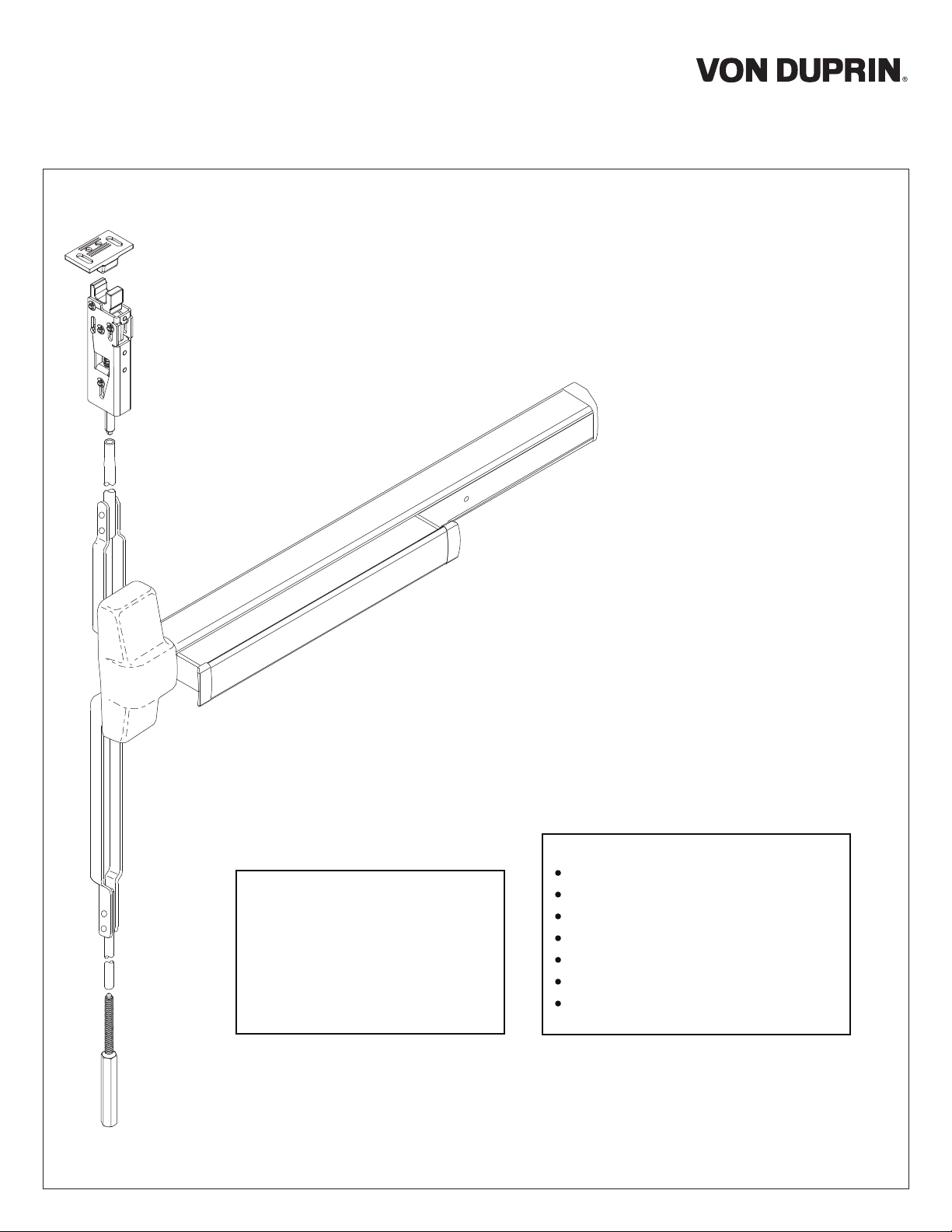
HH 98/9947 Concealed Vertical Rod Exit Device
HH CD98/9947 (Cylinder Dogging) Concealed Vertical Rod Exit Device
HH EL98/9948 (Electric Latch Retraction) Concealed Vertical Rod Exit Device
Special tools needed:
5/64” hex wrench
#10-24 tap
Drill bits: #25, 1/8”, 1/4”,
5/16”, 13/32”
Index:
Screw chart ............................. 2
Door preparation chart............ 3
Device installation ................ 4-5
Optional equipment ............. 7-8
Cut device.............................. 8
Please give these instructions to building owner after device is installed
Frame preparation .................. 5
Adjust rods .............................. 6
Concealed Vertical Rod Exit Device for Metal Door Applications
HH (KAW) 98/9947
Installation Instructions

2
SCREW CHART
#10-24 x 1”
#10-24 x 1-1/2”
Surface mount or
Sexbolts (2-1/4” door)
Sexbolts (1-3/4” door)
#10-24 x 3/4”
#10-24 x 1-1/8”
A
B
C
E
F
G
H
D
#8-18 x 3/8” Thread cutting
Surface mount or
Sex bolts (2-1/4” door)
#10-16 X 3/8” Thread cutting
Centercasecover
Sexbolts (1-3/4” door)
Endcap
-Packagedwithtrim -
#10-24 x 1-3/8”
#10-24 x 1-7/8”
990 trims (1-3/4” door)
990 trims (2-1/4” door)
Latch screw
HH guide
#10-32 X 3/8”
#12-24 X 1/2”HH strike
#8-32 X 5/16” Retaining clip
Retainingclip
Rod adjusting screw
3
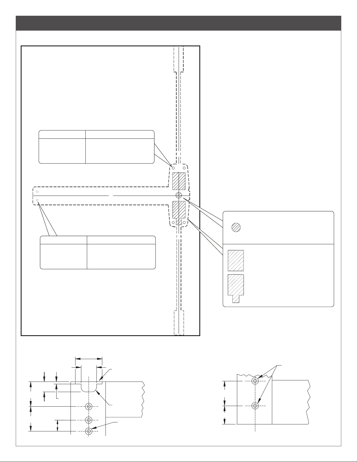
DOOR PREPARATION CHART
Go to instructions on next page before using preparation chart
X
X
C
L
*End cap bracket - 2 holes
*Prepare holes after lock side of device
is mounted and hinge side is equal
distance to bottom of door
Center case - 4 holes
Surface mount Sex bolts or 990 trims
#25 Drill
#10-24 tap
1/4” Drill (device side)
13/32” Drill (trim side)
Door Cut-outs
TopPreparation Bottom Preparation
For HH 98/9947
Trace cut-outs from
plastic template
(cut device side only)
Outside cylinder applications:
Mark with template and cut-out:
Metal door (cut device side)
Wood door(cut thru)
Surface mount Sex bolts or 990 trims
#25 Drill
#10-24 tap
1/4” Drill (device side)
13/32” Drill (trim side)
C
L
9/16"
3/4"
1-1/32"
2-3/8"
1-1/2"
1/8"
1" Cutout on inside
face only
1/4" radius
#9 (0.196") drill, c'sink 82°
to 13/32" dia., 5 holes,
inside face only
1-3/8"
7/8"
C
L
Rod type latch
location
C
L

4
1 Draw Horizontal Device Center Line (C
L)
C
L
RHR shown
(LHR opposite)
39-5/8”
to bottom of
door
2 Determine Correct Backset, then Mark 4 Holes for
Device Center Case Using Template
98/9947
(non-fire rated device)
single or double door
C
L
Mark 4
holes
2-3/16”
backset
C
L
3 Prepare Door per Preparation Chart on Page 3
See trim instructions
for pull side door
preparation. Line X-X
in trim instructions is
same as device C.
L
4 If Using an Outside Cylinder, Check NL Drive Screw
and Install Tailpiece Guide
With NL drive screw removed, key locks and unlocks lever, knob,
or thumb piece. For trims listed below,
REMOVE NL drive screw.
996L 696TP 990TP
996K 697TP
With NL drive screw installed, key retracts latch bolt.
DO NOT remove
NL drive screw for the following applications:
NL, EO, DT trims and 98/99-2 double cylinder devices (i.e. TP-2,
L-2, and K-2).
If trim being installed is "BE" (i.e. 996L-BE), trim lock tumbler on
back of device must be in
UP position before device is installed.
This allows trim to be unlocked at all times.
*
*996L-BE
*996K-BE
*E996L
*E996L-BE
*696TP-BE
*697TP-BE
*990TP-BE
NL drive screw
Factory installed on
back of center case
Correct
Orientation
(RHR shown)
Incorrect
Orientation
trim lock
tumbler in
UP position
If necessary,
remove drive
screw and
rotate cam
until trim lock
tumbler is in
UP position,
then reinstall
drive screw
360˚
5 Assemble Rods and Latches and Adjust Length for
Proper Door Height
Top
length
Bottom
length
Fine tune the
overall length
by threading
latch in or out
of rod
Follow red and blue instruction cards with
rods to set initial rod length

5
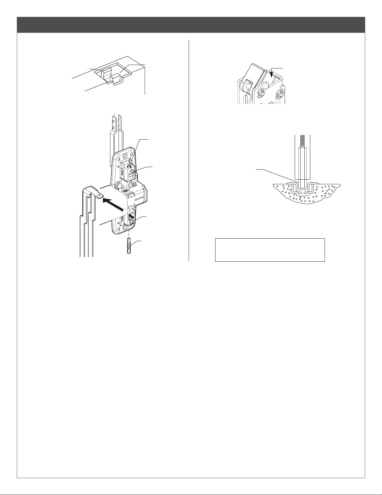
6 Install Rods and Latches as Shown
D
G
F
Bottom rod
& bolt
Top rod
& latch
Top rod
Bottom
rod
Device aligns with
mounting holes
which were
prepared in step 3.
7 Secure Device to Door as Shown, then Hang Door on
Frame
B
C
A
See “Screw Chart”
on page 2 for screw
types and sizes
Center
case
2” Minimum clearance
(with end cap removed)
If device is too long for
door, see “Cut Device”
on back cover
Mounting
bracket flush
Trim
(optional)
Device equal
height to bottom of
door on each end
Mark and prepare
2 mounting holes
and secure screws
(see page 3)
8 Prepare and Install Top Strike
3/4"3/4"
3/4"
of top latch
2x #16drill
tap 12-24
Blade
stop
is set
2x #16 drill & tap 12-24
use strike astemplate
once finalstrike location
9 Install bottom strike or prepare threshold.
1/8" 5/8"
STRIKE
C
1/4"
1"
2 3/4"
L
29/32"
385-A bottom strike
Threshold application
Flat threshold
application
Remove material as
necessary to accommodate
5/8” latch bolt throw
Stop
Latch case C
L
3/4"
10 Adjust Rods and Install Center Case Cover
J
Center case
cover
Remove protective
film from pushbar
See “Adjust Rods” on page 6 for
adjustment procedure
6
ADJUST RODS
Install bottom adjusting screw through bottom
rod (Figure 2).
With top latch bolt still retracted, adjust bottom bolt
so that bolt clears floor and bottom strike.
Turn bottom locking screw in. Do not over-tighten.
Open door and verify top latch bolt
is fully extended (Figure 1).
Loosen bottom locking
screw (Figure 2).
Disconnect bottom
vertical rod by removing
bottom adjusting screw.
Loosen top locking screw.
Rotate top adjusting screw
clockwise until top latch
bolt drops
(Figure 3).
Turn top
locking screw
in. Do not
over-tighten
Release pushbar.
Depress pushbar and ensure
latchbolt falls.
1.
2.
3.
4.
Depress pushbar and dog
device
5.
6.
7.
8.
9.
10.
11.
12.
Check device operation by opening and closing door
several times from the inside.
Redo adjustment procedure if :
- Top latchbolt does not retract
- Bottom bolt does not clear
floor and bottom strike
13.
Bottom
latch bolt
(clears floor
and strike)
Figure 2
Bottom
adjusting
screw
Top
locking
screw
Top
adjusting
screw
Bottom
locking
screw
Figure 3
Figure 4
Top latch bolt Shown fully
extended
Figure 1
Latch bolt retracted
(flush with latch case)

7
OPTIONAL EQUIPMENT
1. Remove mortise cylinder cam and reinstall in reverse (Figure 6).
2. Insert key and rotate cam to install the cylinder to the cover plate (Figure 7).
3. Remove key to slide cover plate in position in the mechanism case.
Std. mortise
cylinder
Mortise
cylinder
cam
Std. mortise
cylinder
Mortise
cylinder
cam
CD function conversion
Figure 6
Figure 7
Std. mortise
cylinder
Cylinder
collar
Dogging
plate cover
Offset toward
pushbar
Cylinder
locating washer
Cylinder
lock nut
Mechanism
case
Turn cylinder key clockwise approx. 1/8
turn for standard dogging
Dogging procedure
Depress pushbar
CD (CYLINDER DOGGING)

© Allegion 2018
Printed in U.S.A.
24203424 Rev. 02/18-c
CUT DEVICE
1 Measure amount to cut o device.
2” Minimum clearance
(with endcap removed)
dengilaeciveD
gnitnuomhtiw
seloh
”61/5
Note
If 5/8” diameter wire access hole
has been predrilled in door, cut
device 5/16” from center of hole.
2 Tape and mark area being cut.
Tape
Cover plate
(flush to pushbar)
Pushbar
Remove anti-rattle clip
3 Cut device square.
Cut device square
and remove all
burrs
NOTE: Device must
be cut squarefor
proper end cap fit
4 Slide anti-rattle clip into device.
elttar-itnA
edisnipilc
”2
.nim
Customer Service
1-877-671-7011 www.allegion.com/us
This manual suits for next models
1
Table of contents
Popular Garage Door Opener manuals by other brands

Craftsman
Craftsman 139.3050 quick start guide

Quirky
Quirky ASCEND installation instructions

Beam Labs
Beam Labs beamUP Series product manual

Overhead door
Overhead door legacy 650 Programming and operating manual

Linear
Linear LDCO801 Homeowner's instructions

Chamberlain
Chamberlain Power Drive Security+ HD200CD owner's manual


Craftsman
Craftsman 139.53662SRT2 owner's manual

Overhead door
Overhead door 555 Installation instructions and owner's manual

Chamberlain
Chamberlain Security+ 1215EM FS2 owner's manual

Multi-code
Multi-code 1090 installation instructions

Challenger
Challenger 9300M Installation and owner's manual

Roger
Roger AYRON Series INSTRUCTIONS AND RECOMMENDATIONS FOR THE INSTALLER