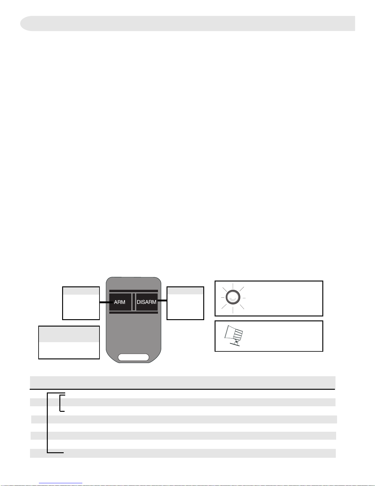
Voxx ELITE911 User manual

Vehicle Security System
INS0883
Rev. A
11/98
Installation Instructions
This device complies with part 15 of the FCC rules and with RSS-210 of the
industry Canada.Operation is subject to the following two conditions:(1) this
device may not cause harmful interference, and (2) this device must accept any
interference received, including interference that may cause undesired operation.
Technical Support
For Authorized Dealers - (800) 421-3209
Hours: 8:00 a.m. - 7:00 p.m. EST Monday thru Friday
10:00 a.m. - 2:00 p.m. EST Saturday
Avoid mounting components or
routing wires near hot surfaces
Avoid mounting components or
routing wires near moving parts
Tape or loom wires under hood for
protection and appearance
Use grommets when routing wires
through metal surfaces
Use a voltmeter for testing and
verifying circuits
PROFESSIONAL INSTALLATION
STRONGLY RECOMMENDED
Installation Precautions:
Roll down window to avoid locking
keys in vehicle during installation
Y10 / Y11

2
ORANGE/BLACK
VIOLET
WHITE RED
WHITE
TAN
RED
BLACK
BLUE/BLACK
GREEN/BLACK
STARTER KEY
STARTER MOTOR
TRUNK RELEASE (-) (Y-11 ONLY)
+12 VOLTS
CHASSIS GROUND
(-) LOCK / (+) UNLOCK
(-) UNLOCK / (+) LOCK
PARKING LIGHT OUTPUT (+)
RED
BLACK
ORANGE
SIREN OR
HORN
OUTPUT (-)
SHOCK SENSOR
WHITE
YELLOW
GREEN
GRAY
BLUE
BROWN
POSITIVE DOOR TRIGGER
NEGATIVE DOOR TRIGGER
NEGATIVE HOOD/TRUNK TRIGGER
DISARM
BUTTON
BROWN
SWITCHED
POWER
BLACK
RED
STATUS
INDICATOR
+12 VOLTS
FUSED +12V SOURCE
ILL. ENTRY / ARMED OUTPUT (-) (Y-11 ONLY)
System Layout
Refer to Wire Color / Location Chart for specific wire color,
location, and polarity information.
Module Identification:
7 Tab Connectors = Y-11
6 Tab Connectors = Y-10

3
+12V
Horn
Module ORANGE wire
1. Installation
A. Siren / Horn (ORANGE on 3-Pin Connector)
Make appropriate connections below.
Siren
• Mount bell housing downwards.
• Use at least two (2) screws to secure siren to mounting location.
• Connect siren BLACK wire to module ORANGE wire.
• Connect siren RED wire to a fused +12-volt source.
Horn
Circuit verification
-
Negative Systems
- Target wire will register ground when horn is pressed.
Positive Systems
- Target wire registers voltage when horn is pressed.
Diagram 1
Horn Wire Relay Diagram 1 Connect to target wire.
Positive Negative
Connection
B. 12V+ Main Feed (RED)
• Connect to vehicle battery or to main 12-volt lead at ignition switch harness.
Circuit Verification
- Target wire registers voltage at all times.
C. 12V+ Switched Feed (BLUE on 7-Pin Connector)
• Connect to switched 12-volt lead at ignition switch harness.
Circuit Verification
- Target wire registers voltage when ignition key is turned to the
ON position and START position.
D. Ground (BLACK)
• Attach to grounded metal point of vehicle chassis.
Note: When installing multiple components (such as an alarm and remote starter),
ground the units separately.
Fused

4
Diagram 2
DoorSystem -Relay Needed
G. Illuminated Entry (VIOLET on 3-Pin Connector) (Y-11 Only)
•
Circuit Verification -
Target wire is usually the door pin switch wire. Refer to
section F for verification guideline.
• Add a relay and connect as shown below:
H.Trunk / Hatch Release (TAN) (Y-11 Only)
•
Circuit Verification
- Refer to VehicleWire Color and Location Chart for circuit
type and location, or verify the vehicle wire using the following guideline:
•
Positive Systems
- Target wire registers voltage when the trunk / hatch is
opened using the vehicle button.
•
Negative Systems
- Target wire registers ground when the trunk / hatch is
opened using the vehicle button.
1. Installation
F.Door Pin Switches (YELLOW orWHITE on 7-Pin Connector)
Connect appropriate module wire to vehicle target wire. (See diagram 2 below.)
CircuitVerification
- Refer to VehicleWire Color and Location Chart for circuit
type and location, or verify the vehicle wire using the following guideline:
•
Positive Systems
- Target wire registers voltage when any door is opened.
•
Negative Systems
- Target wire registers ground when any door is opened.
E. Starter Interrupt
• WHITE/RED -Starter Key Side
• WHITE - Starter Motor Side
• Connect to vehicle starter wire at ignition switch harness.
Circuit Verification
- Target wire registers voltage only when ignition key is turned
to the START position.
Circuit Verification after starter wire is cut:
• KEY SIDE of starter wire registers voltage when ignition key is turned to
the START position.
• MOTOR SIDE of starter wire registers no voltage.
Trunk Release Wire Relay Diagram 3 Connect to target wire.
Positive Negative
Connection

5
Parking Light System - Relay Needed Diagram 4
K. Power Door Locks
• BLUE/BLACK: (-)Lock, (+)Unlock
• GREEN/BLACK: (-)Unlock, (+)Lock
•
CircuitVerification
- Refer to VehicleWire Color and Location Chart for circuit
type and location.
1. Installation
Diagram 3
I. Parking Lights (ORANGE/BLACKWire on 3-Pin Connector)
•
CircuitVerification
- Refer to VehicleWire Color and Location Chart for circuit
type and location, or verify the vehicle wire using the following guideline:
•
Positive Systems
- Target wire registers voltage when parking lights are on.
•
Negative Systems
- Target wire registers ground when parking lights are on.
Connections Positive System Negative System
Parking Lights Connect to Target wire • Add relay (dia. 4)
J. Hood /Trunk Pin Switch (GREENWire on 7-Pin Connector)
•
CircuitVerification
- Refer to VehicleWire Color and Location Chart for circuit
location, or install a pin switch and connect to the module GREEN wire.

6
BLUE/BLACK - LOCK(-)
GREEN/BLACK - UNLOCK(-)
Diagram 6
Type 2 - Positive 5-Wire Door Lock System
Type 3 - Negative 3-Wire Door Lock System
1. Installation
GREEN/BLACK - UNLOCK (-)
BLUE/BLACK - LOCK (-)
Diagram 7
Diagram 5
Type 1 - Positive 3-Wire Door Lock System
GREEN/BLACK - LOCK (+)
BLUE/BLACK - UNLOCK (+)
Type1 Type3Type2 Other
Dia. 5 Dia. 7
Dia. 6 See specifications in
Vehicle Wire Color /
Location Guide or call
TechnicalSupport
Type4
Dia. 8
Door Locks
Connections Type5
Dia. 9

7
Diagram 9
20A
BLUE/BLACK - LOCK(-)
GREEN/BLACK - UNLOCK(-)
ModuleWires
BLUE/BLACK - LOCK(-)
GREEN/BLACK - UNLOCK(-)
ModuleWires
1. Installation
Diagram 8
Type 4 - Vacuum Door Lock System
Note: Turning on option 8, the Long Locks feature, in program-
mable options is required with this type of locks.
L. Status Indicator (GRAYWire on 7-Pin Connector)
• Locate a visible location on the dash with 11/2” clearance.
• Drill 1/4” hole and snap the status indicator in place.
• Connect the status indicator BLACK wire to the module GRAY wire.
• Connect the status indicator RED wire to a fused +12-volt source.
K. Power Door Locks (cont.)
To ControlRelays
Resistors
Vehicle
DoorLock
Switch
orPlunger
Type 5 - Multiplex Door Lock System
Ifdoor locksystem
requires(+), connectto
12V+. Ifsystem requires
(-),connecttoGround.
12V+
CutHere
Factory
Vacuum
Pump

8
1. Installation
2. System Power-Up
• Check all connections and wire routing.
• Turn ignition to the ON position.
• Replace the 20-amp fuse in the module RED wire.
• Turn the ignition off.
M. Shock Sensor (Optional on some systems)
• Using supplied tie wrap, mount the shock sensor to the steering column or a sturdy
brace or wire harness.
• Plug the impact detector onto the 4-pin module connector.
Note: Some shock sensors may already be attached to the harness.
N. Override/Programming Button
The override/programming button must be installed for all installations
• Find a suitable mounting location for the override/programming button. The
selected mounting location should be as difficult as possible for an unautho-
rized person to find. It is recommended that the override button be mounted in
different location in each installation.
• Drill a 9/32 hole mounting hole in the selected mounting location and mount as
shown.
• Connect one of the override button wires to the module brown wire.
• Connect the remaining override / programming button wire to a solid chassis
ground.

9
Programming Remote Transmitters
Note: The Y-11 has four “slots”, or memory locations, to store remote transmitter codes,
giving it the ability to operate from up to four remote transmitters. TheY-10 has two
slots. For proper operation, a transmitter code must be stored into each memory
slot. When using less than four transmitters, follow the suggested programming
parameters:
• One RemoteTransmitter - Program four (4) times for theY-11 or two (2) times for
the Y-10.
• Two RemoteTransmitters - Program each transmitter two (2) times for the Y-11 or
once (1) for the Y-10.
• Three Remote Transmitters - Program one transmitter twice, and each
remaining transmitter once. (Y-11 only)
1. Open the driver’s door and leave open.
2. If not already on, turn the ignition key to the “RUN” position.
3. Press and hold the programming button.
In 15 seconds the system will chirp the siren.
4. Release the override/programming button.
The system is now in the transmitter learn mode.
5. Wait five (5) seconds.
6. Press ARM button on the first transmitter.
The system will chirp the siren to indicate that this transmitter code has been
learned.
7. Repeat step 6 for transmitter #2 (programming each transmitter twice).
8. Turn the ignition key off to exit the learn mode.
9. Close all doors to reset the system operation.

10
Status Indicator
3. Programming Selectable Options
Note: You can go into option programming mode without exiting the transmitter learn
mode. To do so, do not turn the ignition key off or close the doors at the end of the
transmitter programming section and proceed directly to step 2 below.
1. Enter the transmitter programming mode as indicated above.
2. Press and release the programming button one time.
The siren will chirp three (3) times to indicate the system is in the option program-
ming mode.
3. Press the ARM button one time to select option #1.
The siren will chirp one time.
Pressing the disarm button on a programmed transmitter toggles the selected
option’s state on or off.
The status indicator (LED) will display the state of the selected option.
Pressing the ARM button on a programmed transmitter selects the next option.
The siren will emit a number of short chirps corresponding to the selected option
number.
Pressing ARM and DISARM buttons at the same time will reset all options to their
factory preset states.
The siren will chirp and the door locks will cycle once to indicate that the options
have been reset to their factory preset programming.
4. When all options are set as desired, turn the ignition key off to exit the options
programming mode.
5. Close all doors to reset the system operation.
Status Indicator
Displays Option Status
(ONorOFF)
Numberof SirenChirps
IndicateOption Number
Button2
Press to
TurnOption
ONorOFF
Button1
Press to
Advance to
Next Option
PressBOTH
Buttons(1and 2)
to Reset all Options
to Factory Settings
Y-10
Y-11
OptionNumberandDescription BoldType
Indicates Factory Settings
ON OFF
1 Siren chirps when arming and disarming YES NO
2 System arms automatically 60 seconds after last door is closed YES NO
3 (1) Siren output enable (2) Horn output enable (1) (2)*
4 Doors lock when ignition is turned on YES NO
5 Doors unlock when ignition is turned off YES NO
6 Double unlock pulse enable YES NO
7 Armed out put enable YES NO
8 Door lock / unlock output duration is (1)1/2second or (2) 6 seconds (2) (1)
* Siren output is the default on the Y-11, Horn is the default on the Y-10

11
ArmingandDisarming
Close all doors and press ARM on remote • All doors lock
transmitter. • Siren chirps two times / parking lights flash
• Status indicator flashes steadily
Press Disarm on remote transmitter. • All doors unlock
• Siren Chirps once / parking lights flash
• Status indicator turns off
AlarmTriggering / Starter Interrupt /Trip ID / Lock Options
Arm system. Wait 10 seconds, then • Siren sounds / parking lights flash
opendoor.
With siren sounding, attempt to • Vehicle will not start
start vehicle.
Wait until siren stops, then press DISARM • Siren chirps / parking lights flash 4 times
on transmitter. (System was triggered) (Y-11 only)
Press Override button. • Siren chirps two times (System was triggered by door) (Y-11 only)
Close doors and attempt to start vehicle. • Vehicle starts
• Doors lock (if Ignition Lock Option is activated) (Y-11 only)
Turn ignition off. • Doors unlock (if Ignition Unlock Option is activated) (Y-11 only)
Panic
Press both buttons • Siren sounds / parking lights flash for 30 seconds.
Passive Arming (Test only if Passive Option is activated)
Enter vehicle and close doors.Turn Ignition • Alarm arms one minute after door is closed
on for 5 seconds, then, turn off.
Exit vehicle and close doors.
Valet
EnterVehicle
With system disarmed, turn ignition on, • Status Indicator emits a double-blink pattern. (Enters valet mode)
then press ARM.
Turn ignition off. • Status Indicator will continue to emit double-blink pattern.
With system in valet mode, turn ignition on • Status indicator turns off (Valet mode is exited)
thenpress DISARM
Testing the Alarm System
Antenna Placement
Keep the antenna as straight as possible, and route away from vehicle harnesses.

12
Table of contents
Other Voxx Car Alarm manuals
Popular Car Alarm manuals by other brands

CrimeStopper
CrimeStopper CS-2005.FM Installation & operating manual

iDataLink
iDataLink ADS-DL-CH6 install guide

Audiovox
Audiovox Prestige Platinum APS-995C owner's manual

Code Alarm
Code Alarm CA100 owner's manual

Excalibur
Excalibur AL-1660-EDPB Operation guide

PATROLLINE
PATROLLINE HPS 841 GSM Using instruction