VPI Prime 21 Manual

VPI Prime 21
Turntable Manual
Setup and Instruction Manual
VPI Industries, Inc., 77 Cliffwood Ave. #5D, Cliffwood, NJ 07721
http://www.vpiindustries.com

Prime 21 Turntable Packing List
Serial #: ________________
Prime 21 Chassis
Stainless Steel/Delrin Clamp
Stylus Force Gauge / Azimuth Rod Kit
Motor Assembly
Finger Lift
Counter Weight
Flash Drive
Drive Belt
Power Cord (Market specific)
Alignment Jig
Platter
3D Tonearm
Isolation Feet
Date: ______
Built by: ________________________
Packed by: ________________________

Important: Read Before Proceeding!
▪Read and follow the
▪Safety Instructions below.
▪Save all packing materials. The Prime 21 should only be moved or shipped in its
original packaging to reduce the risk of damage in transit.
▪The Prime 21 must be placed on a flat, level surface. This will make setup easy,
provide better sound quality, and put less strain on the main bearing.
Safety Instructions
Follow the instructions below to reduce risk of electrical
hazard or injury.
•To avoid electrical shock, do not open the motor housing.
•If the power cord provided with the Prime 21 does not reach an outlet, use a
heavy-duty, grounded extension cord.
•To avoid electrical shock, always plug the Prime 21 into a grounded outlet.
•Do not expose the Prime 21 to rain or excessive moisture.
Minimum Specifications
▪Wow and flutter: >.1%
▪Rumble: >85db down
▪Speed Accuracy: >.03%
▪Total shipping weight 54 pounds.
▪Platter run out +/- .001 inch.

1
Unpacking the Box
The turntable and tonearm are packed very carefully to avoid damage during shipping. It is
important that you save the packing materials and box to use for shipping or moving the table.
•Carefully remove the tonearm watching for the delicate wiring with Lemo connector
•Remove and set aside these items:
Alignment Jig.
Record clamp.
Power cord.
Stylus force gauge
Tools
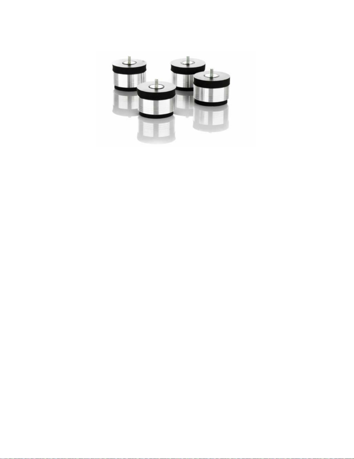
Prime 21 isolation feet
•Make space for the Prime 21 and remove the chassis from the box. Put the chassis down on a
solid surface.
The warranty does not take effect until the warranty
card is returned online as given at the end of the
manual.
•Remove the Prime 21 motor and place it in the Prime 21 cutout to the left. Be very careful not
to hit or damage the motor pulley. It measured +/- .0005” when it was tested at the factory.
Try not to disturb it at all.
•Remove the turntable platter and peel the tape of the bearing hole. Carefully lower the platter
on to the Prime 21 spindle, (there is a black cap on the spindle – remove it). The platter is
lubricated with PTFE grease and needs no maintenance for at least two years.
Setting up the Prime 21
The Prime 21 must be placed on a flat, level surface. This will make setup easy, provide better
sound quality, and put less strain on the main bearing.
•Place the turntable chassis, with the motor cutout on the left, on the shelf or stand where it will
be used. The better isolation you provide the Prime 21, the better it will sound. We highly
recommend a 1 to 3-inch-thick maple shelf sitting on rubber isolator feet for this purpose.
•Connect the power cord to the motor, put the belt around the motor pulley and platter, spin the
platter by hand and the belt will self-level.
•For 33 RPM operation, place the belt on the upper part of the pulley. For 45 RPM operation,
place the belt on the lower, wider part of the pulley. The centre groove in each diameter is the
correct speed. The optional VPI Analog Drive System (ADS) speed controller is an accessory
that provides the ultimate speed accuracy and improved sound. Check with your dealer about
availability.
•Verify the turntable is level by using a 9 or 12-inch spirit level front-to-back and side-to-side on
the platter. If it is not level, rotate the feet up or down. If there is a need to turn the Prime 21
feet more than three full turns, level the shelf or platform the table sits on first.

2
•The Prime 21 comes with 4 HW-40 Isolation feet that can be easily adjusted by turning
clockwise to raise or counter-clockwise to lower the height of your turntable.
Installing and Aligning the Cartridge
•For cartridges with threaded mounting holes, use the screws supplied by the cartridge
manufacturer. Other screws may not fit properly and may cause damage to the threads and
cartridge.
•To avoid damage to the 3D tonearm, use the provided finger lift which also serves as a washer
supplied by VPI under the screw heads and do not tighten the screws too tight.
•For cartridges with pass-through mounting holes, use the hardware supplied with the tonearm.
Be sure to use washers under the screw heads.
•The tonearm wires are colour-coded as follows:
Red tag right hot/+
Green tag right ground/-
White or Black tag left hot/+
Blue tag left ground/-
If your phono section inverts phase, the hot colour becomes the ground colour. In
this case please seek support from you VPI retailer
•Using tweezers or fine-tipped pliers, grip the centre of the red wire’s connector tag not the wire
itself and push it onto the cartridge’s right hot/+ terminal pin. Connect the remaining connectors
in the same way. To avoid damage to the cartridge, do not push the connectors all the way on.
•Place the Alignment Jig on the spindle with the V-groove against the base of the arm bearing
shaft. Tighten the screws of the jig so it fits snugly against the bearing shaft and over the record
spindle.
The arm should be placed in the arm rest when you are not playing a record!
•Line up the red dot on the Lemo connector with the red dot on the receptacle on the junction
box. The Lemo connector can plug in only one way and should not be forced.

3
•Swing the tonearm over the jig so the stylus is as close as possible to the dot in the centre of
the grid. Set the counterweight for enough downward force to keep the stylus from moving
when resting on the jig.
•Look down at the cartridge and align it between the lines of the grid. You should have the
diamond stylus on the white dot and the cantilever lined up with the lines on the grid. Use a
flashlight (torch) to look from the front and line up the cantilever with the grid lines. That is
the only alignment that matters, the cantilever lined up with the white lines and the diamond
on the white dot. The angle of the cartridge is irrelevant.
•Adjust the cartridge mounting screws and the counterweight as needed until the cartridge is
centred between the grid lines and the stylus is resting on the dot of the grid. The picture below
shows the setup, the jig is in white for clarity, yours is black.
•When the cartridge is properly positioned, tighten the cartridge mounting screws and remove
the alignment jig. Do not make them overly tight, the 3D arm is self-damping and you can
damage the surface by over tightening.

4
VIEW OF CONICAL AND LINE CONTACT STYLI AND WHY ALIGNMENT MATTERS MORE WITH THE
LINE CONTACT.
CONICAL LINE CONTACT

5
Setting the Tracking Force and Tonearm Height
Tracking force is adjusted by turning the adjustment knob left or right to move the counter weight.
If your cartridge is overly heavy and the counterweight is all the way back, you can order a heavier
weight from your dealer. Half way back is fine as is the middle third of the stub.
The Gimbal Tonearm does not have a built-in tracking force gauge but we have supplied you with
a quality digital tracking force gauge if we did not mount a cartridge for you.
•Place the gauge on the platter (no record).
•Loosen the two black thumb screws in the base of the tonearm and raise the arm so it looks
parallel to the platter when it is on the stylus force gauge. When the arm is at the desired
height, lightly tighten the thumbscrews.
•If you do not make the arm parallel when doing this, you will be between .2 to .4
grams light or heavy when you are on the record.
•Set the tracking force according to the cartridge manufacturer’s recommendation. We
recommend always going to the high side of tracking force. High frequency vibrations on a
light-tracking cartridge can cause more damage to the grooves of a record than running a
cartridge at a heavy setting. We usually recommend .1 gram higher than the max tracking
force if you are not using anti-skate (recommended way of setting). This does not apply to
Lyra cartridges that sound best at 1.73 to 1.76 grams tracking force with or without anti-
skate.
•Put a record on the platter and using the VTA tower lower the arm so it is parallel to the
record. Now you will be tracking at the force you set and not a lighter force.

6
Pivot to spindle: 258 - mm
Effective length: 273.4 - mm
Overhang: 15.4 - mm
Offset angle: 19.98 - degrees
Average RMS distortion: 0.31%
Setting the Azimuth
•Using the supplied aluminium rod placed into the groove behind the mounting screws on the
tonearm headshell.
•Azimuth is factory set to be level but you can adjust the arm wand by loosening the Azimuth
Set Screws on the side of the arm and slightly turn the wand.

7
Your azimuth should not look like this It should look like this
Setting the Anti-Skating – Two Solutions
•VPI does not support the need to have anti-skate but does respect the customer’s interest in
having it enabled. Therefore, we provide a mechanism for anti-skate and the option of engaging
it.

8
•For normal music listening all the anti-skate you need will be supplied by the lead out wire of
the tonearm to junction box unless you are using test records and measuring sine waves. For
music listening the push back of the wire is ideal for anti-skate.
•We supply mechanical anti-skate for those who require it.
If you try adjusting the anti-skate with a groove
less record, you will ruin the twist in the tonearm
wire and void your warranty. Do this with the
mechanical anti-skate if you want that much anti-
skate.
Playing Records
•Before playing a record, make sure that both of the tonearm VTA thumbscrews are slightly
tight.
•Place the black washer on the platter, then the record, then the record clamp. Always turn off
the turntable before installing the record clamp.
•Press the power button on the motor. Sit down and enjoy listening to your records!
General Use
•Allow at least 20 hours of break-in time.
•The motor will make some low-level noise. This will not get into the system. The motor and
bearings will become quieter as you use your Prime 21. Place the motor on a mouse pad for
better isolation if this bothers you.

9
•If you notice hum in the system, remove the turntable to phono section interconnects and
replace them with very cheap, standard interconnects. These are well shielded and should
eliminate the hum. If the hum goes away, get quality, well shielded interconnects.
•After at least one year of use the platter bearing should be re-lubed with PTFE super grease.
The motor will need to be lubricated with 1 drop of 40-weight motor oil below the black drive
pulley and right on the brass piece.
•You can experiment with mats but you need to adjust the VTA setting when doing this.
Additional Items Available from Your Dealer
•Prime 21 Plus which would include the VPI Weis Line by Nordost and Shyla MC Cartridge
•VPI Analog Drive System
•Periphery Ring
Possible Problems:
•Noise in the system, a hum or buzz:
oThe answer is to ground the motor and system properly. A line filter that floats the
grounds will not allow proper grounding of the phono system; the phono system must
be grounded! Phono is not like a CD player and if this is your first table or your return
to vinyl after a decade or so you must remember that phono amplification can be 1,000
times higher than CD or streaming so any noise that gets into the system will be
amplified much more. Kill the noise with proper grounding and your system will sound
better.
•A pop on motor turn on or turn off:
oIn some systems the phono section is not well shielded and will pick up the EMF created
by the switch opening to turn off the turntable. If your system is like that you can get

10
into the habit of muting (the preferred method as you should really do that) or you can
experiment with capacitors across the on-off switch. We supply the table with a .001
microfarad cap, you can change it to a .01 microfarad cap and it may eliminate to lower
the problem to a tolerable level. A judicious grounding will many times solve this
problem also.
•Trembling of tonearm when playing records:
oYou have a Gimbal tonearm, it sits on 4 bearings and is constantly moving with the
record grooves; spiralling in and out as the record centre changes and moving up and
down with minute warps. It is perfectly normal and inaudible.
•Sibilance and distortion in both channels:
oAzimuth not set correctly or diamond stylus misaligned on cartridge. This is usually a
setup or cartridge issue, not a tonearm issue. It can also be caused by a tracking force
that is too light even if it reads correctly. Tracking force needed is determined by the
temperature in the room, below 70 degrees (31 Deg Celsius) requires greater tracking
force. We have found almost all cartridges work and sound best at 72 degrees (30 Deg
Celsius).
oA small light (not cold LED) put above a turntable in a cold room will heat up the cartridge
just enough to make it much more compliant and track better.
oBefore going crazy try a slightly higher tracking force, it usually solves all the problems
and zero in on the azimuth adjustment.
oAnother possibility is probably not as bad as the next photo but will definitely cause
distortion and sibilance even in small amounts.
•Distortion in left channel:
oToo much anti-skate.
•Distortion in right channel:
oToo little anti-skate.
•Noise at startup:
oIf you get a screeching sound on startup, simply powder the drive belt with talc powder
and the noise will dissipate.

11
United states ONLY
(For all other countries please consult you retailer or local
distributor for terms and conditions of warranty)
VPI Industries, Inc. Limited Warranty
VPI Industries, Inc. (VPI) warrants this unit against defects in materials and/or workmanship for
three (3) years from the date of purchase by the original retail purchaser. VPI’s sole obligation
under this warranty is limited to the repair or replacement, at VPI’s option, of any part(s) found to
be defective. VPI’s obligation to repair or replace defective parts is the purchaser’s sole and
exclusive remedy, and VPI shall not be liable for any direct or indirect injury and/or property
damage arising out of the use of the product or defect in or failure of the product.
This warranty does not extend to any unit whose serial number has been defaced or altered. Any
product that VPI determines causes a defect or malfunction due to incorrect installation,
modification, misuse, or servicing by the purchaser, or service technician not authorized by VPI to
perform such service will not be warranted. This warranty does not cover trivial or cosmetic defects
that do not impair the unit’s normal function.
VPI reserves the right to make changes in this product without assuming any obligation to install
such change in any product previously manufactured. This warranty to repair or replace defective
parts is in lieu of all other express or implied warranties of merchantability or fitness for a particular
purpose. There are not warranties that extend beyond the description herein.
Some states do not allow exclusion of implied warranties or limitation of incidental or consequential
damages, so the above exclusion or limitations may not apply to you. This warranty gives you
specific legal rights, and you may also have other rights that vary from state to state.
Register your Product Online:
http://vpiindustries.com/warranty/
Table of contents
Other VPI Turntable manuals