:
Qa:
280733
ame:
280286
©
dams;
280372
bd
o
vstr|
Dan
-~
Dany
;
1N-8003
wW-04
o
0403:
ow
4g
:
18-4001
I
t
1
:
i
i
6
\o
tas:
Wa
:
Q)
C1
250v0.022
ORANGE
i
Fao
05aT
40g
+
1K-188
tan
1
S\O
3/8
{_
:
230V
©
Wot
Sli)
ee
2
2
!
\
3
$
wa01
i
Pag
YELLOW
—
=
ig
PB-652
|
=
1
es
R03
3.3K
©
=
i
Nests
3
=
0493
ee
{
4
Ragt
33K
27
:
f)
3
Patel
=
s
=
i
Ca
250V0.022
o
=
Ze
Fa
=
.
=
‘
AC
220/240V
4
BLACK
fe
2
EMS
BATION)
S = =
z
‘
50
Hz
jo?
9
t
|
1
proro
PB-653
©
Sem
Ooden"s
Oy
tan
Cs
©
a
©
iC
ee
A
aa
+
SWw-i
NOTES
;
pratt
199099
|
sielatenateteiatataatatetanenen
telah
otaiaies
o>
obenar
eostete
or?
ahataiatatataietatatatatatatetataratatananeten
aren
ee4
Q201~
G2
;
280945
205
;
2801447
1
1
UNLESS
OTHERWISE
SPECIFIED,
ALL
REGISTORS
ARE
IN
OHM,
'
TC
201
Daor
;
1N-4007
D202;
W-04
D203
~
D20s
;
18-4448
aw
K
=10°0HM.
ALL
CAPACITORS
ARE
IN
MICRO
FARAD;
:
Rang
1.8K
IAW
PF
=10°MICRO
FARAO,
1
Se
aes
2°
DUE
TO
CONTINUED
HESERCH
FOR
IMPROVEMENTS,
;
am
z
S
=|
[=
LUX
RESERVES
THE
RIGHT
TO
ALTER
THE
CIRCUIT
»
B20
2
s
St
PS
AND
SPECIFICATIONS
WITHOUT
NOTICE.
:
on
RS
ae
Es
23
a
«a
SSeS
|
=
=
=
Ss
8
1
235
=
zoe
2
=
=
=
!
=
=
e327
=
Sw-1
—;
POWER
SW{OFF)
t
2
=]
Ravik
==
44
C204100P
i
eed
SW-2
(ab)
;
POWER
SWiON}
1
2
0201
R206
1.8K
1/)W
Swaor
;
SPEED
SELECTOR
(33
1/4)
\
=
XK) CK)
ore
Swan
SPEED
SELECTOR
(45)
:
bs
OY
ae
t
VA
1:
SPEED
ADJUST(93
1/3)
'
5
z
=
Wiz
2-8
VR
2;
SPEED
ADJUST
(45)
\
z
g
25
2
D
x
]
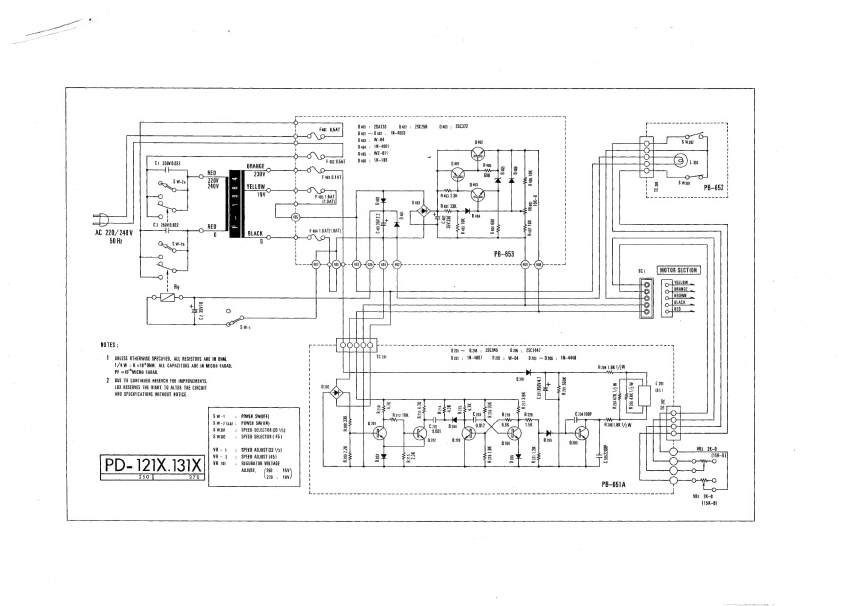
21X
131X
VA
101;
REGURATOR
VOLTAGE
:
=
= =
=
.
ADJUST,
(a
:
a
\
210:
18V
'
i
i
Leww
am
wwe
en
ene
we
ew ew
ee
ee
He
ee
nee
ewe
eee
Re
eee
ene
we
ene
we
ene
me
a
ene
ns re
enw
new
eenee
~
RI
2K-B
(15K-B)
ke
af