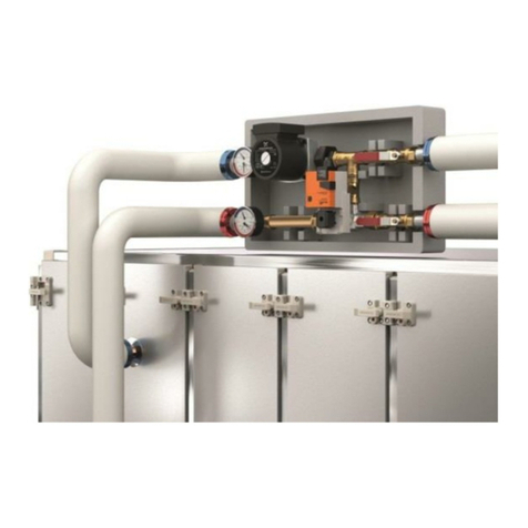
VTS Medical Systems WPG-25-070-2.5 Guide

Water pump group
Technical documentation
WPG-v.1.0 (03.2016)

1
CONTENTS
1. INTRODUCTION .............................................................................................................................................. 2
1.1. Precautions, requirements, recommendations ...................................................................................... 2
1.2. Transport and storage ............................................................................................................................. 2
2. APPLICATION AND DESIGN............................................................................................................................. 2
2.1. Technical parameters .............................................................................................................................. 4
2.2. Pump groups characteristic ..................................................................................................................... 5
3. INSTALLATION................................................................................................................................................. 6
3.1.Hydraulic installation................................................................................................................................ 6
3.2.Electric installation ................................................................................................................................... 7
4. OPERATION AND MAINTANANCE................................................................................................................... 9

2
1. INTRODUCTION
1.1. Precautions, requirements, recommendations
Detailed analysis of this documentation, as well as assembly and use of equipment, according to the
descriptions contained therein, and following all safety requirements, is the basis for the correct and safe
operation of the device.
Producer won´t be responsible for damages caused by wrong usage or unrespect of the instructions given in
this manual.
This technical documentation must be delivered together with the device. The documentation contains
information concerning all possible configurations of water pump group, examples of installation, as well as
activation, use, repair and maintenance. This instruction manual is an essential component of the product
and should be placed near the device and be readily available to the service team.
Manufacturer reserves the right to introduce changes to the instruction, as well as changes to the device
that affect its operation, without prior notice. VTS shall be are no responsibility for on-going maintenance
and damage, caused by standstills of equipment related to the waiting for warranty services, all and any
damage related to the Client’s property, other than the device in question, as well as malfunctions that
result from incorrect installation or improper use of the device.
1.2. Transport and storage
Prior to the installing and taking the device out of the cardboard box, it is required to check whether the
cardboard box has not been damaged in any way.
2. APPLICATION AND DESIGN
The water pump group it is the set of connected elements designed for control of the water heater
capacity.
The 9 sizes of pump groups is combination of 5 tree-way mixing valves with 3 sizes of water pump.
The main elements of the pump circuits that are: circulating water pump, three-way valve with actuator,
filter, and two manometers.
Fig.1. showing the simple example of application with the Air Handling unit and control elements.

3
B1 –supply temperature sensor
VFD –frequency converter
T S2F –anti frost thermostat
B3 –external temperature sensor
1Y1 –damper actuator
ΔP – pressure guard
S3F –back water temperature sensor
Y1 –3-way valve actuator
M1 –fan motor
M2 –pump motor
1 - casing
2 - thermomanometer
3 –circulation pump
4 - filter
5 –3-way valve with actuator
Fig.1. Operation diagram
All is closed in the thermal casing made of EPP. There is two sizes of casing (“S” and “L”) for 9 sizes pump
group.
Fig.2. Structure of water pump group
1 –tree-way valve with actuator, 2- pump, 3 –thermomanometer, 4- ball valve, 5 –ball valve with filter, 6 –casing

4
2.1. Technical parameters
Table.1. Dimension and connection diameter
Pump circuit type
Foam
casing
type
Circuit casing dimension [mm]
Connection diameter *
Circuit set dimension [mm]
Lc
Wc
Hc
[inch]
DN
L
W
H
WPG - 25-070 - 2.5
S
540
305
230
3/4"
20
436
135
165
WPG - 25-070 - 4.0
1"
25
448
135
176
WPG - 25-070 - 6.3
1"
25
448
135
176
WPG - 25-095 - 4.0
1"
25
448
135
182
WPG - 25-095 - 6.3
1"
25
448
135
182
WPG - 25-070 - 10
L
690
355
270
1 1/4"
32
436
191
195
WPG - 25-095 - 10
1 1/4"
32
521
191
200
WPG - 25-095 - 16
1 1/4"
32
521
191
220
WPG - 25-105 - 16
1 1/4"
32
566
191
220
*female thread diameter
Table.2.Technical data
Pump
3 way valve
Actuator
Type
mass
[kg]
Voltage
P
max.
[W]
Max.
current
[A]
Max.
water
temp.
[C]
Ambient
temp.
[C]
Max
work.
Pressure
[bar]
Overload
protection
IP
kvs
Max.
water
temp
[C]
IP
Voltage
WPG - 25-070 - 2.5
5,4
1 x 230V/50Hz
52
0,52
110
0..40
10
integrated
44
2,5
120
54
24VAC
WPG - 25-070 - 4.0
6,2
1 x 230V/50Hz
52
0,52
4
WPG - 25-070 - 6.3
6,4
1 x 230V/50Hz
52
0,52
6,3
WPG - 25-070 - 10
8,9
1 x 230V/50Hz
52
0,52
10
WPG - 25-095 - 4.0
6,6
1 x 230V/50Hz
140
1,1
4
WPG - 25-095 - 6.3
6,8
1 x 230V/50Hz
140
1,1
6,3
WPG - 25-095 - 10
10,9
1 x 230V/50Hz
140
1,1
10
WPG - 25-095 - 16
11,8
1 x 230V/50Hz
140
1,1
16
WPG - 25-105 - 16
13,7
1 x 230V/50Hz
180
1,4
16
*Additional information for the elements of the group can find in the suppliers manuals.
Table.3. Pump types used in the pump group
Pump circuit type
Used type of pump
WPG - 25-070..
UPM3 25-70 Flex AS
WPG - 25-095..
UPML 25-95 AUTO
WPG - 25-105..
UPMXL 25-105 AUTO

5
2.2. Pump groups characteristic
The below characteristic concerning to the clean water. The pumps groups may be used in heating systems
containing glycol based anti-freeze with corrosion inhibitors, up to a maximum of 35% solution. Depending
on the type of glycol, the mixture and the liquid temperature, the viscosity will increase with water as
medium. This will influence the pressure loss of the system as well as the efficiency, performance and load
of the pump.
Fig.3. Characteristics of water pump groups
0
2
4
6
8
0 1 2 3 4 5
H [m]
Q [m3/h]
WPG - 25-70
WPG -25-070 - 2,5
WPG - 25-70 - 4
WPG - 25-70 - 6,3
WPG - 25-70 - 10
0
2
4
6
8
10
012345678
H [m]
Q [m3/h]
WPG - 25-95
WPG - 25-95 - 4
WPG - 25-95 - 6,3
WPG - 25-95 - 10
WPG - 25-95 - 16
0
5
10
15
012345678
H [m]
Q [m3/h]
WPG - 25-105
WPG - 25-105 - 16

6
3. INSTALLATION
3.1.Hydraulic installation
The water pump group must always be installed where the pump motor shaft is in the horizontal position.
Before installing the system should be flushed out thoroughly to clear all foreign matter such as solder,
steel wool, copper filings.
The pump group must be connected to the installation with thermomanomeher from the water heater side
and valves from the net side, like in the below example.
Connection to the exchanger and installation should be carried out so as not to allow for stresses which
may result in mechanical damages or leakage. The pipeline should be supported in some place to avoid the
pass of weight and thermal stresses onto the exchanger's connections.
Ends of the groups are ended with an internal thread. To provide the seal, connection should be made with
using teflon tape or other sealing material. During assembly of the system to the pump groups, counter the
connection with additional wrench.
Fig.4. Example of installation
The pipe lines and place of water pump group should be planned so as it does not collide with the other
AHU sections and make possible inspection them without necessity disassembly.
Applied method of pump group installation with the supply system should allow for an easy pipeline
disassemble in order to remove the exchanger from the AHU.
Below drawing shows the available positions.
Fig.5. Position of the water pump group.

7
Group cannot be subjected to very high temperatures, such as occur during eg. welding or soldering. It
should be installed only after the finished such work.
After assembly of the group, pressure test must be performed in order to check the tightness in the
threaded connections.
After connection water pump group to the installation make electrical connection of the pump and valve
actuators and assembly the casing.
3.2.Electric installation
The electrical connection should be carried out by an authorized electrician in accordance with local
regulations.
Do not remove motor terminal box covers, electrical cables or any other electrical protective
covering without first ensuring that the electrical supply is suitably isolated. Do not attempt to
supply electricity to the pump without ensuring that all electrical fittings, cables and enclosures
are intact and suitably electrically isolated from human touch during operation.
Electric connection for the pump
The pump requires no external motor protection. Check that the supply voltage and frequency correspond to the values
stated on the nameplate.
The pump must not be used with an external speed control which varies the supply voltage, for example phase-cut or
pulse-cascade control.
The supplied pumps are delivered with molex 3-pin plug and cable to moved out of the pump group casing. Connect
power supply to the three leads L, N and PE.
The cable size to be used is 3 core 0.75mm2. The cable should be capable of withstanding a minimum
temperature of 100°C.
Line/phase: L (brown)
Neutral : N (blue)
Protective earth: (yellow/green )

8
Electric connection for the valve actuator
To make electrical connection of the valve actuator use cable 3x 075mm2 according to below scheme
In the any other option refer to the manual delivered with valve actuator.
Both of them can be connected to VTS control system in case of ordering VTS AHU with full automation.
Notes
11. Connect via safety isolation transformer.
12. Direction of rotation switch is covered.
Factory setting: Direction of rotation Y2
Control of controller
Meassuring voltage for reset
signal
Direction of rotation
Wiring diagram Standard connection

9
4. OPERATION AND MAINTENANCE
Start-up of the pump
Do not start the pump until the system has been filled with liquid and vented. Being self-venting, the rotor
can does not require venting before start-up. Air inside the pump will be transported by the medium into
the system during the first minutes after pump start-up.
The system cannot be vented through the pump. As the pump is self-venting, it does not need to be vented
before start-up. However, besides the smallest pump 25-70, it is recommended to vent pumps installed in
systems where the pumped medium is very dirty, as well as after service of the pump. The screw may be
loosened to check if the system has been vented completely.
When loosening the air-venting/de-blocking screw, be aware of hot, spraying water.
The operation of the pump depend on the type used in the water pump group (Table.3).
UPM3 25-70 Flex AS - The user interface is designed with a single push button, one red/green LED and four yellow LEDs.
The user interface shows:
• performance view (during operation)
–operation status
–alarm status
• settings view (after pressing the button).
During operation, the display shows the performance view. If you press the button, the user interface switches the view or runs in
the setting selection mode. The performance view shows either the operation status or the alarm status.
When the circulator is running, LED 1 is green. The four yellow LEDs indicate the current performance as the percentage of P Max.
(0- one LED green, 0-25% - one LED green + one yellow, 25-50 –one LED green + two yellow LED, and adequately for 50-75, 75-100.
When the operation mode is active, all active LEDs are constantly on in order to differentiate this mode from the select setting
mode. If the circulator is stopped by an external signal, LED 1 flashes green.
Alarm status
If the circulator has detected one or more alarms, the bi-colored LED 1 switches from green to red. When an alarm is active, the
LEDs indicate the alarm type as defined in the table below. If multiple alarms are active at the same time, the LEDs only show the
error with the highest priority. The priority is defined by the sequence of the table.
When there is no active alarm anymore, the user interface switches back to operation mode.
Display
Indication
Pump operation
Counter action
One red LED + one
yellow LED (LED 5)
Rotor is
blocked.
Trying to start
again every 1.33
seconds.
Wait or deblock
the shaft.
One red LED +
one yellow LED
(LED 4)
Supply
voltage too
low.
Only warning,
pump runs.
Control the
supply voltage.
One red LED +
one yellow LED
(LED 3)
Electrical
error.
Pump is stopped
because of low
supply voltage or
serious failure.
Control the
supply voltage /
Exchange the
pump.
Push button LEDs

10
Settings view
You can switch from the performance view to the settings view by pressing the push button. The LEDs indicate the actual setting.
The settings view shows which mode controls the circulator. No settings can be made at this stage. After 2 seconds, the display
switches back to performance view.
If LED 1 is green, it indicates operation or internal control. If LED 1 is red, it indicates alarm or external control. LED 2 and 3 indicate
the different control modes and LED 4 and 5 indicate the different speeds.
LED 1
LED 2
LED 3
LED 4
LED 5
Proportional pressure
Green
+
Constant pressure
Green
+
Constant curve
Green
+
+
Speed 1
Speed 2
+
Speed 3
+
+
Key lock function
The purpose of the key lock function is to avoid accidental change of settings and misuse. When the key lock function is enabled, all
long key presses will be ignored. This prevents the user from entering the "select setting mode" area and allows the user to see the
"show setting mode" area. If you press the key lock for more than 10 seconds, you can toggle between enabling/disabling the key
lock function. When doing so, all LEDs, except for the red LED, will flash for a second indicating that lock is toggled.
UPML 25-95 AUTO and UPMXL 25-105 AUTO - The user interface allows to select between 6 control
curves in two control modes:
• three proportional pressure curves (PP)
• three constant pressure/power curves (CP).
LED indication of the curve setting CP and PP curves
Factory presetting
Proportional pressure curve, PP2:
• Push the button for two seconds:
–Pump goes to setting mode - LED starts flashing.
• With each push, the setting changes:
–LED 1-2-3 are permanently on, and then the
control curve and mode is changed.
• Flashing mode:
–Fast: Proportional pressure
–Slow: Constant pressure/power
• After ten seconds not pushing the button:
–Setting is adapted.
–Pump returns to operating mode
• LED 1 or 2 or 3 is permanently on.
–Pump is running with the selected curve and
mode.
For detailed information refer to the pump supplier documentation.
Maintenance of the pump group comes to periodic checking and cleaning of strainer filter.

1
The pump does not require any maintenance during service life, since pump bearings are water lubricated.
It is recommended that the pump be switched on for a few minutes each week whenever the system is not
in use, to prevent sediment build-up in the pump.
If the pump has been inoperative for a long period, i.e., during Summer season, it is advisable to check the
pump shaft for free rotation before switching on. Close isolating valves and unscrew and remove the vent
plug. Locate a small screwdriver 3 mm into the end of the shaft, push gently and rotate several times in
each direction. Close vent plug and retighten.
Fault finding
Fault
Cause
Remedy
Pump is not running. No
power supply.
System is switched off.
Check the system controller.
A fuse in the installation is blown.
Replace the fuse.
The circuit breaker has tripped.
Check the power connection and switch on the circuit
breaker.
Power supply failure.
Check the power supply
Pump is not running. Normal
power supply.
Controller is switched off.
Check the controller and its settings.
Pump is blocked by impurities.
Remove impurities. Deblock the pump from the front of
the control box with a screwdriver
Pump is defective.
Replace the pump.
Noise in the system
Air in the system
Vent the system.
Differential pressure is too high.
Reduce the pump performance at the pump
Air in the pump.
Let the pump run. The pump vents itself over time.
Noise in the pump
Inlet pressure is too low.
Increase the system pressure or check the air volume in the
expansion tank, if installed.
Insufficient flow.
Pump performance is too low.
Hydraulic system is closed or system pressure
is insufficient.
Check the pump settings.
Check the non-return valve and filter. Increase the system
pressure.
Actuator does not open the valve
1. There is mistake in electrical connection
1. Check correctness of electrical connections
2. Wrong settings in the main controller
2. Check operational correctness of the control signal
3. Wrong parameters of the power supply
3. Check parameters of the supply current (among others:
voltage).
It is forbidden to place, dispose of and store worn-out electric and electronic equipment,
together with other waste. Dangerous compound contained in electronic and electric
equipment have a very adverse impact on plants, micro-organisms, and, most importantly, on
humans, as they damage our central and peripheral nervous system, as well as circulatory and
internal system. Additionally, they cause serious allergic reactions. Worn-out equipment is to
be delivered to a local collection point for used electric equipment, which carries out a
selective collection of waste.
REMEMBER!
The user of equipment intended for households, and which has been worn out, is obliged to
transfer such equipment to a collecting unit that collects worn-out electric and electronic
equipment. The selective collecting and further processing of waste from households
contributes to the protection of environment, reduces the penetration of hazardous
substances into the atmosphere and surface waters.

Water pump group
Electrical installation and warranty card
Grupa pompowa
Instalacja elektryczna I karta gwarancyjna
Šunta mezgls
Elektroinstalācija un garantijas karte
Veepumbagrupp
Elektripaigaldis ja garantiikaart
Szivattyú egység
Elektromos telepítés és garancialap
Směšovací uzel
Elektrické zapojení a záruční list
Vandens siurblio grupė
Elektros instaliacija ir garantinė kortelė
EN
PL
LV
ET
HU
CZ
LT
WPG-v.1.0 (04.2016)


CONTENTS
1. ELECTRIC INSTALLATION ...................................................................................... 2
2. WARRANTY CARD ................................................................................................... 9
SPIS TREŚCI
1. INSTALACJA ELEKTRYCZNA................................................................................. 3
2. KARTA GWARANCYJNA.......................................................................................10
SATURS
1. ELEKTROINSTALĀCIJA ........................................................................................... 4
2. GARANTIJAS KARTE .............................................................................................11
SISUKORD
1. ELEKTRIPAIGALDIS.................................................................................................. 5
2. GARANTIIKAART....................................................................................................12
TARTALOMJEGYZÉK
1. ELEKTROMOS TELEPÍTÉS ...................................................................................... 6
2. GARANCIAPAPÍR....................................................................................................13
OBSAH
1. ELECTRICKÉ ZAPOJENÍ.......................................................................................... 7
2. ZÁRUČNÍ LIST .........................................................................................................14
TURINYS
1. ELEKTROS INSTALIACIJA....................................................................................... 8
2. GARANTINĖ KORTELĖ..........................................................................................15
EN
PL
LV
ET
HU
CZ
LT
1

EN
1. ELECTRIC INSTALLATION
The electrical connection should be carried out by an authorized electrician in
accordance with local regulations. Do not remove motor terminal box covers,
electrical cables or any other electrical protective covering without first ensuring
that the electrical supply is suitably isolated. Do not attempt to supply electricity
to the pump without ensuring that all electrical fittings, cables and enclosures are
intact and suitably electrically isolated from human touch during operation.
Electric connection for the pump
The pump requires no external motor protection. Check that the supply voltage and frequency
correspond to the values stated on the nameplate.
The pump must not be used with an external speed control which varies the supply voltage,
for example phase-cut or pulse-cascade control.
The supplied pumps are delivered with molex 3-pin plug and cable to moved out of the pump
group casing. Connect power supply to the three leads L, N and PE.
Line/phase: L (brown
Neutral : N (blue)
Protective earth: (yellow/green )
The cable size to be used is 3 core 0.75mm2. The cable should be capable of withstanding a
minimum temperature of 80°C.
Electric connection for the valve actuator
To of the valve actuator use cable 3x 075mm2 according to make electrical connection below
scheme.
Wiring diagram Standard connection
Notes
• Connect via safety isolation transformer.
• Direction of rotation switch is covered.
Factory setting: Direction of rotation Y2
DC 0 ... 10 V
Control of controller
Direction of rotation
Measuring voltage
for reset signal
Y
Y1
Y2
+
~
T
-
U
1 2 3 5
DC 2 ... 10 V
In the any other option refer to the manual delivered with valve actuator.
Both of them can be connected to VTS control system in case of ordering VTS AHU with full
automation.
2

PL
1. INSTALACJA ELEKTRYCZNA
Podłączenie elektryczne winno być wykonane przez wykwalifikowanego elektryka
zgodnie z obowiązującymi przepisami. Nie zdejmuj pokrywy skrzynki zaciskowej
silnika, bez uprzedniego upewnienia się, że zasilanie elektryczne jest odłączone.
Nie włączaj zasilania przed upewnieniem się, że wszystkie połączenia elektryczne,
kable i obudowy są prawidłowo zabezpieczone przed dotykiem podczas pracy.
Podłączenie elektryczne pompy
Pompa nie wymaga żadnej zewnętrznej ochrony silnika. Należy sprawdzić, czy napięcie i
częstotliwość w sieci zasilającej są zgodne z wartościami podanymi na tabliczce znamionowej.
Pompa nie może być używana z zewnętrznym sterowaniem prędkości, który zmienia napięcie
zasilania, na przykład sterowaniem typu obcięcie faz lub pulsacyjno-kaskadowym.
Stosowane pompy są dostarczane z 3 pinową złączką i kablem dla wyprowadzenia poza
obudowę zespołu. Zasilanie podłączyć do trzech przewodów l, N i PE.
Faza: L (brązowy)
Neutralny : N
Uziemienie: (żółto-zielony)
Kabel używany do podłączenia zasilania pompy: 3x0,75mm2. Przewód powinien być odporny
na temperaturę otoczenia min. 100 ° C.
Podłączenie elektryczne siłownika zaworu
Do podłączenie siłownika wymagany jest kabel 3x 075mm2. Siłownik podłączyć wg
poniższego schematu.
Schemat połączeń Połączenie standardowe
Uwaga
• Podłączać poprzez transformator bezpieczeństwa.
• Przełącznik kierunku obrotu jest zakryty.
Ustawienie fabryczne: Kierunek obrotu Y2
DC 0 ... 10 V
Sygnał nastawczy z regulatora
Kierunek obrotu
Napięcie pomiarowe
do resetowania
Y
Y1
Y2
+
~
T
-
U
1 2 3 5
DC 2 ... 10 V
Dla innych opcji zasilania patrz instrukcja siłownika.
Zarówno pompa jak i siłownik mogą być podłączone do system automatyki VTS (w przypadku
opcji zamówienia z pełną automatyką).
3

LV
1. ELEKTROINSTALĀCIJA
Elektriskais pieslēgums jāveic kvalificētam elektriķim saskaņā ar piemērojamiem
noteikumiem. Nenoņemt vākus motora spaiļu kārbām, elektriskos kabeļus un
jebkādu citu elektrisko aizsargpārklājumu, iepriekš nepārliecinoties, ka strāvas
padeve ir atslēgta. Neieslēgt sūkņa energoapgādi, ja nav nodrošināts, ka visi
elektriskie savienojumi, kabeļi un korpusi ir pienācīgi aizsargāti pret nejaušu
kontaktu darbības laikā.
Sūkņa elektriskie savienojumi
Sūknim nav nepieciešama ārēja motora aizsardzība. Jāpārbauda, vai barošanas spriegums un
frekvence atbilst pases datu plāksnītē norādītajām vērtībām.
Sūkni nedrīkst izmantot ar ārēju ātruma regulatoru, kas maina barošanas spriegumu,
piemēram, kontrolē rotācijas fāzi vai ieslēdz impulsveida kaskādes vadību.
Piegādāto sūkņu komplektācijā ir «Molex» 3 tapiņu spraudnis un no sūkņa grupas korpusa
izvadīts kabelis. Energoapgāde jāsavieno ar trīs vadiem: L, N un PE.
Līnija/fāze: L (brūns)
Neitrāle: N (zils)
Aizsargzemējums: (dzeltens/zaļš)
Lietojams trīsdzīslu kabelis, kura šķērsgriezums ir 0,75 mm². Kabelim jāspēj izturēt 100 °C
minimālo temperatūru.
Vārsta piedziņas elektriskais savienojums
Lai izveidotu vārsta elektrisko savienojumu, lietojams 3 x 0,75 mm² kabelis saskaņā ar zemāk
doto shēmu
Elektriskā shēma Standarta savienojums
Piezīmes
• Jāsavieno, izmantojot atdalītājtransformatoru.
• Slēdža rotācijas virziens ir pārklāts.
Izgatavotājuzņēmuma iestatījums: Rotācijas virziens Y2
DC 0 ... 10 V
Regulatora vadības signāls
Rotācijas virziens
Mērīšanas spriegums
atiestatīšanai
Y
Y1
Y2
+
~
T
-
U
1 2 3 5
DC 2 ... 10 V
Jebkura cita varanta gadījumā skatīt ar vārsta piedziņu piegādātajā instrukcijā.
Gan sūkni, gan piedziņu var savienot ar VTS vadības sistēmu, pasūtot VTS gaisa apstrādes
iekārtu ar pilnu automātiku.
4

ET
1. ELEKTRIPAIGALDIS
Elektriühendused peab teostama volitatud elektrik vastavalt kohalikele
eeskirjadele. Ärge eemaldage mootori klemmikarbi katteid, elektrikaableid ega
muid elektriosade kaitsekatteid enne, kui olete veendunud, et vooluvarustus on
nõuetekohaselt katkestatud. Ärge lülitage pumba elektrivarustust sisse enne, kui
olete veendunud, et kõik elektriseadmed, kaablid ja ümbrised on terved ning neil
on nõuetekohane talitluse ajal inimesi kokkupuute eest kaitsev elektriisolatsioon.
Pumba elektriühendus
Pump ei vaja välist mootorikaitset. Veenduge, et toitevool ja -sagedus vastaksid andmeplaadil
olevatele väärtustele.
Pumpa ei tohi kasutada toitepinget muutva välise kiiruseregulaatoriga, näiteks releelüliti või
impulss-kaskaadregulaatoriga.
Pumbad tarnitakse koos kolme kontaktiga Molex-pistiku ja kaabliga, mis juhitakse pumbagrupi
korpusest välja. Ühendage toite kaabel kolme juhtmega: L, N ja PE.
Liin/faas: L (pruun)
Neutraal: N (sinine)
Maandus: (kollane/roheline)
Kasutada tuleb kolme 0,75 mm2 südamikuga kaablit. Kaabel peab taluma vähemalt 100 °C
temperatuuri.
Klapiajami elektriühendus
Kasutage klapiajami elektriühenduse tegemiseks 3 x 0,75 mm2 kaablit vastavalt allolevale
skeemile.
Elektriskeem Standardühendus
Märkused
• Tehke ühendus läbi kaitsetrafo.
• Pöörlemissuuna lüliti on kinni kaetud.
Tehaseseadistus: pöörlemissuund Y2
DC 0 ... 10 V
Kontrolleri juhtsignaal
Pöörlemissuund
Lähtestamissignaali
mõõtepinge
Y
Y1
Y2
+
~
T
-
U
1 2 3 5
DC 2 ... 10 V
Lisavõimaluste kohta lugege klapiajami juhendist.
VTSi täisautomaatse ventilatsiooniseadme tellimise korral on võimalik need mõlemad
ühendada VTSi juhtimissüsteemiga.
5

HU
1. ELEKTROMOS TELEPÍTÉS
Az elektromos bekötéseket megfelelő képesítésekkel ellátott szakembernek az
ide vonatkozó szabványok, előírások betartásával kell elvégezni. A bekötések,
gyári csatlakozások vagy elektromos kábelek megbontása előtt minden esetben
győzödjön meg arról, hogy az eszköz leválasztásra került az elektromos hálózatról.
Ne próbálja meg áram alá helyezni a szivattyút mielőtt az összes elektromos
csatlakozás megfelelően kiépítésre, bekötésre nem került ezáltal elkerülve az
áramütés kockázatát vagy anyagi kár keletkezését.
Elektromos csatlakozások a szivattyúhoz
A szivattyú nem igényel külső motorvédelmet. Ellenőrizze, hogy a betáp feszültsége
megegyezik az adattáblán találhatóval.
A szivattyú esetén nem használható külső fordulatszám szabályzás mely változtatja a
tápfeszültséget, pl. fázis vágó és fázis változtató szabályzás.
A szivattyúk bekötve, 3 pines molex csatlakozóval kerülnek szállításra mely már kivezetésre
került az egységen kívülre. A kábeleket a jelöléseknek megfelelően kell bekötni.
Fázis: L (barna)
Nulla: N (kék)
Védőföld: (zöld-sárga)
A csatlakozó kábel keresztmetszete 3x0,75 mm2. A kiépített elektromos kábeleknek minimum
80°C-nak ellen kell állnia.
Elektromos csatlakozások a háromjáratú mozgatóhoz
A háromjáratú mozgatóhoz szükséges kábel keresztmetszete 3x0,75 mm2 az alábbi ábrának
megfelelően.
Bekötési ábra Alap bekötés
Megjegyzés
• Az üzemhez megfelelően biztosított trafó szükséges.
• A forgásirány el van takarva. Az alap forgásirány Y2.
DC 0 ... 10 V
Vezérlő feszültség
Forgásirány
Állapot visszajelzés
Y
Y1
Y2
+
~
T
-
U
1 2 3 5
DC 2 ... 10 V
Minden egyes opció háromjáratú testtel és mozgatóval kerül leszállításra.
Mind a szivattyú, mint a háromjáratú csatlakoztatható a VTS által szállított automatikához
amennyiben az megrendelésre került.
6
This manual suits for next models
8
Table of contents
Other VTS Medical Systems Water Pump manuals
Popular Water Pump manuals by other brands

Salamander Pumps
Salamander Pumps CT Force installation guide

Davey
Davey M5138 Installation and operating instructions

GORMAN-RUPP
GORMAN-RUPP T4A3-B Installation, operation and maintenance manual

moyno
moyno G2 Service manual

Crane
Crane 4SHM Installation and operation manual

Sicce
Sicce Syncra HF instructions