TABLE OF CONTENTS
Page
1-1. INTRODUCTION ........................................... 1
1-2. GENERAL............................................... 1
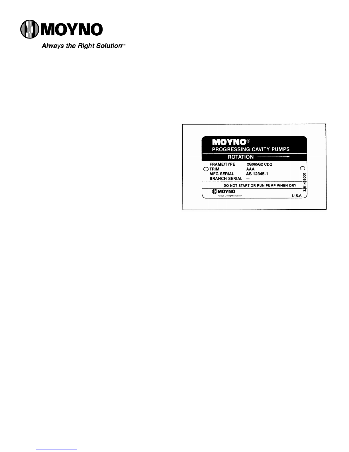
1-3. NAMEPLATE DATA ...............................1
1-4. Pump Rotation................................ 1
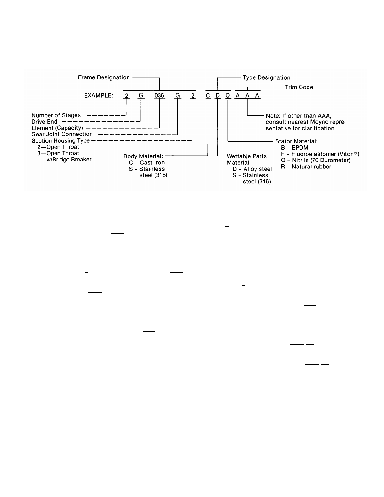
1-5. Model Number................................ 1
1-6. Frame Size Designation................. 1
1-7. Type Designation............................ 1
1-8. Trim Code....................................... 2
1-9. Variation of Standard Parts............ 2
2-1. INSTALLATION............................................. 2
2-2. GENERAL............................................... 2
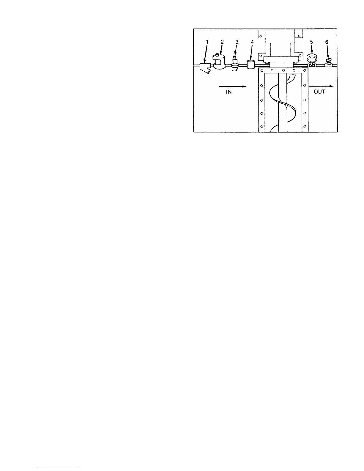
2-3. PIPING................................................... 2
2-4. Suction Hopper............................... 2
2-5. Discharge Piping ............................ 2
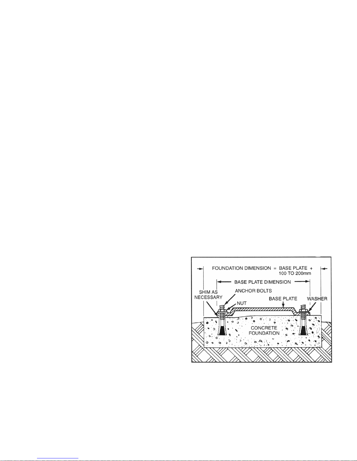
2-6. FOUNDATION........................................ 2
2-7. SHAFT ALIGNMENT.............................. 3
2-8. On Coupling Connected Units........ 3
2-9. On Belt Drive Units......................... 3
2-10. WATER FLUSH OF PACKING............. 3
3-1. OPERATION................................................... 3
3-2. INITIALCHECK....................................... 3
3-3. START-UP.............................................. 3
3-4. PACKING LEAKAGE.............................. 4
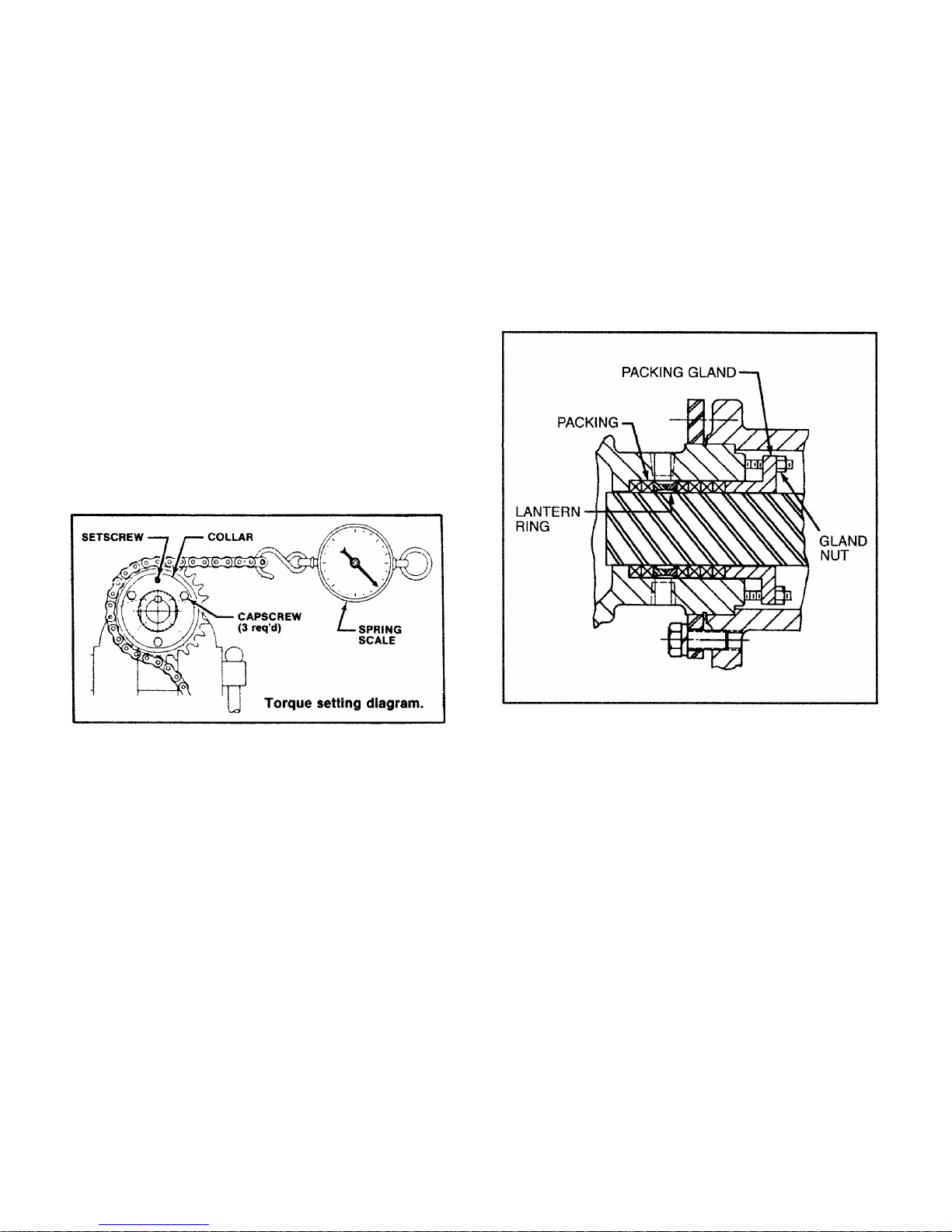
3-5.G3 DRIVE ASSEMBLY ADJUSTMENT.. 4
4-1. MAINTENANCE ............................................. 4
4-2. GENERAL............................................... 4
4-3. PACKING ADJUSTMENT ...................... 4
4-4. PACKING REPLACEMENT ................... 4
4-5. LUBRICATION........................................ 5
4-6. Bearings ......................................... 5
4-7. Gear Joints ..................................... 5
4-8. G3 Oilers ........................................ 5
4-9. DISASSEMBLY OF G2 OPEN THROAT
PUMP..................................................... 5
4-10. Disconnect Pump ......................... 5
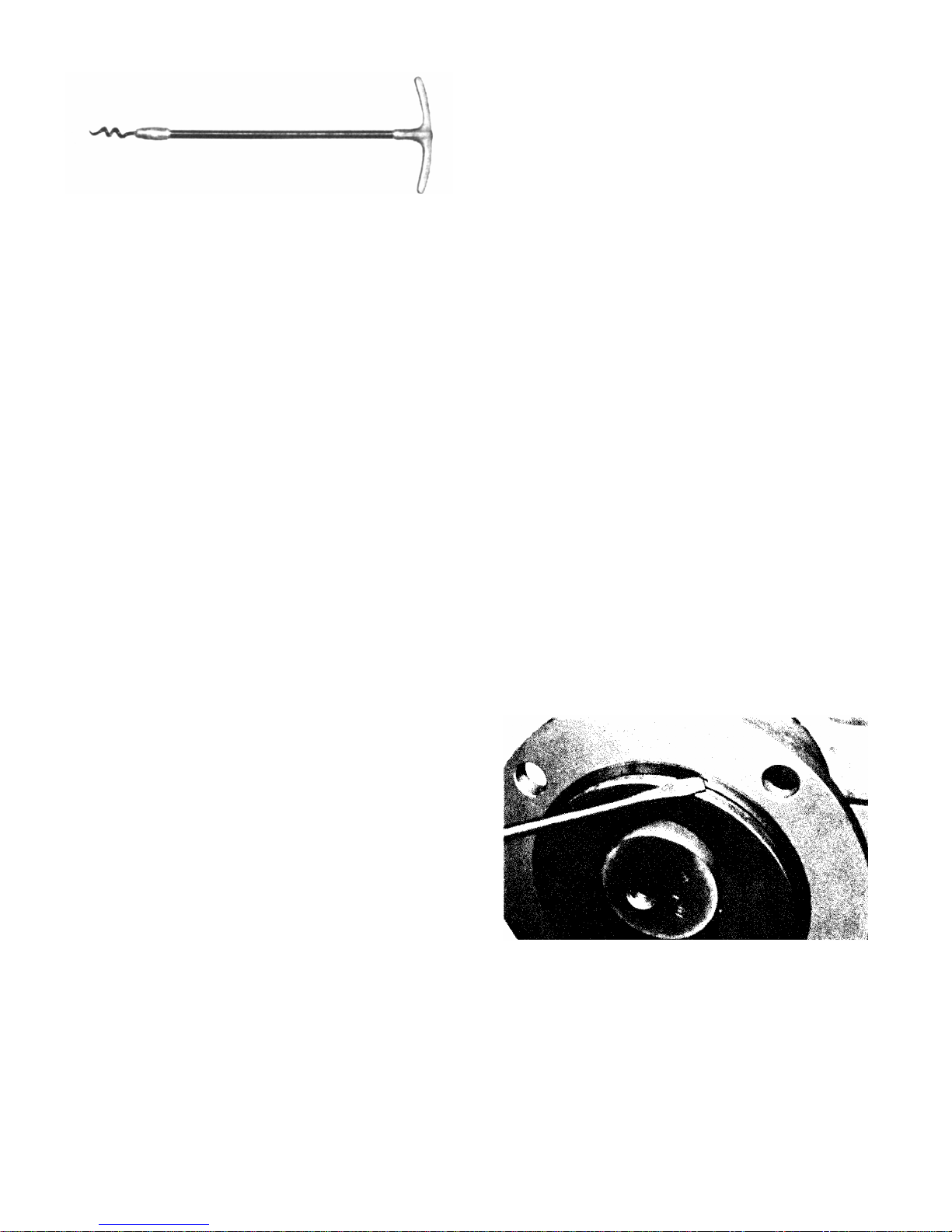
4-11. Packing Removal.......................... 5
4-12. Stator Removal............................. 5
4-13. Rotor Removal.............................. 6
4-14. Gear Joints and Conveyor Assembly
Removal ...................................... 6
4-15. Drive Shaft and Bearings Removal6
4-16. DISASSEMBLY OF G3 BRIDGE
BREAKER............................................ 6
4-17. Disconnect Pump........................6
4-18. Chain Replacement .................... 6
4-19. Torque Limiter Removal ............. 6
4-20. Shaft Gears Removal.................. 6
4-21. Breaker End Shafts or Paddle
Assembly Removal..................... 7
4-22. Drive Assembly Shafts Removal... 7
4-23. Packing Removal........................7
Page
4-24. CLEANING...................................................7
4-25. INSPECTION................................................7
4-26. Bearings..............................................7
4-27. Shafts..................................................7
4-28. Seals ...................................................7
4-29. Packing................................................7
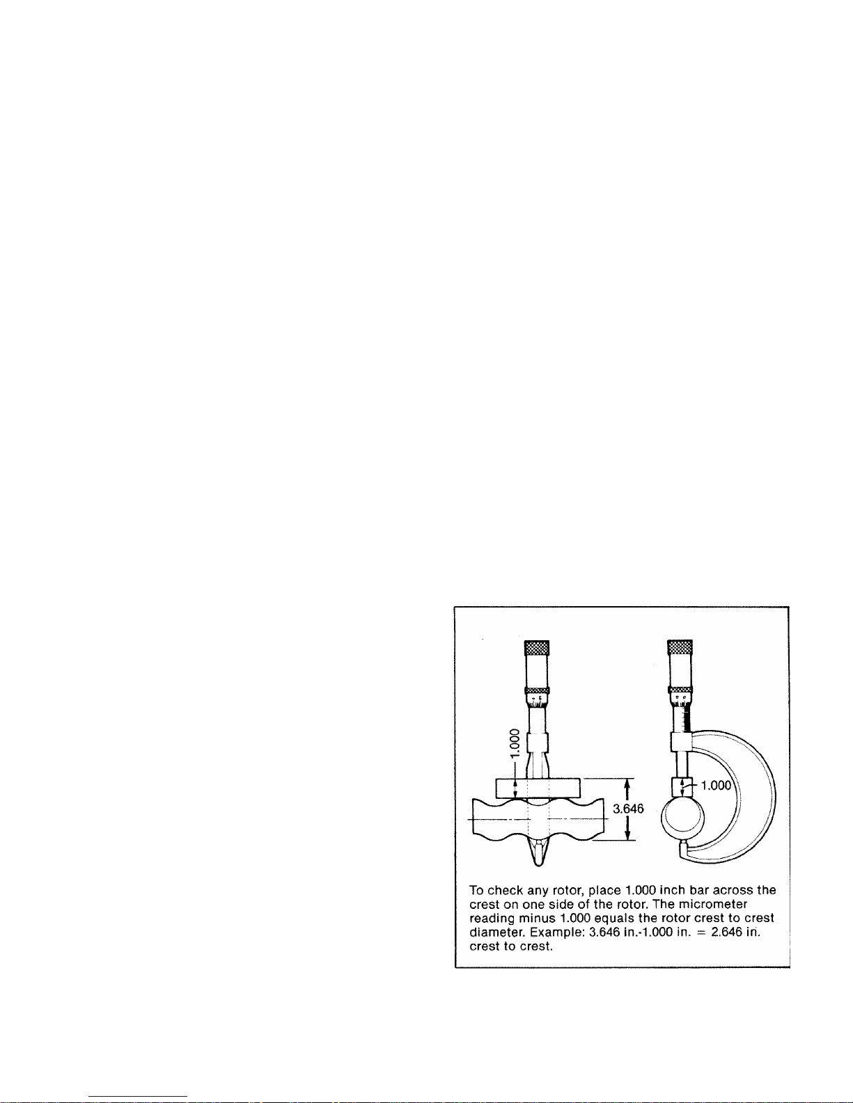
4-30. Rotor....................................................8
4-31. Stator...................................................8
4-32. All Other Parts.....................................8
4-33. ASSEMBLY OF G2 OPEN THROAT PUMP .....8
4-34. Lubrication During Assembly ..............8
4-35. Packing Installation .............................8
4-36. Bearing Housing/Suction Housing
Assembly ............................................9
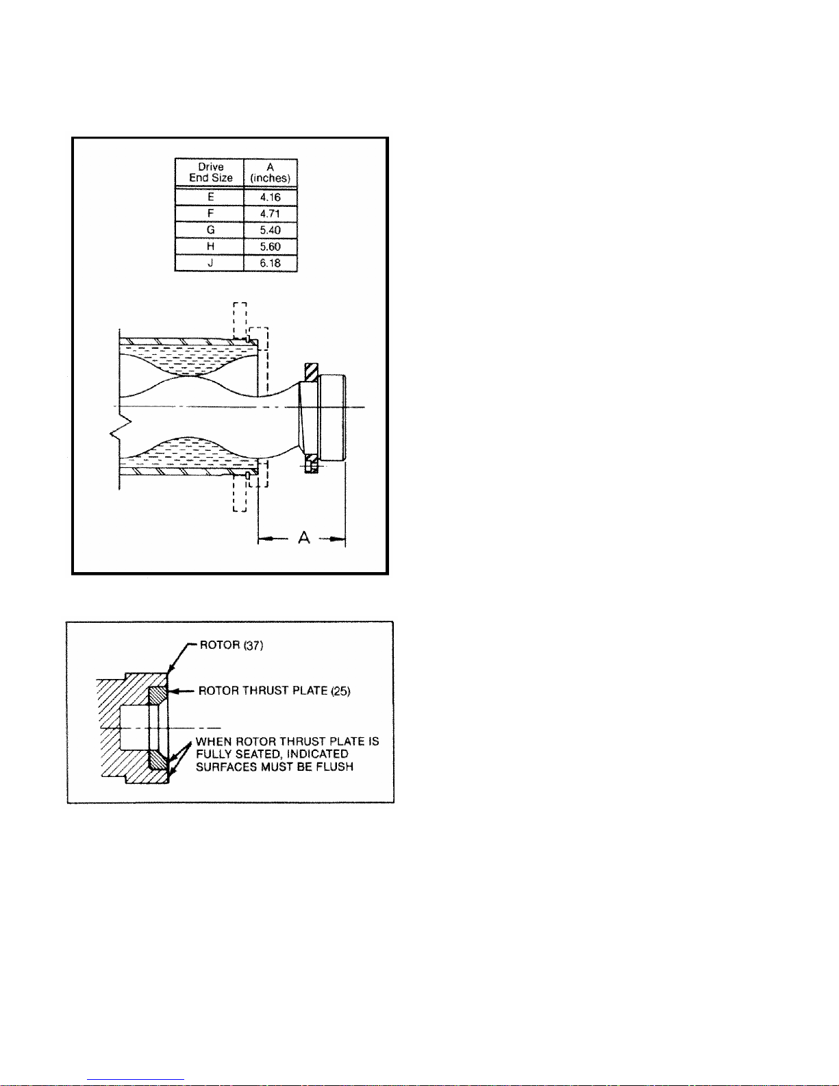
4-37. Bearing/Drive Shaft Assembly ............9
4-38. Rotor/Stator Assembly........................9
4-39. Rotor Gear Joint and Conveyor
Assembly ...........................................10
4-40. Drive End Gear Joint Assembly.........11
4-41. Stator Support/Discharge
Assembly ...........................................11
4-42. Final Assembly...................................11
4-43. Packing Adjustment ...........................11
4-44. ASSEMBLY OF G3 BRIDGE BREAKER.....11
4-45. Suction Flange Installation.................11
4-46. Packing Installation ............................11
4-47. Mounting Bearings .............................11
4-48. Paddle Assembly Installation.............12
4-49. Drive Assembly Installation................12
4-50. Final Assembly...................................12
4-51. STORAGE....................................................12
4-52. Short Term Storage............................12
4-53. Long Term Storage ............................12
4-54. PACKING SPECIFICATION........................13
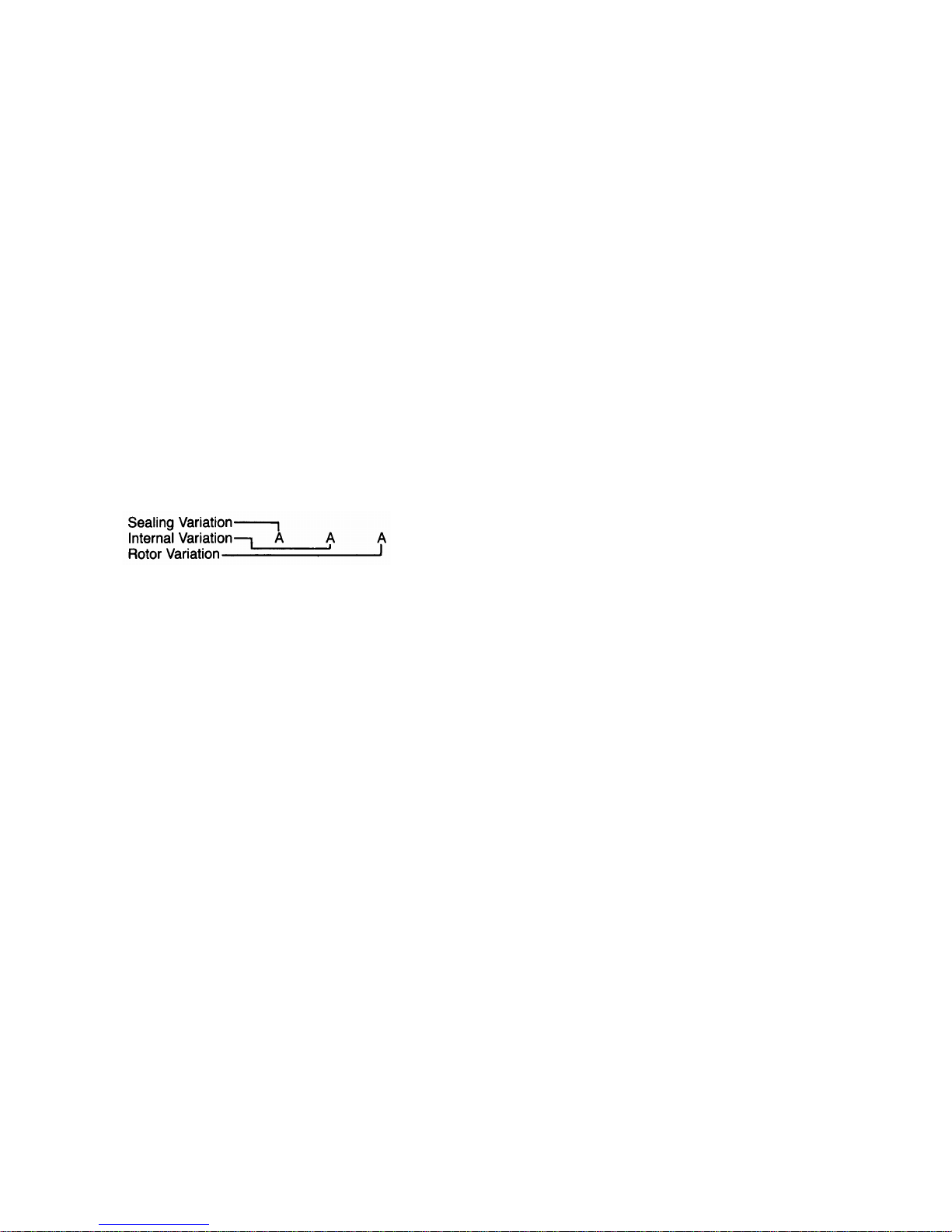
4-55. VARIATIONS OF STANDARD PARTS .......13
4-56. Rotors.................................................13
4-57. Drive Shafts........................................13
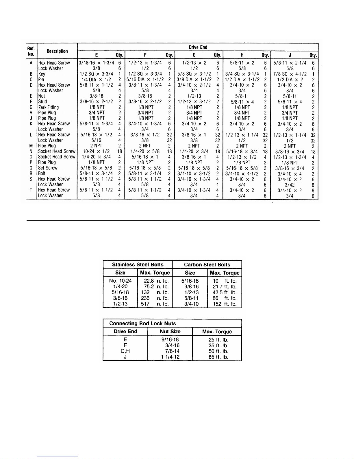
4-58. STANDARD HARDWARE FOR G2 OPEN
THROAT......................................................14
4-59. SELECTING THE CORRECT PART...........15
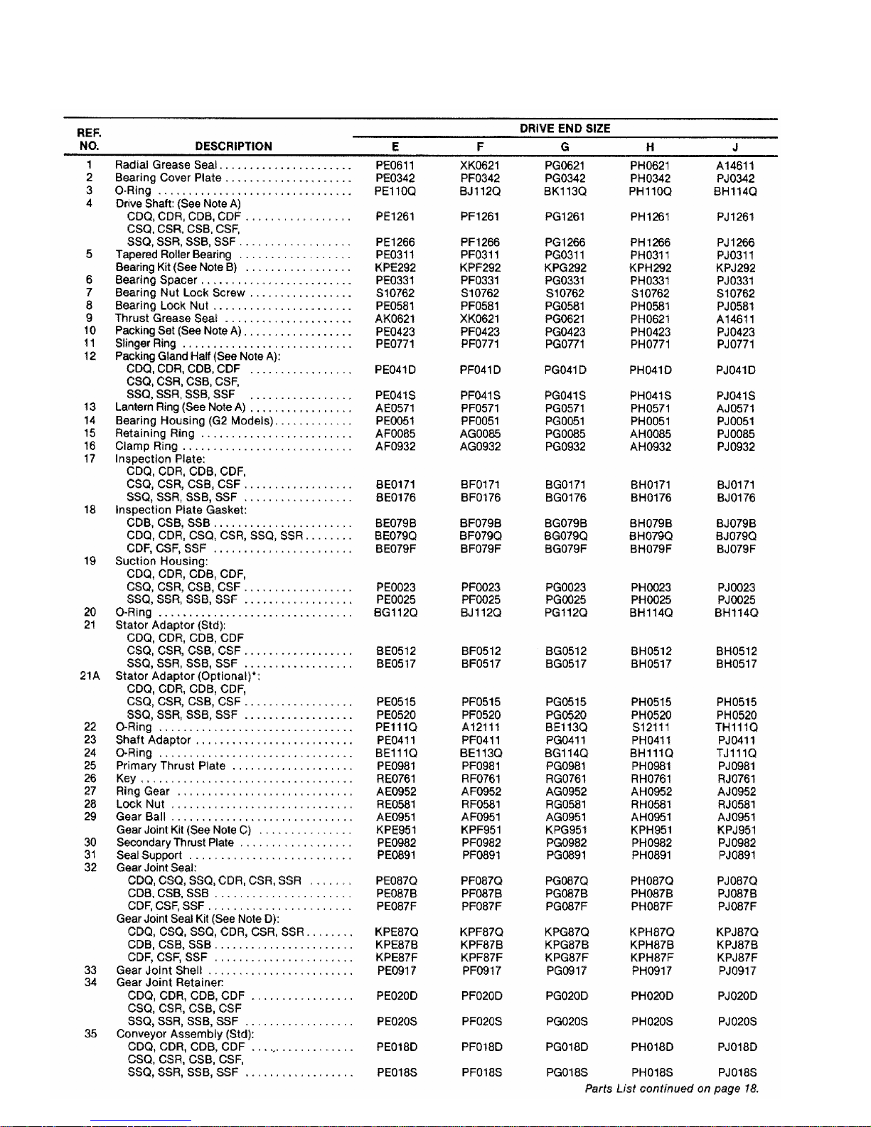
4-60. PARTS LIST FOR G2 OPEN THROAT.......16
4-61. STANDARD HARDWARE FOR G3 BRIDGE
BREAKER ...................................................20
4-62. PARTS LIST FOR G3 BRIDGE BREAKER....20
4-63. CONVERSION FROM G2 TO G3................22
4-64. SHAFT SLEEVE ARRANGEMENT.............24
4-65. Disassembly.......................................24
4-66. Assembly............................................24
4-67. TROUBLESHOOTING.................................25
Note: This service manual outlines installation, operation and maintenance proce-
dures for the open throat “G2” and bridge breaker “G3” models of the Moyno
2000 pump. For information on the flanged (G1) models of the Moyno 2000
pump, refer to the G1 Service Manual, or contact your nearest Moyno pump
representative.