Walker H37i User manual

Operator’s Manual
Safety, Assembly, Operating, and Maintenance Instructions
Please Read and Save These Instructions
For Safety, Read All Safety and Operation
Instructions Prior to Operating Machine
Beginning S/N: 174903
P/N 2000-39

Foreword
Thank you. . .for purchasing a Walker mower. Every eort has been made to provide you with
the most reliable mower on the market, and we are sure you will be among our many satised
custom ers. If for any reason this product does not perform to your expectations, please contact
your local dealer. Every customer is important to us. Your satisfaction is our goal.
Please. . .read this manual thoroughly! This manual is to be used in conjunction with the engine
manufacturer’s manual for the specic engine on the mower model you have purchased. Before
you operate your new mower, please read this entire manual. Some of the information is crucial
for prop er operation and maintenance of this mower - it will help protect your investment and
ensure that the mower performs to your satisfaction. Some of the information is important to your
safety and must be read and understood to help prevent possible injury to the operator or others.
If anything in this manual is confusing or hard to understand, please contact your local authorized
dealer or call our service department, at (970) 221-5614, for clarication before operating or
servicing this mower.
This manual covers Model H37i with the Briggs & Stratton Vanguard (37 HP) Electronic Fuel
Injection (EFI) gasoline engine.
All shields and guards must be in place for the proper and safe operation of this machine.
Where they are shown removed in this manual, it is for illustration purposes only. Do not operate
this machine unless all shields and guards are in place.
Specications given are based on the latest information available at the time this manual was
produced for a tractor with standard equipment. Optional equipment is available and may aect
the standard specications listed.
Walker Mfg. Co. is continually striving to improve the design and performance of its products. We
reserve the right to make changes in specications and design without thereby incurring any
obligation relative to previously manufactured products.
Sincerely,
WALKER MANUFACTURING COMPANY
Bob Walker, Chairman

H37i Table of Contents
General Information 1
Highlighted Information......................................1
Glossary ...............................................................1
Identifying Number Locations............................1
Engine Serial Number Location .........................2
Servicing of Engine and Drivetrain Compo-
nents.....................................................................2
Specications ......................................................3
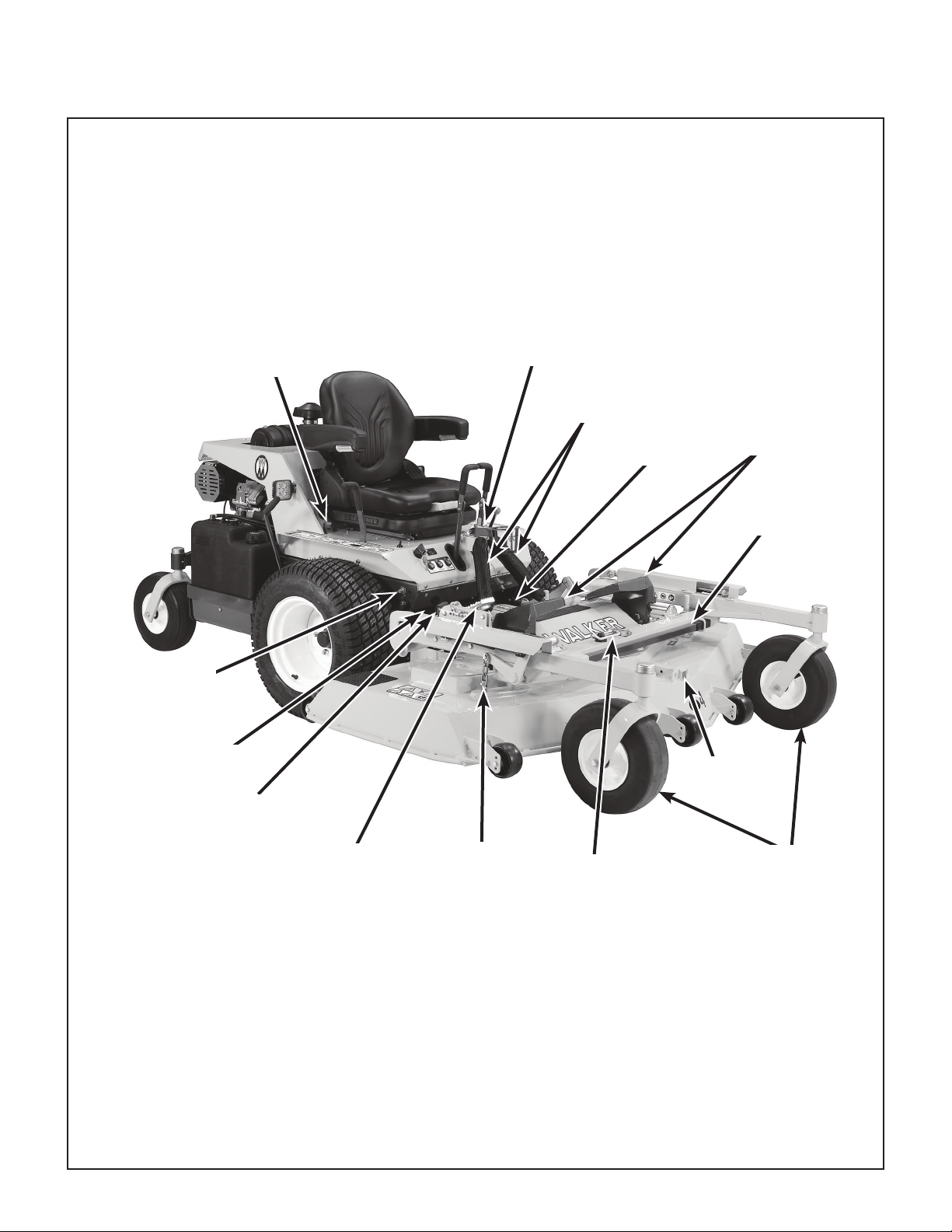
Component Identication ...................................6
Safety Instructions 9
Before Operating .................................................9
Operating........................................................... 11
Maintenance...................................................... 13
Safety, Control, And Instruction Decals ......... 14
Assembly Instructions 18
Setup Instructions.............................................18
Tire Installation (Tractor)...........................................18
Battery Service..........................................................18
Battery Charging ...................................................19
Battery Installation.................................................19
Mower Deck Assembly..............................................19
Deck Caster Wheels Installation ...........................19
Deck Discharge Deector
Shield Installation ..................................................20
PTO Shaft Guard Installation ................................20
Tilt-Up Roller Wheel Installation............................20
Mower Deck Installation on Tractor...........................20
Deck Installation....................................................20
Deck Leveling........................................................22
Measuring Deck Levelness ...........................22
Deck Leveling Procedure..............................23
Preoperating Checklist .....................................24
Operating Instructions 27
Control Identication, Location, and
Function ............................................................27
Ignition Switch...........................................................27
Engine Throttle..........................................................28
Body Latch................................................................28
Forward Speed Control (FSC) ..................................28
Steering Levers.........................................................28
Blade Clutch (PTO)...................................................28
Parking Brake ...........................................................29
Oil Pressure Warning Light/Horn ..............................30
Engine Service Light.................................................30
Over Temperature Warning Light/Horn .....................30
Transaxle Lockout Arms ...........................................31
Circuit Breaker ..........................................................31
Hourmeter.................................................................31
Roll-Over Protection System (ROPS, Optional)........32
Suspension Seat.......................................................33
Starting the Engine............................................36
Adjusting Ground Speed and Steering ...........36
Engaging the Blade Drive.................................38
Stopping the Machine .......................................39
Fuel Tank Selector Valve...................................40
Adjustable Foot Rests.......................................40
Adjusting Cutting Height ..................................40
Transport Position.....................................................41
Transaxle Lockout.............................................41
Recommendations for Mowing ........................42
Recommendations for Towing .........................44
Recommendations for Tilt-Up Deck
Operation/Transport..........................................44
Maintenance Instructions 45
Maintenance Schedule Chart .......................... 45
Important Tips for Care of the
Briggs & Stratton Engine..................................46
Fuel System..............................................................46
Starting/Stopping ......................................................46
Cooling System.........................................................46
Air Cleaner System...................................................46
Oil..............................................................................46
Lubrication.........................................................47
Engine Oil .................................................................47
Engine Break-In Oil ...............................................47
Checking Engine Crankcase Oil Level..................47
Changing Engine Crankcase Oil/Oil Filter.............48
Mower Deck Spindle Lubrication ..............................49
DR52, DS61 or DR64 Mower
Deck Lubrication .......................................................49

Table of Contents H37i
Check Transaxle Fluid Level.....................................49
Grease Fitting and Oil Point Lubrication ..................49
Transaxle Oil and Filter Change ...............................52
Cleaning .............................................................53
Engine Air Cleaner System.......................................53
Briggs & Stratton Air Cleaner ................................53
Engine Cooling System.............................................55
Cooling Air Intake Screen......................................55
Cylinder Head Cooling Fins...................................55
Grass Buildup in Mower Deck Housing ....................56
Transaxle Housing ....................................................58
Checking/Servicing ...........................................59
Security of Air Cleaner System .................................59
Battery.......................................................................59
Cleaning the Terminals..........................................59
Charging the Battery .............................................60
Tire Pressure ............................................................60
Wheel Nut Torque .....................................................60
Sharpen Mower Blades.............................................60
Drive Belts.................................................................61
Spark Plugs...............................................................61
Ignition Wires ............................................................61
Fuel Lines and Clamps .............................................62
Engine Starter ..........................................................62
Transmission Control Setting....................................62
Neutral-Park ..........................................................62
Straight Ground Tracking ......................................62
Blade Brake Action....................................................62
PTO U-Joints ...........................................................62
Safety Switch System ...............................................63
Forward Speed Control Friction Lock .......................63
Replacing/Repairing..........................................64
Drive Belts.................................................................64
Engine/PTO Belt....................................................65
Ground Drive Belt..................................................66
Deck Drive Belt......................................................67
Fuel Filter .................................................................68
Mower Blades ...........................................................68
Adjustments.......................................................70
Transmission Control ................................................70
Steering Lever Position Adjustment ......................70
Steering Handle Adjustment..................................70
Neutral Function Adjustment .................................71
Full Forward Speed Adjustment ............................72
Straight Tracking Adjustment.................................72
FSC Neutral Switch Adjustment ............................72
Forward Speed Control
Friction Adjustment................................................73
Blade Clutch (PTO)...................................................74
Clutch Engagement/Belt Tension ..........................74
Clutch Disengagement/Brake Action.....................75
Idler Pulley Maximum Travel Adjustment ..............75
Blade Brake Band Adjustment ..............................76

H37i General Information
1
General Information
HIGHLIGHTED INFORMATION
Walker Manufacturing recommends that any ser-
vice requiring special training or tools be performed
by an authorized Walker Mower dealer. There are
several general practices to be aware of in the
area of safety. Most accidents associated with the
operation or maintenance of a Walker Mower are
caused by disregarding basic safety precautions or
specic warnings. Such accidents, in most cases,
can be prevented by being aware of the dangers
present.
Information of special importance has been high-
lighted in bold type in this manual. Refer to Safety
Instructions on page 9 for the meanings of
DANGER, WARNING, CAUTION, IMPORTANT,
and NOTE.
GLOSSARY
There are many terms that are either unique to this
equipment or that are used as acronyms. The
following terms and their denitions will help while
using this manual:
●DECK is the mowing attachment mounted on
the front of the tractor which includes the
carrier frame, deck housing, blade spindles,
and cutter blades.
●ELECTRONIC CONTROL UNIT (ECU)
controls engine functions such as spark timing,
fuel/air ratio, etc.
●FORWARD SPEED CONTROL (FSC) controls
the maximum forward speed of the tractor;
functioning as a cruise control.
●GROUND DRIVE refers to the dual transaxles
which drive the main wheels.
●LEFT HAND (LH) refers to the left-hand side
of the tractor when the operator is seated
facing forward in the tractor seat.
●POWER TAKE-OFF (PTO) transmits engine
power to run the cutter blades.
●REAR DISCHARGE (RD) discharges mowed
material from the back of the mower deck.
●RIGHT HAND (RH) refers to the right-hand
side of the tractor when the operator is seated
facing forward in the tractor seat.
●ROLL-OVER PROTECTION SYSTEM
(ROPS) oers enhanced operator protection in
the event of a roll-over type accident.
●SIDE DISCHARGE (SD) discharges mowed
material from the right side of the mower deck.
●STEERING LEVERS steer the tractor by
con trolling the two transaxles.
●TRACTOR is the prime mover, including the
engine, drivetrain, operator seat, and controls
to operate the mower.
●TRANSAXLE transmits and controls power
from the ground drive belt to the main drive
wheel.
●TRANSAXLE LOCKOUT ARMS release the
transaxles to permit freewheeling the tractor.
IDENTIFYING NUMBER LOCATIONS
The tractor serial number plate is axed to the
tractor body just below the left rear corner of the
seat. The mower deck serial number plate is
axed alongside the angle iron framing on the LH
side of the LH mower blade drive. Model and
serial numbers are helpful when obtaining replace-
ment parts and maintenance assistance. For
ready reference, please record these numbers in
the space provided.
Tractor Model No. ______________________
Tractor Serial No. ______________________
Deck Serial No. ______________________
Engine Model No. ______________________
Engine Serial No. ______________________
Date of Purchase ______________________
Fill In By Purchaser

General Information H37i
2
Serial Number
Tractor Serial Number Location
Serial Number
Mower Deck Serial Number Location
ENGINE SERIAL NUMBER LOCATION
Refer to the engine manual that accompanies this
manual or photo below for the location of the
engine serial number.
Serial Number
Engine Serial Number Location
SERVICING OF ENGINE AND DRIVE-
TRAIN COMPONENTS
The detailed servicing and repair of the engine and
transaxles are not covered in this manual. Only
rou tine maintenance and general service instruc-
tions are provided. For the service of these com-
ponents during the limited warranty period, it is
important to nd a local, authorized servicing agent
of the com ponent manufacturer. Any unauthor-
ized work done on these components during the
warranty period may void the warranty. If you
have any di culty nding an authorized outlet or
obtaining warranty service, please contact our
Service Depart ment for assistance:
Walker Manufacturing Company
5925 E. Harmony Road
Fort Collins, CO 80528
1-970-221-5614
www.walker.com
Service manuals are available for each of these
components from their respective manufacturers
as follows:
Briggs & Stratton
Engines
Briggs & Stratton
800-233-3723
(24-hour hotline in
USA & Canada)
www.briggsandstratton.com
Transaxles Hydro-Gear
1411 South Hamilton St.
Sullivan, IL 61951
877-728-7410
www.hydro-gear.com

H37i Specications
3
SPECIFICATIONS
ENGINE
Manufacturer/Model Briggs & Stratton Vanguard, 2 Cyl. OHV, Gasoline (Air-Cooled),
Electronic Fuel Injection (EFI)
Displacement cu. in. (cc) 60.6 (993)
Max. Power HP (kW) 37.0 (28.3) @ 3600 RPM
Governed RPM 3600
Max. Torque lb·ft (N·m)54 (73.2) @ 3000 RPM
Idle RPM 1600
Spark Plug Type Champion® XC92YC
Spark Plug Gap in. (mm) .030 (0.76)
Crankcase Capacity qt (L) 2.4 (2.3)
Crankcase Lubricant Synthetic or API SF or Higher Grade Oil Only with 10W-30 Viscosity,
0º to 100º F (-18º to 38º C), or 5W-30 Viscosity Above 100º F (38º C),
or Below 40º F (4º C)
Oil Filter Briggs & Stratton P/N 842921
Cooling System Air-Cooled
Fuel Tank Capacity gal (L) 9.4 (35.6), Two Independent 4.7 Gallon Tanks with Selector Valve
Fuel Regular Grade Unleaded Gasoline
(87 Octane Minimum, 10% Ethanol Maximum)
Air Cleaner Engine Mounted (Briggs & Stratton)
(Briggs & Stratton P/N 841497 Primary/P/N 821136 Safety Filter)
ELECTRICAL SYSTEM
Battery 12 Volt, 350 CCA (Interstate SP-40)
Charging System Flywheel Alternator
Charging Output 50 Amp DC (Regulated)
System Polarity Negative Ground
Ignition Electronic Capacitive Discharge
Starter 12 Volt Electric Ring-Gear Type, Solenoid Shift
Interlock Switches Ignition Lockout by Seat Switch, Transmission Neutral,
Blade Clutch, and Parking Brake
Circuit Breakers Manual Reset (20A)
Auto Reset (30A)
TRANSMISSION
Manufacturer/Model Dual, Independent Hydro-Gear® ZT3400 Integrated Transaxles
Steering Hand Lever Control / Individual Wheel
Forward Speed Control Precision Friction Lock Lever, Cruise Control, with
Neutral-Park Position
Service Brake Dynamic Braking through Transaxles
Parking Brake Internal Mechanical Cog Lock for each Transaxle
(Single Lever Control)

Specications H37i
4
TRANSMISSION (CONTINUED)
Neutral Transmission Release by Manual Dump Valve
Final Drive Direct Drive Axle from Transaxle
Transmission Fluid
Factory Service 20W-50 Multi-Viscosity Motor Oil (Minimum SL Grade Oil)
Transmission Oil Capacity oz (L) 77 (2.3)
Transmission Cooling Cooling Fan Mounted on Drive Pulley
Oil Filter Hydro-Gear® P/N 52114 (Walker P/N 2026-6)
Ground Travel Speed
Forward MPH (km/h)
Reverse MPH (km/h)
0-10 (0-16) Innitely Variable
0-5 (0-8) Innitely Variable
BLADE DRIVE
PTO Shaft Quick Disconnect Sliding Spline Shaft with Two (2) High-Speed
U-Joints
Blade Drive Clutch and Brake Manual Belt Tightener Clutch and Band Brake
[Stops Blades within Five (5) Seconds of Disengagement]
TIRE SIZE
Deck Caster Wheel 13 x 4.50-6 (Pneumatic 6-Ply)
Drive 22 x 10.50-12 (4-Ply Low-Prole)
Tailwheel 13 x 4.50-6 (Pneumatic 6-Ply)
TIRE PRESSURE PSI (KPA)
Deck Caster Wheel 20 (137)
Drive 15 (103)
Tailwheel 20 (137)
DRIVE BELTS
Engine PTO Walker P/N 2230 (Set of 3)
Ground Drive Walker P/N 2248-1
SEAT Full Spring Suspension with Dampening and Adjustments for Back
Angle, Lumbar Support, and Operator Weight. Standard with Ad-
justable/Retractable Armrests.
FRAME/BODY CONSTRUCTION
Frame All Welded Unitized Steel Chassis
Body 14 Gauge Steel
Deck 11 Gauge Steel
TOWING
Towing Capacity lb (kg) 250 (113) if equipped with a factory installed or factory authorized
tow hitch

H37i Specications
5
DIMENSIONS (TRACTOR AND MOWER)
Length in. (cm)
Tractor Only 69 (175)
Tractor Wheel Base 45 (115)
Tractor with Tilted Deck
(Approximate)
87.75 (223)
Tractor with 64" Rear Discharge
Deck (DR64-3)
107.75 (274)
Width in. (cm)
Tractor Only (Outside Tire) 46.5 (118)
Tractor with 64" Rear Discharge
Deck (DR64-3)
66 (168)
Tread Width 36.5 (93)
Height in. (cm)
Tractor 46.5 (118)
With ROPS (Optional) 66.25 (168)
With ROPS (Optional) Lowered 51.25 (130)
Weight lb (kg)
Tractor Only 778 (353)
Tractor with 64" Rear Discharge
Deck (DR64-3)
1215 (551)
DECK DR52 DR64 DS61
Type Belt-Driven,
Rear Discharge
Belt-Driven,
Rear Discharge
Belt-Driven,
Side Discharge
Cutting Width in. (cm) 52 (132) 64 (163) 61 (155)
Cutting Height in. (cm) 1.5 to 5 (3.8 to 12.7)
Height Adjustment in. (cm) 1/4 (1) Increments, 15 Positions
Blade Length in. (cm) 18.4 (47) 22.2 (56) 20.5 (52)
Number of Blades 3
Direction of Rotation
(Viewed from top of deck)
Clockwise
Deck Suspension Torsion-Flex Frame with Caster Wheels and Counterweight Springs
Maximum Blade RPM 3840 3200 3330
Maximum Blade Tip Speed
ft/min (m/min)
18500 (5640) 18500 (5640) 17870 (5460)
NOTE: The manufacturer reserves the right to make changes in specications shown herein at any time
without notice or obligation. The specications listed are for a standard conguration tractor, and may
change with the addition of optional equipment.

Component Identication H37i
6
COMPONENT IDENTIFICATION
NOTE: Operator Controls are identied in the sec-
tion Operating Instructions on page 27.
Front View and Right Side View
Body Tilt-Up
Latch
Deck Height
Lift Chain
Deck
Tilt-Up Bar
Deck Support Arm
(Not Visible)
Adjustable
Footrests
Forward Speed
Control (FSC)
Friction
Adjustment
Deck Lift Foot Pedal
(Raises Deck)
Cutting Height Release Lever
(Cutting Height Adjustment)
Deck Support Arm
Tilt-Up Latch
Deck Tilt-Up
Socket
Tilt-Up
Hook
Deck
Caster Wheels
Counterweight Springs and
Protective Covers

H37i ComponentIdentication
7
Rear View and Left Side View
Adjustable
Footrest
Left Hand
Drive Wheel
Tail Wheel
Fuel Pickup
Line
Fuel Tank
and Cap
Cylinder Head Cooling
Fins
Muer
(Not Visible)
Fuel Gauge Oil Fill Dipstick Engine Air
Cleaner
Spread Axle
(Tail Wheel)
Tailpipe
Muer Heat
Shield
Body Lift
Handle

Component Identication H37i
8
Top View (Body Raised)
Muer Heat
Shield
Air Intake
Cover
RH Transmission
Control Rod
Steering Lever
Spring / Dampeners
Transaxle Oil
Expansion
Reservoir
LH Transaxle
PTO Clutch
Lever
LH Transmission
Control Rod
Air Cleaner
Cover
Battery
Fuel Gauge
Roll Over Valve
Air Cleaner
Oxygen
Sensor
Oil Filter
(Not Visible)
Electronic Control
Unit (ECU)
(Under Cover)
Oil Fill
(Not Visible)
Parking Brake
Safety Switch
Dipstick
Fuel Tank Cap
Fuel Tank
Fuel Tank
Selector Valve
EVAP Line
Fuel Filter
Fuel Pickup Line
Fuel Pump
(Low Pressure)
RH Transaxle
Clutch
Linkage
RH Transaxle
Lockout Arm
Parking Brake
Linkage
Parking Brake
Lever
LH Transaxle
Lockout Arm

H37i Safety Instructions
9
Safety Instructions
Pay particular attention to any information labeled
DANGER, WARNING, CAUTION, IMPORTANT,
and NOTE in this manual.
When you see the Safety Alert Symbol ( ),
read, understand, and follow the instructions. Fail-
ure to comply with safety instructions may result in
personal injury.
The seriousness or degree of importance of each
type of information is dened as follows:
DANGER
An IMMEDIATE hazard that WILL result in
severe personal injury or DEATH, if warn-
ing is ignored and proper safety precau-
tions are not taken.
WARNING
A POTENTIAL hazard that COULD result in
severe personal injury or DEATH, if warn-
ing is ignored and proper safety precau-
tions are not taken.
CAUTION
Possible hazards or unsafe practices that
MAY result in MODERATE personal injury
or property damage, or machine damage, if
warning is ignored and proper safety pre-
cautions are not taken.
IMPORTANT: Identies mechanical information
demanding special attention, since it deals with the
possibility of damaging a part or parts of the
machine.
NOTE: Identies information worthy of special
attention.
Walker Manufacturing cannot predict every poten-
tially dangerous situation. Therefore, items labeled
as such in this manual do not cover all conceivable
situations. Any person using procedures, tools, or
control techniques not recommended by Walker
Manufacturing must take full responsibility for
safety.
The Walker Rider Lawnmower has been designed
with many safety features to protect the operator
from personal harm or injury. However, it is neces-
sary for the operator to use safe operating proce-
dures at all times. Failure to follow safety
instructions contained in this manual may
result in personal injury or damage to equip-
ment or property.
If you have any questions concerning setup, oper-
ation, maintenance, or safety, please contact your
authorized Walker Mower Dealer or call Walker
Manufacturing Company at (970) 221-5614.
BEFORE OPERATING
1. Read and understand the contents of this
Operator’s Manual before starting and
operating the machine. Become thoroughly
familiar with all machine controls and how to
stop the machine and disengage the controls
quickly. Replacement Operator’s Manuals are
available by sending the Model and Serial
Number to:
Walker Manufacturing Company
5925 East Harmony Road
Fort Collins, CO 80528
2. Never allow children to operate rider mow-
er. Do not allow adults to operate without
proper instruction.
3. Clear the area to be mowed of any foreign
objects which may be picked up and thrown
by cutter blades. Pick up all sticks, stones,
wire, and any other debris.
4. Keep everyone, especially children and pets, a
safe distance away from the area being
mowed. Do not mow with bystanders in the
area.
5. Do not operate the machine barefoot or wear-
ing sandals, sneakers, tennis shoes, or similar
light weight footwear. Wear substantial pro-
tective footwear.

Safety Instructions H37i
10
6. Do not wear loose tting clothing that could
get caught in moving parts. Do not operate
this machine while wearing shorts; always
wear adequate protective clothing, including
long pants. Wearing safety glasses, safety
shoes, and a helmet is advisable and required
by some local ordinances and insurance regu-
lations.
7. Prolonged exposure to loud noise can cause
impairment or loss of hearing. Operator hear-
ing protection is recommended. Wear a
suitable hearing protective device, such as
ear mus or earplugs.
8. Keep all protective shields and safety de-
vices in place. If a protective shield, safety
device, or decal is damaged, unusable, or
miss ing, repair or replace it before operating
the machine.
9. Be sure interlock switches are functioning
correctly, so the engine cannot be started
unless the Forward Speed Control lever is in
the NEUTRAL-PARK position, the PTO clutch
is in the DISENGAGED position, and the Park-
ing Brake is in the ENGAGED position. Also,
the engine should stop if the operator lifts o
the seat with any one or more of these con-
trols in the operating position: (1) Forward
Speed Control (FSC) out of NEUTRAL-PARK,
(2) PTO Clutch ENGAGED, or (3) Parking
Brake DISENGAGED.
NOTE: There is a 1/2 second time delay
function on the seat switch to avoid engine
power interruption when driving over bumps.
10. Handle gasoline with care. Gasoline is
highly ammable and its vapors are explosive:
a. Use an approved fuel container.
b. Never add fuel to a running engine or hot
engine (allow hot engine to cool several
minutes).
c. Keep matches, cigarettes, cigars, pipes,
open ames, or sparks away from the fuel
tanks and fuel container.
d. Always ll the fuel tank(s) outdoors using
care. Fill to about one inch from the top of
the tank. Use a funnel or spout to prevent
spilling.
e. Replace the machine fuel cap(s) and con-
tainer cap securely and clean up any
spilled fuel before starting the engine.
11. Never attempt to make any adjustments
while the engine is running, except where
spe cically instructed to do so.
12. The electrical system battery contains sulfuric
acid. Avoid any contact with skin, eyes, and
clothing. Keep the battery and acid out of
reach of children.
WARNING
This product can expose you to chemicals
including Di-(2-ethylhexyl) phthalate which
is known to the State of California to cause
cancer, and Di-(2-ethylhexyl) phthalate,
which is known to the State of California
to cause birth defects or other reproduc-
tive harm. For more information go to
www.P65Warnings.ca.gov.

H37i Safety Instructions
11
OPERATING
WARNING
If Equipped With ROPS:
●Always keep the ROPS roll bar in the
upright and locked position when oper-
ating.
●Always use the seat belt when the roll
bar is upright.
●Only lower the roll bar when absolutely
necessary for overhead clearance.
●Never use the seat belt when the roll
bar is lowered.
1. Operate the mower only in daylight or in
good articial light with good visibility of the
area being mowed.
2. Sit on the seat when starting the engine and
operating the machine. Keep feet on the deck
footrests at all times when the tractor is mov-
ing and/or mower blades are operating. Nev-
er operate the tractor without a deck or
implement installed.
3. For a beginning operator, learn to steer (ma-
neuver) the tractor with a slow engine
speed before attempting any mowing oper-
ation. Be aware that, with the front mounted
mower conguration, the back of the tractor
swings to the outside during turns.
DANGER
Do not mow around overhanging tree
branches or bushes at the same height as
the operator’s torso and head where inad-
vertent contact may cause injury.
4. Remember, for an emergency stop, the for-
ward motion of the tractor can always be
stopped by pulling the Forward Speed Control
(FSC) into the NEUTRAL-PARK position.
5. In case the transmission drive belt breaks
during operation, and if the machine is on a
slope, the machine will freewheel down the
slope. To maintain control, immediately (1)
Release the steering levers and simultane-
ously (2) Move the FSC to the NEUTRAL-
PARK position. When the machine is stopped
or moving slowly, engage the parking brake.
NOTE: The emergency stop procedure is
exactly the same procedure as used to nor-
mally stop and park this machine.
6. Disengage the blade clutch, put the FSC in the
NEUTRAL-PARK position, and engage the
Parking Brake before starting the engine (an
ignition interlock switch normally prevents
starting of the machine if these controls are in
the OPERATING position).
7. Do not operate machine if the operator
presence safety switch system is not work-
ing. Verify proper operation by having the
operator lift o the seat with the engine run-
ning and moving three controls, one at a time;
(1) Move the FSC lever out of the NEUTRAL-
PARK position, (2) Engage the PTO Clutch,
and (3) Disengage the Parking Brake. Moving
any of these controls should stop the engine
after a 1/2 second delay.
8. Do not run the engine in a conned area
without adequate ventilation. Exhaust
fumes are hazardous and can be deadly.
9. Do not carry passengers - maximum seating
capacity is one (1) person.
10. Watch for holes, rocks, and roots in the terrain
and for other hidden hazards. When mowing
tall grass, mow higher than desired to expose
any hidden obstacles. Then, clean the area
and mow to the desired height.
11. Avoid sudden starts or stops. Before back-
ing the machine up, look to the rear to be sure
no one is behind the machine. Watch carefully
for trac when crossing or working near road-
ways.

Safety Instructions H37i
12
12. When moving forward, do not suddenly put
the tractor in reverse by rapidly pulling on the
steering levers, especially when going down-
hill, as this can lift the tractor tail wheel o the
ground and set up a bucking motion due to
operator overcontrol. If bucking does occur,
immediately stop the bucking action by pulling
the Forward Speed Control (FSC) lever into
the NEUTRAL-PARK position.
13. Disengage the blade drive when transporting
the machine across drives, sidewalks, etc.
Never raise the mower deck while blades
are rotating.
DANGER
Do not mow or drive the tractor within 5 feet
(1.5 meters) of an embankment or retaining
wall with drop o.
14. The maximum recommended slope operat-
ing angle is 15 degrees or 27% grade.
When operating the machine on a slope, re-
duce speed and use caution to start, stop, and
maneuver. To prevent tipping or loss of control
of the machine, avoid sharp turns or sudden
changes in direction. Do not operate the
machine on a slope greater than 15 de-
grees.
15. Never adjust cutting height with the engine
running. Before adjusting cutting height or
servicing, disengage the blade clutch (PTO),
engage parking brake, stop the engine, and
remove the ignition key. Wait for all movement
to stop before getting o the seat.
NOTE: The blade/PTO brake should normally
stop drive line rotation within ve (5) seconds
of dis engaging the PTO clutch.
16. For side discharge mower decks, do not op-
erate with the grass deector shield re-
moved. Keep the deector in the low est
possible position.
17. When using the tilt-up deck, observe the
following:
a. Do not move tractor with deck in tilt-up
position.
b. Never tilt body forward with deck in tilt-up
position.
18. In case of a clogged or plugged mower
deck:
a. Disengage the blade clutch (PTO), engage
the parking brake, and turn the engine o
before leaving the seat.
b. LOOK to make sure blade drive shaft
move ment has stopped before trying to
unclog the system.
c. Disconnect the spark plug wires.
d. Never place hands under the deck - use a
stick or similar tool to remove clogged
ma terial.
19. If the cutting blades strike a solid object or the
machine begins to vibrate abnormally, imme-
diately disengage the blade clutch (PTO),
engage the parking brake, stop the engine,
and wait for all moving parts to stop. To
prevent accidental starting, disconnect the
spark plug wires. Thoroughly inspect the
mower and repair any damage before restart-
ing the engine and operating the mower.
Make sure cutter blades are in good condition
and blade nuts are torqued to 60 lb·ft (81 N·m)
for gear-driven decks, and blade bolts torqued
to 70 lb·ft (95 N·m) for belt-driven decks.
20. Do not touch the engine or muer while
the engine is running or immediately after
stop ping the engine. These areas may be hot
enough to cause serious burns.
21. Do not stop or park in or near dry grasses
or bushes when operating the mower. The
heat from the engine or muer could ignite the
dry material.
22. When leaving the machine unattended, disen-
gage the blade clutch (PTO), engage the
parking brake, stop the engine, and remove
the key.
23. When equipped with a factory installed hitch or
factory authorized hitch kit, do not exceed
recommended tow capacities. Do not tow
with the PTO clutch or mower blades en-
gaged, and do not allow people to ride in or
on towed trailers.
24. Use caution when towing on slopes, rough
terrain or when conditions limit traction. Do not
tow on slopes greater than 5 degrees (9%).

H37i Safety Instructions
13
MAINTENANCE
1. To prevent accidental starting of the engine
when servicing or adjusting the machine,
remove the key from the ignition switch and
disconnect the spark plug wires.
2. To reduce re hazards, keep the engine free
of grass, leaves, excessive grease, and dirt.
3. Keep all nuts, bolts, and screws tight to ensure
the machine is in a safe, working condition.
Check the blade mounting bolts frequently,
making sure they are tight.
4. Perform only maintenance instructions
described in this manual. Unauthorized
maintenance operations or machine modica-
tions may result in unsafe operating condi-
tions.
5. If the engine must be running to perform a
main tenance adjustment, keep hands, feet,
and clothing away from moving parts. Do not
wear jewelry or loose clothing.
6. Always use the proper engine service man-
ual when working on the engine. Unauthor-
ized maintenance operations or modications
to the engine may result in unsafe operating
conditions.
7. Altering the equipment or engine in any man-
ner which adversely aects its operation,
perfor mance, durability, or use will VOID the
warranty and may cause hazardous condi-
tions.
8. Never attempt to disconnect any safety devic-
es or defeat the purpose of these safety de-
vices.
9. Do not change the engine governor settings or
overspeed the engine. The governor has
been factory-set for maximum-safe engine
operating speed.
10. Use genuine factory replacement parts.
Sub stitute parts may result in product malfunc-
tion and possible injury to the operator and/or
others.
11. Use care when charging the battery or
per forming maintenance on the battery and
electrical system:
a. Make sure the battery charger is un-
plugged before connecting or disconnect-
ing cables to the battery.
b. Charge the battery in a well-ventilated
space, so gases produced while charging
can dissipate.
c. Keep sparks, ames, and smoking materi-
als away from the battery at all times. To
avoid sparks, use care when removing
bat tery cables from posts.
d. Disconnect both battery cables before
unplugging any wiring connectors or mak-
ing repairs on the electrical system.
12. Do not attempt to service the engine fuel injec-
tion system, which contains high pressure fuel
and may cause injury if mishandled. For ser-
vice of the pressurized fuel system, including
the fuel pump, fuel lines, and fuel injectors,
contact your Walker dealer or authorized
Briggs & Stratton service dealer.
IMPORTANT: Keep all applicable manuals
immediately accessible to anyone who may
operate or service this machine.

Safety Instructions H37i
14
SAFETY, CONTROL, AND INSTRUCTION DECALS
Safety, Control, and Instruction Decals are installed on the machine;
if any are missing, illegible, or damaged, a replacement should be ordered and installed before
putting the machine into operation. The Decal Part Number is listed below and in the Parts Manual.
Location: Deck Carrier Frame
Part Number: 8600-14
8600-14
Warning – do not operate the machine with the
deck tilted up.
Location: Chassis Member Behind Transaxles
Part Number: 9804-1
9804-1
Neutral Lock
● Lift and move back to engage step to unlock
transmission and allow machine to freewheel.
Location: Engine Shroud, LH Side
Part Number: 8600-12
8600-12
Warning – carbon monoxide (CO) poisoning hazard.
● CO emitted by a running engine can be deadly.
● Do not operate indoors or in other enclosed
areas.
Grease PTO shaft joints every 8 hours.
Location: PTO Guard on Deck
Part Number: 8746-2
Location: Each End of Mower Deck
Part Number: 8600-28
1. Warning – thrown object hazard.
● Keep bystanders away from the machine
when operating.
● Clear lawn of debris before operating.
● Keep any discharge deector in place and
in the lowest position.
2. Warning – rotating mower blades are a cutting/
dismemberment hazard to hands and feet.
● Keep all body parts away from rotating
mower blades.
● Do not step on end of deck.
8746-2
8600-28
1.
2.
Fuel tank selector valve.
Location: Adjacent to Left Fuel Tank
Part Number: 2010-16
Location: Underside of Rear Body, Behind Seat
Part Number: 5855
Location: Deck Carrier Frame
Part Number: 8600-15
Warning – lock deck tilt-up hinge before operating
the machine.
Location: Rear Body Near Muer
Part Number: 8600-5
8600-5
Warning – hot surface, do not touch.

H37i Safety Instructions
15
SAFETY, CONTROL, AND INSTRUCTION DECALS
Safety, Control, and Instruction Decals are installed on the machine;
if any are missing, illegible, or damaged, a replacement should be ordered and installed before
putting the machine into operation. The Decal Part Number is listed below and in the Parts Manual.
Location: Deck Discharge Shield (DS61)
Part Number: 5848-3
Warning – thrown object hazard.
● Always keep the discharge shield in the lowest
position when operating.
● Do not remove the discharge shield.
Location: Top of Deck Housing
Part Number: 8653-1
Warning – secure deck with straps and engage
parking brake before transporting or trailering with
deck tilted up.
Location: Deck Height Adjuster
Part Number: 2748-2
Move pin to desired height of cut.
Location: Flex Coupler Guard in Front of Engine
Part Number: 8600-2
Warning – entanglement and cutting/
dismemberment hazards.
● Keep away from rotating shafts, belts, and
other components.
8600-2
Location: Deck Housing Under Footrest
Part Number: 2749-7
DR64 deck drive belt routing.
DR64 BELT P/N 2731-5
BELT T WIST
2749-7
Location: Deck Housing Under Footrest
Part Number: 2749-5
DR52 deck drive belt routing.
BELT ROUTING
BELT TWIST
BELT TWIST
2749-5
Location: Deck Housing Under Footrest
Part Number: 2749-8
DS61 deck drive belt routing.
2749-8
BELT TWIST
BELT TWIST
BELT ROUTING
DS61 BELT P/N 2731-6

Safety Instructions H37i
16
SAFETY, CONTROL, AND INSTRUCTION DECALS
Safety, Control, and Instruction Decals are installed on the machine;
if any are missing, illegible, or damaged, a replacement should be ordered and installed before
putting the machine into operation. The Decal Part Number is listed below and in the Parts Manual.
Location: Right Fender
Part Number: 2802-4
1. Warning – do not operate the machine without
a deck or other implement attached.
2. Forward Speed Control
● Move lever forward to increase speed;
back to stop.
3. Body Tilt Latch
● Raise lever to release.
● Lift at back of body to raise.
4. Warning – do not engage PTO clutch with
PTO shaft disconnected.
5. PTO Clutch Lever
● Move lever forward to engage PTO clutch;
back to disengage.
1. Warning – roll-over/crushing hazard.
● Do not operate the machine on steep
slopes or near drop-os.
● Avoid quick and/or sharp turns when
operating on slopes.
2. During normal operation always keep the
ROPS locked fully upright and use the seat
belt.
3. Never use the seat belt if the ROPS is not
locked fully upright.
4. Do not operate the machine on slopes if the
ROPS is not locked fully upright.
5. Do not remove the ROPS.
Location: ROPS Roll Bar (If Equipped)
Part Number: 5685-3
2.
3.
1.
4.
5.
5685-3
2.
3.
4.
5.
1.
Other manuals for H37i
1
Table of contents
Other Walker Lawn Mower manuals

Walker
Walker H27i User manual

Walker
Walker B27i User manual

Walker
Walker C23i User manual

Walker
Walker MC (16 HP) Setup guide

Walker
Walker B19 User manual

Walker
Walker H27i User manual

Walker
Walker R21 User manual

Walker
Walker MT, MTL, MTEFI, MTLEFI User manual

Walker
Walker MC (20 HP) User manual

Walker
Walker MC36-54 Setup guide

Walker
Walker T25i User manual

Walker
Walker D21d User manual

Walker
Walker D21d User manual

Walker
Walker M36-42 User manual

Walker
Walker MS (13 HP) User manual

Walker
Walker H24d User manual

Walker
Walker MBSSD (27 HP) User manual

Walker
Walker MDD User manual

Walker
Walker MBSY User manual

Walker
Walker C19 Setup guide