WALPOL WDV-A 355 EC User manual

Roof fan TYPE WDV
Assembly and operating instructions
Version 6.1
B05

2
1.
General information 3
1.1. Note symbols 3
2. Important safety instructions 3
2.1. Personal 3
2.2. Personal protective equipment 4
2.3. The 5 safety rules for working in and on electrical installations 4
3. Warranty 4
4. Delivery, transport, storage 4
5. Description 5
5.1. Roof fans EC motor series WDV-A 5
5.2. Roof fans with AC motor WDV-A and WDV-K series 6
5.3. Description roof fans 6
5.4. Fan and motor data 7
5.5. Intended use 7
6. Nameplate and type key 7
7. Accessories 7
8. Installation 7
9. Installation of the ventilation system 8
9.1. Assembly/disassembly of impeller - internal rotor motor WDV-A series 9
10. Electrical connection 11
10.1. Motor protection 11
10.2. Fans with variable speed 11
11. Commissioning 12
12. Operation 13
13. Troubleshooting/Maintenance/Repair 13
13.1. Safety instructions 13
13.2. Troubleshooting 13
13.3. Maintenance 15
13.4. Spare parts 15
14. Cleaning 15
15. Disassembly / removal 16
16. Disposal 16
17. EU Declaration of Conformity - Roof Fans 16
18. Commissioning protocol 16
Content

3
1. General information
1.1. Note symbols
Danger
Immediate danger
Failure to observe the warning will result directly in
death or serious injury.
Caution
Hazard with low risk
Failure to observe the warning may result in
moderate injury.
Warning
Potential danger
Failure to observe the warning may result in death or
serious injury.
Important
Danger with risk of property damage
Failure to observe the warning may result in
damage to property.
Note
Useful information and instructions
2. Important safety instructions
Planners, plant constructors and operators are responsible for proper installation and operation in accordance with the
intended use.
• Read the operating instructions completely and carefully.
• Operating instructions and other applicable documents, such as electrical connection diagrams or operating
instructions for the motor, must be kept with the fan. They must be available on site at all times.
• Local and national laws and regulations must be observed and complied with.
• Consider the plant-relevant conditions and requirements of the plant manufacturer or plant builder.
• Safety devices must not be dismantled, bypassed or rendered inoperative.
• The fan may only be used when in perfect condition.
• The generally prescribed electrical and mechanical protective devices must be provided.
• During installation, electrical connection, commissioning, troubleshooting and maintenance, secure the installation
site and the premises against access by unauthorized persons.
• Safety devices must not be dismantled, bypassed or rendered inoperative.
• Ensure that all warning labels on the fan are complete and legible.
• This appliance is not intended for use by persons (including children) with reduced physical or mental capabilities,
or lack of experience and knowledge, unless they have been given supervision or instruction concerning use of the
appliance by a person responsible for their safety.
• Children are not allowed to play with the device.
2.1. Personal
The fan may only be operated by qualified, instructed and trained personnel. These persons must know the relevant safety
regulations in order to recognize and avoid possible dangers. The individual actions and qualifications can be found in Table
1 Qualifications, page 3.

4
Table 1 Qualification
Actions Qualification
Storage, operation, transport, cleaning,
disposal
Trained personnel (see following notes)
Electrical connection, commissioning,
electrical isolation
Qualified electrician or persons with
corresponding qualification
Installation, disassembly Assembly specialist or persons with
corresponding qualification
Maintenance Qualified electrician
or persons with
corresponding
qualification
Assembly specialist
or persons with
corresponding
qualification
Repair Qualified electrician
or persons with
corresponding
qualification
Assembly specialist
or persons with
corresponding
qualification
Note
The operator must ensure that the personnel have been instructed in the
operation and have understood the operating instructions. If you are unsure,
please contact Walpol or our representatives.
2.2. Personal protective equipment
Wear protective equipment during any work in the vicinity of the fan.
• Protective clothing
• Safety shoes
• Protective gloves
• Safety helmet
• Safety goggles
• Hearing protection
2.3. The 5 safety rules for working in and on electrical installations
. Disconnecting (all-pole
disconnection of an electrical
system from live parts)
. Secure against restarting
. Determine freedom from
voltage
. Grounding and shorting
. Cover or fence off adjacent live
parts
3. Warranty
For warranty claims to be valid, the products must be properly connected and operated and used in accordance with the
data sheets. Prerequisites are also a fully completed maintenance plan and commissioning report, which are requested by
Walpol in the event of a warranty claim. The commissioning report is part of this document, the maintenance plan is to be
prepared by the operator, see chapter 13.3 Maintenance
4. Delivery, transport, storage
Safety instructions
Warning: Danger due to rotating fan blades
• Prevent unauthorized persons from entering by security personnel or an access guard.

5
Warning: Suspended loads
• During any work in the vicinity of the fan, the protective equipment must be worn, see 2.2 Personal protective
equipment,
• Never step under suspended load.
• Ensure that no one is under a suspended load.
Delivery
Every fan leaves our factory in perfect electrical and mechanical condition. It is recommended that the fan be transported to
the installation site in its original packaging.
Check delivery
• Check the packaging for transport damage. Any damage must be noted in the cargo manifest.
• Check if the delivery is complete.
Unpacking
Warning
When removing the transport packaging, there is a risk of damage from sharp edges, nails, staples, splinters, etc.
• Carefully unpack the fan.
• Check the fan for obvious transport damage.
• Do not remove the packaging until just before assembly.
• During any work in the vicinity of the fan, the protective equipment must be worn, see . Personal protective
equipment
Transportation
Safety instructions
• The fan must never be carried by the connecting cable, plenum box, impeller, guard grille, inlet nozzle or silencer.
• In the case of open transport, ensure that no water can penetrate the motor or other sensitive components.
• It is recommended that the fan be transported to the installation site in its original packaging.
Caution: Careless loading or unloading may cause damage to the fan.
• Carry out the loading or unloading carefully.
• Use lifting equipment designed for the load.
• Observe the transport arrows on the packaging.
• The packaging serves exclusively as transport protection and must not be used for lifting.
Storage
• Store the fan in its original packaging in a dry, dust-free place protected from the weather.
• Avoid exposure to extreme heat or cold.
Important
Danger due to loss of function of the motor bearing
• Avoid too long storage periods (recommendation: max. year).
• Before installation, check that the motor bearing is working correctly.
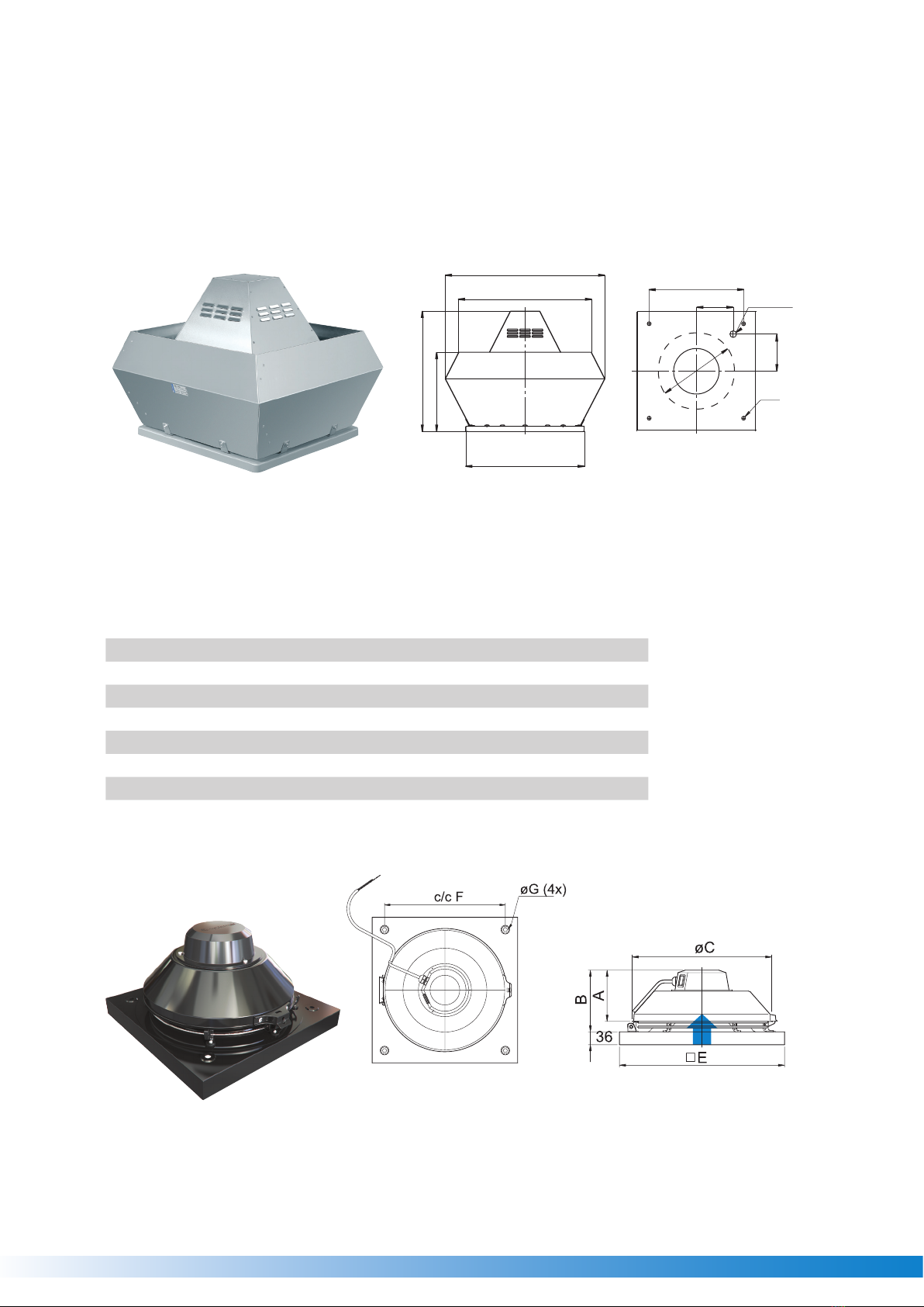
5. Description
5.1. Roof fans EC motor series WDV-A
The fans are driven by EC motors. The fans must be controlled with a potentiometer (0-10V). All motors are suitable for
50/60 Hz. The input voltage for single-phase devices is in the range of 200 and 277 V; for three-phase devices, the input
voltage is 380 and 480 V.
The maximum temperature of the pumped medium is +120°C.
Note
When installing EC motors, it must be ensured that the residual current circuit breaker of type
class: B or B+ are present in the circuit.

6
5.2. Roof fans with AC motor WDV-A and WDV-K series
Speed control options:
• 400V IE2/3 motors with frequency inverter with built-in sine filter control
• control 230V motors with transformer speed controller
The maximum fluid temperature is +120°C for series WDV-A
The maximum fluid temperature is +60°C for series WDV-K
5.3. Description roof fans
A
B
E
D
C
F
G
I
ø J(4x)
ø H
M20x1,5
Table dimensions roof fans TYPE A
Dimen-
sions
(in mm)
WDV-A
355 EC
WDV-A
400 EC
WDV-A
450
WDV-A
500
WDV-A
560
WDV-A
630
A 720 720 900 900 1150 1150
B 618 618 730 730 955 955
C 595 595 665 665 939 939
D 390 390 465 465 560 560
E 600 600 675 675 900 900
F 450 450 535 535 750 750
G 200 200 237 237 293 293
H 438 438 438 438 605 605
I 200 200 237 237 293 293

7
Table dimensions roof fans TYPE K
Dimensions
(in mm)
WDV-K
315
A 160
B 206
ØC 404
E 521
c/cF 450
ØG 11
5.4. Fan and motor data
• Max. Temperature of transported air, Max. Ambient temperature, Sound pressure level -> See general catalog,
available on our website.
• Voltage, amperage, protection class, weight -> See nameplate
• The motor data can be found on the motor nameplate or in the motor manufacturer's technical documentation.
5.5. Intended use
Roof ventilators type WDV-A, WDV-K
• The fans are designed for installation in ventilation systems.
• The fan is suitable for the transport of clean air.
• The maximum permissible operating data on the nameplate apply to an air density of 1.2 kg/m³ (NN) and a maximum
humidity of 80%.
•
Roof ventilators type WDV-K
• Roof fan with horizontal air outlet (discharge) Motor in air flow
• Not suitable for commercial kitchens, which must be executed according to VDI 2052.
All types:
Improper use is mainly when the fan is used in a way other than described. The following examples are contrary to regula-
tions and dangerous:
• Conveying explosive and flamma-
ble media
• Conveying aggressive media
• Operation in explosive environ-
ment
• Operation without duct system
or protective grille
• Operation with closed air
connections
• Conveying extremely polluted
air without pre-filtering
Note
We generally recommend pre-filtering the supply air before the fan
For example with a filter box or an activated carbon module, see WALPOL product range
6. Nameplate and type key
Each fan has a nameplate
Please compare the fan type/data with the version you ordered to avoid misunderstandings or wrong deliveries.
7. Accessories
We recommend original accessories from the company Walpol. For information contact the company Walpol

8
8. Installation
Safety instructions
Warning: Risk of impact from falling fan or fan parts.
• Before installation, check the surface for load-bearing capacity.
• Consider all static and dynamic loads when selecting lifting equipment and fasteners.
General safety instructions
• Installation may only be carried out by appropriately qualified persons, for details, see Table 1 Qualification, page 2.
• Move the impeller of the fan by hand before installing it to check its freewheeling.
• Provide contact protection, suction protection and safety distances according to DIN EN ISO13857 and DIN 24167-1.
• Prevent foreign particles from being sucked in.
• To prevent vibration transmission to the duct system, we recommend using the flexible connectors from our
accessories, see chapter Accessories.
Requirements
• Make sure that the fan and all its components are undamaged.
• Make sure that there is sufficient space for mounting the fan.
• When mounting the device, protect it from dust and moisture.
• Make sure that the specifications on the type plate (fan and motor) correspond to the operating conditions.
• Mount the fans so that there is sufficient access for troubleshooting, maintenance and repair.
9. Installation of the ventilation system
Important
Leaky roof due to incorrect installation
The roof seal (e.g. plastic or bitumen foil) must be pulled under the base plate of the roof fan and fastened there.
Important
Leaky duct system
When installing the roof fan and accessories, all mounting surfaces must be sealed airtight.
Important
Condensate formation due to cold bridges
If the fan and accessories are insufficiently insulated, condensate may form.
. Check whether the fan and accessories form a cold bridge.
. Insulate the fan and accessories sufficiently
Installation example WDV-K series
Roof plinth must be created
on site

9
Installation example WDV-A series
Flat roof base
(bottom closed for cutting
the suction opening) - accessories
AIR CURRENT AIR CURRENT
with snap frame
with snap frame
Inclined roof base adjustable20-35º
(bottom closed for cutting
the suction opening) - accessories
automatic closing flap (accessories)
Important
There is a risk of damage to the bearings or fan parts.
• A duct bend must not be placed directly before or after
the fan
• A uniform and constant air flow to the unit must be
ensured. Free exhaust air must be ensured.
Rectangular duct system: D = Hydraulic diameter
Round duct system: D = nominal diameter
9.1. Assembly/disassembly of impeller - internal rotor motor WDV-A series
Important
Damage to the motor and impeller.
The ball bearings of the motor and the balanced impeller can be damaged by violent impacts.
• Attach the impeller and/or shaft extensions to the shaft or rotor without forcing.
• The impeller and the hub must not be separated. These were balanced by Walpol as one unit.

10
Note
The hub can be heated for easier assembly and disassembly, e.g. with a hot air blower.
• Prerequisite for assembly: The wedge lies correctly in the groove provided for it.
• Tools: Suitable Allen key, suitable extraction tool, torque wrench for the clamping
bush.
Motor
Motor shaft
Sleeve (Not used with every fan)
Shaft extension (Not used with every fan)
Hexagon socket screw
Impeller
Steel hub
Aluminum hub
The hub is shown without the impeller for better
clarity
Note
Series WDV-K:
With this model the disassembly of the Mototr impeller unit is not possible!

11
Table of tightening torques for different bushing types
Socket type
Tightening torques (Nm) . .
10. Electrical connection
Safety instructions
Warning: Danger due to electrical voltage!
• The 5 safety rules must be observed, see The 5 safety rules for working in and on electrical installations
• Prevent water from entering the terminal box.
• The electrical connection may only be carried out by appropriately qualified persons, for details see table Qualification
Warning: Danger due to electrostatic influence of medical implants!
• Persons with medical implants should keep sufficient distance to the corresponding devices.
Connection
• Check whether the data on the type plate match the
connection data.
• Insert the screws by hand so that the thread is not
damaged.
• Carry out the electrical connection according to the
wiring diagram.
• Tighten all screws firmly to ensure IP protection
rating.
• Fans with EC motors must be switched on and off
via the control input.
• Screw down the cover of the terminal box/revision
switch evenly.
• Use all locking screws. • Connect the cable end in a dry environment.
• Install a permanent disconnecting device in the
electrical installation (all-pole contact opening min.
mm).
Protective earth conductor
The cross-section of the protective grounding conductor must be equal to or greater than the phase cross-section.
Ground fault circuit interrupter
For use in AC systems with 50/60 Hz, all-current sensitive residual current circuit breakers are required in conjunction with
electronic devices such as EC motors, frequency converters or uninterruptible power supplies (UPS).
10.1. Motor protection
Note
Fans with EC motor do not require additional motor protection. The motor protection is
integrated in the motor electronics.
Important
Motor damage due to overvoltage, overload or short circuit.
• Temperature monitors must be integrated in the control circuit in such a way that in the event of a fault they do
not switch on again automatically after cooling down.
• Motor cables and temperature monitoring cables must always be laid separately.
• Without thermal protection: Use motor protection switch!

12
10.2. Fans with variable speed
Warning
Resonant frequencies can result in increased vibrations in certain speed ranges. These vibrations can destroy
components.
• Only operate the fan outside these speed ranges.
• Let these speed ranges run through so fast that no oscillation can exceed the values for theResonance frequency.
• The operating instructions of the frequency inverter must be observed.
Caution
Damage resulting from incorrect commissioning of the frequency inverter.
• The fan and frequency converter must be installed as close as possible to each other.
• Use shielded cables.
• All components (fan, frequency converter and motor) must be grounded.
• All-pole sine filters must be used. (Exceptions are fans with IEC standard motors. This is not mandatory for these
motors, but is recommended by Walpol)
• Avoid fan operation with frequency converter below Hz.
• The heating of the motor when using a frequency converter must be checked by the customer in the application.
• Never exceed the maximum impeller speed specified on the fan nameplate.
11. Commissioning
The warranty is only valid if commissioning has been carried out correctly and written proof of this has been
provided.
Safety instructions
Commissioning may only be carried out by appropriately qualified persons, for details, see table Qualification
Requirements
• Assembly and electrical connection are profession-
ally completed.
• Inlet and outlet are free.
• Residual material from the installation and foreign
bodies were removed from the fan and ducts.
• The cable glands were tightened firmly.
• Check the fan for visible damage before switching it
on and ensure that the protective devices are
functioning properly.
• The data on the nameplate correspond to the
connection data.
• Use all locking screws. • The safety devices have been installed.
• Install a permanent disconnecting device in the
electrical installation (all-pole contact opening min.
mm).
Tests

13
The following sequence must be observed during commissioning:
AC motor EC motor
. Switch on the fan. 1. Switching off the fan via the control input.
. Perform the tests required in the commissioning
report (Commissioning report, Speed controllable fans:
"Measurement data at startup" at maximum speed.
2. Perform the tests required in the commission-
ing report (commissioning report)
Speed controllable fans: "Measurement data at
startup" at maximum speed.
. Switch off the fan. When the mains voltage is switched
on, the motor starts an initialization (a few seconds).
After initialization, the control input is active.
3. Switching off the fan via the control input.
12. Operation
Safety instructions
Warning: Danger from electrical voltage or moving parts.
• The device may only be operated by appropriately qualified persons, for details see Table 1 Qualification,
• Operate the fan only in accordance with its operating instructions and the operating instructions for the motor.
13. Troubleshooting/Maintenance/Repair
13.1. Safety instructions
• Troubleshooting/maintenance/repair may only be performed by appropriately qualified persons, for details see Table 1
Qualification.
• The 5 safety rules must be observed, see 2.3 The 5 safety rules for working in and on electrical installations.
• The impeller must be stationary.
13.2. Troubleshooting
Table 13 Troubleshooting
Malfunction Remedy Possible causes Remedy
Fan runs unsteadily
Impeller has unbalance
If possible, rebalance by a specialist
company. Otherwise, please contact
Walpol.
Impeller contamination Carefully clean, rebalance
Material degradation on the impeller due to
aggressive pumped media. Contact Walpol
Direction of rotation of impeller incorrect
Change the direction of rotation if
possible. Otherwise, please contact
Walpol.
Deformation of the impeller due to excessive
temperature.
Make sure that the temperature does
not exceed the certified value/Mount
new impeller.
Vibrations/vibrations Check the installation of the fan/check
the duct system .
Fan operation in resonant frequency range Consider chapter . Fans with variable
speed

14
Malfunction Remedy Possible causes Remedy
Air output of the fan too
low
Direction of rotation of impeller incorrect
Change the direction of rotation if
possible. Otherwise, please contact
Walpol.
Incorrect connection wiring (e.g. star instead of
delta).
Check the connection wiring and
correct it if necessary.
Pressure losses too high. Optimize the channel routing.
Volume flow controllers are not or only partially
open. Check opening position on site.
Inlet or pressure paths blocked. Remove blockage.
Grinding noises during
start-up or operation of
the fan
Check whether the duct connections on the fan
are braced. Loosen and realign duct connections.
Thermal contact/ PTC
thermistor tripped
Direction of rotation of impeller incorrect
Change the direction of rotation if
possible. Otherwise, please contact
Walpol.
Missing phase When using a -phase motor (no EC),
check that all phases are present.
Engine overheating
Check impeller cooling (if present),
check resistance of motor windings (if
possible) / contact Walpol.
Capacitor (if used) not or not correctly con-
nected Connect the capacitor correctly.
Motor blocked Contact Walpol
Fan does not reach
nominal speed
Defective motor winding Contact Walpol
Drive motor misaligned Contact Walpol
Control devices (if used), such as frequency
converter or transformer are set incorrectly. Set control devices correctly.
Mechanical blocking Remove blockage.
Motor does not rotate
Incorrect supply voltage Check supply voltage, restore voltage
supply.
Connection defective Disconnect from power supply, correct
connection according to wiring diagram
Temperature monitor has responded.
Allow the engine to cool down. Deter-
mine and eliminate the cause of the
error.
Electronics/motor
overheated
Cooling insufficient Improve cooling.
Motor overload Check that the correct fan is used for
the application.
Ambient temperature too high Check that the correct fan is used for
the application.

15
13.3. Maintenance
Only if maintenance has been carried out correctly and written proof of this is provided, is the warranty valid.
To ensure continuous fan operation, we recommend regular maintenance intervals. These maintenance intervals are de-
fined in the "Activities" table below. In addition, follow-up activities such as cleaning,replacement of defective components
or other corrective measures must be carried out by the operator. For traceability, it is necessary to create a maintenance
plan in which the work performed is documented. This must be prepared by the operator. If "extreme operating conditions"
prevail, the maintenance intervals must be carried out at shorter intervals. Examples of extreme operating conditions:
• Fans for kitchen exhaust air
• Continuous ambient temperature > 30 ºC or < -10 ºC, or temperature fluctuations > 20 K
Table 14 Activities
Normal
Operating conditions
Extreme
Operating conditions
Actions Semian-
nual Annual Quar-
terly
Semian-
nual
Check the fan and its components for visible damage, corrosion and
contamination. X X
Check the impeller for damage and imbalance. X X
Check the correct operation of the condensate drain. XXX
Clean the fan/ventilation system (see Cleaning). X X
Check the screw connections for tightness and for damage/defects. Xsee normal operating
conditions
Make sure that the fan inlet is free of debris. X X
Check that the fan and its components are used as intended. Xsee normal operating
conditions
Check the current consumption and compare it with the nominal
data. X X
Check the vibration dampers (if used) for correct function, visible
damage and corrosion. Xsee normal operating
conditions
Check the electrical and mechanical protective devices for correct
function. Xsee normal operating
conditions
Check that the nameplate of the fan is legible. X X
Check the connection terminals and cable glands for tight fit and
visible damage/defects. Xsee normal operating
conditions
Check the flexible connectors for damage. Xsee normal operating
conditions
Note
For all other damage/defects, please contact Walpol.
13.4. Spare parts
• Only use original spare parts from Walpol!
• When ordering spare parts, specify the serial number of the fan. This is indicated on the nameplate.
14. Cleaning
Safety instructions
• Cleaning may only be carried out by suitably qualified persons, for details see Table 1 Qualification.The 5 safety rules
must be observed, see 2.3 The 5 safety rules for working in and on electrical installations.
• The impeller must be stationary.
Procedure

16
Important
For a long period of use, keep the fan clean.
• Install a pre-filter (e.g. filter box from Walpol).
• Do not use hard brushes, steel brushes or sharp-edged objects.
• Never use a high-pressure cleaner ("steam jet").
• Do not bend or scratch the fan blades when cleaning.
• When cleaning the impeller, check for attached balance weights.
• Keep the airways of the fan clean and, if necessary, clean them carefully with a cleaning cloth or a "soft" brush.
Note
Proper operation is only possible with regular "gentle" cleaning.
15. Disassembly / removal
Disassembly and removal of the motor must be performed in the reverse order of assembly and electrical connection.
16. Disposal
• Make sure that the material is recycled. Observe the national regulations.
• The device and the transport packaging consist mainly of recyclable raw materials.
• Disassemble the fan into its component parts.
• Separate the parts after:
reusable parts
Material groups for disposal (metal, plastic, electrical parts, etc.)
17. EU Declaration of Conformity - Roof Fans
Manufacturer: Walpol Ltd
Benzstr.
Gelsenkirchen
Product Name: Thermoventilators
Type designation: WDV, WDV-K
From year of manufac-
ture:
The manufacturer declares that the above-mentioned products in their design and construction as well as the
version marketed by us comply with the harmonization regulations listed below:
EU directives: //EC Machinery Directive
//EU Electromagnetic Compatibility (EMC) Directive
//EU RoHS Directive
Location: Gelsenkirchen
Date: 01.012.2021
Maximilian Girnus
Managing Director WALPOL GmbH

17
18. Commissioning protocol
Fan
Description:
Item no: Production order no.:
Installer
Company: Contact person:
Company address:
Tel. no.: Email:
Operator (installation site)
Company: Contact person:
Company address:
Tel. no.: Email:
Connection type Yes No
Directly on the net
- V signal (EC motor)
About contactor control
Transformer
Frequency converter
Sine filter
Shielded cables
Motor protection Yes No
Motor protection switch or motor protection
relay
PTC thermistor
Resistance value []:
Thermal contact
Electric motor protection
Other
Function test Yes No
Impeller easily rotatable (by hand)
Direction of rotation corresponds to direction of
rotation arrow
Smooth running without unusual noises /
vibrations
Nominal data - fan (nameplate on fan housing)
Voltage [V] Current [A]: :
Frequency [Hz] Power [kW]
Impeller speed [rpm]

Measurement data during commissioning
Voltage [V] Temp. of the conveyed air [°C]:
Current L [A]* Impeller speed [rpm]
Current L [A]: Volume flow [m³/h]:
Current L [A]: Differential pressure [Pa]*:
*For single-phase fans, enter in line "Current L [A]" *-pressure between suction and discharge side of the fan
If a volume flow measurement is not possible, the value can be calculated using the following formula:
X =
Duct cross-section [m²] Flow velocity [m/s] Volume flow
[m³/h]:
Grid measurement according to VDI
Yes No
Start-up of the fan successful?
Date, signature installer
Date, signature operator
www. .eu
This manual suits for next models
5
Table of contents
Other WALPOL Fan manuals
Popular Fan manuals by other brands

Anslut
Anslut 012676 operating instructions

Lian-Li
Lian-Li UNI FAN SL RGB installation guide

Craftmade
Craftmade PAT64ABZC5 installation guide

Prem-I-Air
Prem-I-Air EH1795 user manual

Cumberland
Cumberland Competitor PNEG-1559 Installation and operation manual

Panasonic
Panasonic F-M15EX Operating and installation instructions