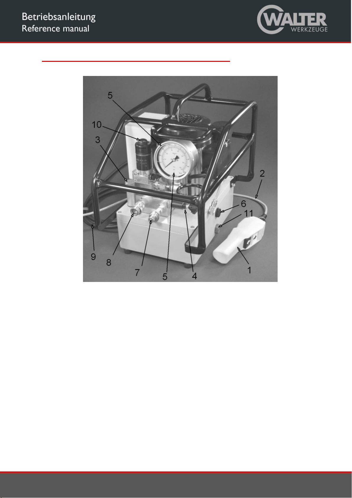
Walter FE055-3-230V User manual

Operating Instructions
Hydraulic pump FE055-3-230V
Hydraulic device
FE055-3-230V

2
Table of content
EC Declaration of Conformity ....................................................................................................................... 3
General Description of the Machine ............................................................................................................ 4
Specified Conditions of Use .......................................................................................................................... 5
Residual risks ................................................................................................................................................ 5
Notes on Transport ...................................................................................................................................... 5
Use and Conditions for Storage.................................................................................................................... 5
Before Initial Operation ................................................................................................................................ 6
Operation ..................................................................................................................................................... 7
Operating the Machine ............................................................................................................................ 7
Pressure and / or Torque Adjustment ...................................................................................................... 7
Tightening or loosening threaded connections ....................................................................................... 7
Servicing and Fault Clearance...................................................................................................................... 8
Shutdown ..................................................................................................................................................... 8
Technical Data .............................................................................................................................................. 9
Electrical Diagram ....................................................................................................................................... 10
Hydraulic Diagram ...................................................................................................................................... 11
Part List for Hydraulic Diagram .................................................................................................................. 12

3
EC Declaration of Conformity

4
General Description of the Machine
Fig. 1
Components of the Machine:
1 Remote control
2 Remote control cable
3 Hydraulic fluid filler cap
4 Pressure adjustment valve
5 Manometer
6 Fluid level sight glass
7 Hose coupling connection "A"
8 Hose coupling connection "B"
9 Mains cable with mains plug
10 Manual actuation for solenoid valve
11 Fluid drain plug

5
Specified Conditions of Use
This device is exclusively intended for professional use as a drive mechanism for hydraulic torque tools in line with
the description and safety instructions given in these Operating Instructions.
Any other use is considered to be improper!
In particular the use of the machine as a drive for all other hydraulic devices such as presses, hoisting
cylinders, hydraulic shears, spreaders, etc. is improper use!
Improper use of the device or modifications to the device undertaken by the end-user exclude any liability
on the part of the manufacturer and invalidate the Declaration of Conformity!
In this case the user is liable for damages resulting from the use of the device.
Residual risks
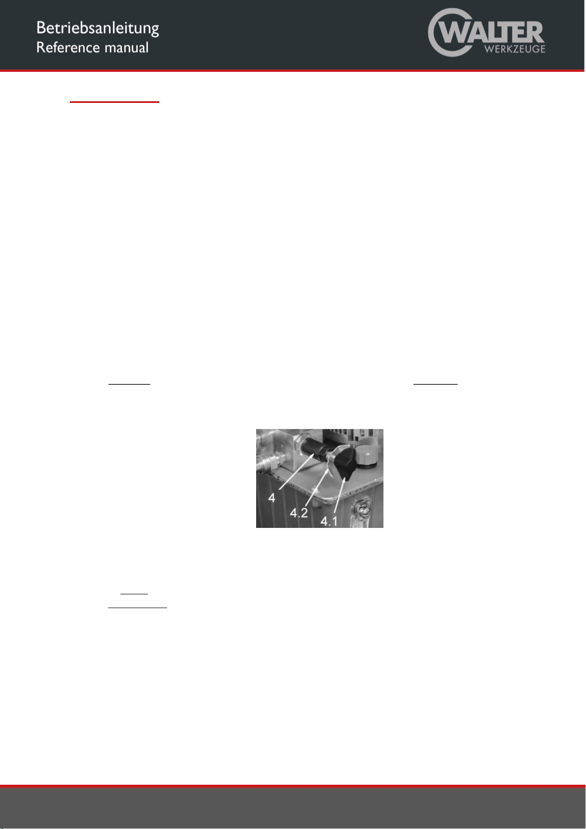
Danger due to hot surfaces: The surface of the oil cooler (if fitted)
becomes hot; keep a safe distance; the warning symbol is attached to the cooler
Danger due to noise: maximum noise level 82 dB(A); the end-user must make personal protective
equipment (ear-protectors) available.
Notes on Transport
Transport of the machine ready for operation:
a. by hand: up to 30 kg with 1 person
above 30 kg with two persons
b. with industrial trucks: use suitable hoisting equipment
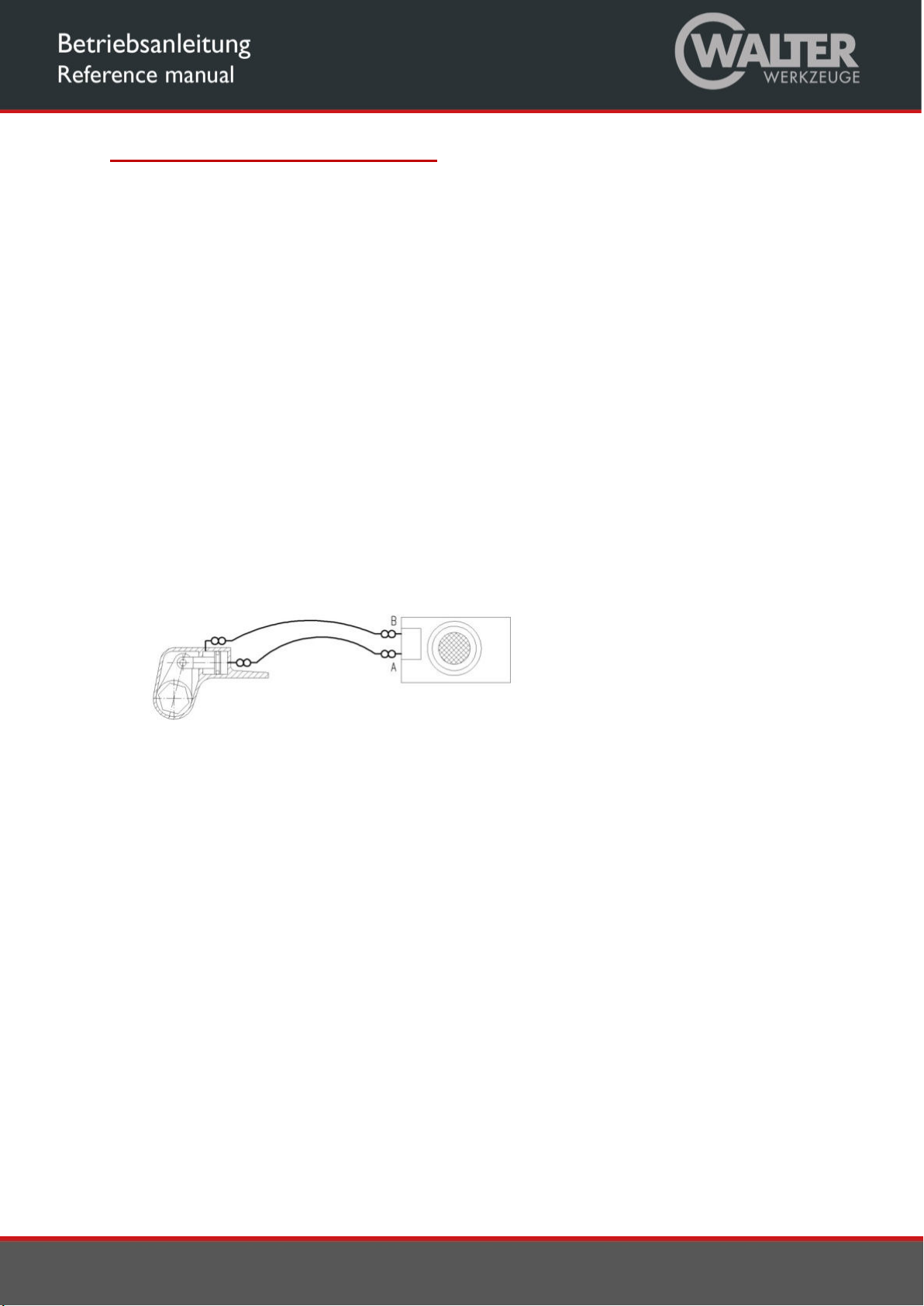
c. hanging: use suitable slings (no chains, no metal ropes). Attachment
point for slings as shown in Figure 2
Fig. 2
Use and Conditions for Storage
Ambient temperature: -10 to +40°C for use and storage
Protect from rain during use and storage.
Modification of the conditions of use only after consultation with the manufacturer.
Power supply connections: (delivery with earthed pin plug). In the event of modification to the mains
connection, protection against shock must be guaranteed by installing a protective earth system.

6
Before Initial Operation
Carry out a visual inspection before each start-up.
Check remote control (1), mains plug (9) and all cables for damage.
Check hose couplings, hoses1) and hydraulic torque tools1) for damage.
1) not included in delivery
Hose couplings, hoses and hydraulic torque tools must be designed for an operating pressure of 700 bar.
Hose couplings, hoses and hydraulic torque tools with lower operating pressures are not permitted to be
connected to the hydraulic device!
Check the entire machine, fluid reservoir, motor, manometer and control box for damage such as
ruptures or leaks.
Have damaged parts replaced by qualified technicians before operation.
Check hose couplings (7, 8) for dirt.
Clean soiled hose couplings before operation.
Check the fluid level; the level must be up to the middle of the oil sight glass (6).
If need be, top up hydraulic fluid.
Set up the hydraulic device on a level, horizontal surface so that it is prevented from falling over or falling
down.
Connect the hydraulic device by means of the threaded couplings with the hoses and with the hydraulic
torque tool: (as per Fig. 3)
Power supply connections: (delivery with earthed pin plug). In the event of modification to the mains
connection, protection against shock must be guaranteed by installing a protective earth system.
Fig. 3
The hydraulic device must not be operated without the hoses and the hydraulic torque tool connected
up!
Connect the hydraulic device to the electricity supply.

7
Operation
Operating the Machine
Switch on the motor by actuating the white push-button on the remote control (1).
White push-button actuated: forward stroke of the tool piston
White push-button not actuated: return stroke of the tool piston
Switch off the motor by actuating the black push-button on the remote control (1)
Relieve pressure of the device by manually actuating the solenoid valve (10)
Pressure and / or Torque Adjustment
The torque of hydraulic torque wrenches is proportional to the pressure.
This is why before tightening or loosening bolted connections the maximum pressure of the machine and
thus the maximum torque of the torque tool must be adjusted:
Do not place the hydraulic tool on either bolts or nuts.
Switch on the motor by pushing the white push-button on the remote control (1) and keep the white push-
button pressed down – the tool piston extends.
After reaching the end position of the tool piston, the maximum pressure of the system can be increased
by turning the adjustment knob (4.1) on the pressure adjustment valve (4) clockwise until the required
pressure is reached. The current system pressure is displayed on the manometer (5).
By releasing the white push-button, the tool piston retracts.
Fig. 4
Checking the setting: after reaching the end position a second time, press the white push-button again in
order to extend the tool piston completely and to keep it until the maximum pressure is reached.
To reduce the maximum pressure, turn the adjustment knob (4.1) on the pressure adjustment valve (4)
anti-clockwise.
When the required pressure is reached, the setting is secured by tightening the wing nut (4.2) on the
pressure adjustment valve (4).
Tightening or loosening threaded connections
Tightening or loosening threaded connections is done according to the instructions of the torque tool
manufacturer.

8
Servicing and Fault Clearance
As a matter of principle, electrical work may only be carried out by qualified electricians.
Use only original spare parts as per the spare parts list.
Hydraulic fluid change and filter change (if fitted) at least once every year or at the latest after every 300
operation hours; if necessary earlier, if the hydraulic device is used in a dusty environment.
Recommended hydraulic fluids: HLP32 or HLP46
Hydraulic fluid quantity : see Technical Data (Section 11)
No Filling filter available! When filling, ensure that no dirt or foreign matter enters into the oil
container
Fluid filter as per spare parts list
Malfunction
Possible cause
Remedy
Motor does not start
Mains cable not connected
connect Mains cable
Incorrect mains voltage
Check mains voltage; if
necessary connect
to suitable electricity supply
Mains cable faulty
Remote control cable faulty
Remote control faulty
Have it replaced by qualified electrician
Machine faulty
Have it serviced by authorised workshop
No (or insufficient) pressure
build-up even though motor
is running
Too little or no hydraulic fluid
Top up hydraulic fluid
Maximum pressure not set or
set too low
Adjust pressure as per Section 8
.2
Machine faulty
Have it serviced by authorised workshop
Tool does not move even
though pressure builds up
correctly
One or several hose couplings
not tightly connected
Connect up machine,
hoses and tool as per
Section 7, Fig. 2
Tool works the wrong way
round
Tool connected incorrectly
Connect up machine, hoses and tool as per
Section 7, Fig. 2
Shutdown
Switch off motor by actuating the black push-button on the remote control (1).
Release the pressure in the system by pressing the manual operation of the solenoid valve (10).
Disconnect the hydraulic device from the mains.
Turn the adjustment knob on the pressure adjustment valve (4) all the way anti-clockwise and thus set
the maximum pressure to 0 bar.
Disconnect the hydraulic device from the hoses.

9
Technical Data
Fig. 5
Type FE055-3-230V
Technical Data
Voltage 1~230V 50Hz
Nominal power output 0,55 kW
Pump capacity:
Low pressure < 75 bar 6.5 l/min
Medium pressure 75-220 bar 1.8l/min
High pressure up to 700bar 0.7 l/min
Weight without/with hydraulic fluid 25/29 kg
Fluid capacity 4.0 l
Fluids: HLP32; HLP46
Dimensions:
Length 40 cm
Width 28 cm
Height 40 cm
Noise level 82 dbA

10
Electrical Diagram

11
Hydraulic Diagram

12
Part List for Hydraulic Diagram
Part List / Stückliste
FE055-3-230V
Part N°
Denomination
Type
C
haracteristics
Manufacturer / Supplier
10006
Pressure Relief Valve
MVE4 AR
12l/min; 700bar
HAWE
10009
Pressure Relief Valve
DBV 100
5l/min; 250bar
Stephan Dahlmann M.u.A. GmbH
10010
Shut Off Valve
AV75
12l/min; 700bar
Stephan Dahlmann M.u.A. GmbH
10041
Shut Off Valve
AV250
5l/min; 700bar
Stephan Dahlmann M.u.A. GmbH
10041
Electric Motor
ECS71G2 230V
0,55 kW
EMGR
10065
4/2Way Solenoid Valve
G4
-
1 R G205V
12l/min; 700bar
HAWE
10094
Pressure Relief Valve
DBV750
5l/min; 750bar
Stephan Dahlmann M.u.A. GmbH
10095
Oilfilter
OC 90
25l/min; 10um; 16 bar
Knecht/Mahle
10168
Piston Pump
PE6
0,21ccm/1; 700bar
HAWE
10169
Piston Pump
PE8
0,38ccm/1; 700bar
HAWE
10170
Piston Pump
PE15
1,32ccm/1; 250bar
HAWE
20374
Check Valve (2x)
RK0
10l/min; 700bar
HAWE
20583
Oil Cooler
119
-
50
-
M
22
25l/min; 10bar
Setrab
This is a transcription or translation of the original operating instructions of Stephan Dahlmann - Mechanik und Antriebstechnik GmbH
Table of contents
Popular Water Pump manuals by other brands

Bizon Pumps
Bizon Pumps BPN-330C installation instructions

Grundfos
Grundfos Unilift CC 5 Installation and operating instructions

Lincoln
Lincoln 2710 manual

Dutypoint
Dutypoint ScubaTANK WX1-3040-1050-AB.A Operation & maintenance manual

SKC
SKC Flite 3 operating instructions

Eurovacuum
Eurovacuum EVPP Series Installation and operating manual

Bacharach
Bacharach QV2 Operation and maintenance instruction manual

Faller
Faller 180627 quick start guide

Grundfos
Grundfos SMART Digital XL DDA instructions

Aquatec
Aquatec Aquapro AP200LV instruction manual

AMT
AMT 3993-99 Specifications information and repair parts manual

Graco
Graco Falcon A Series instructions