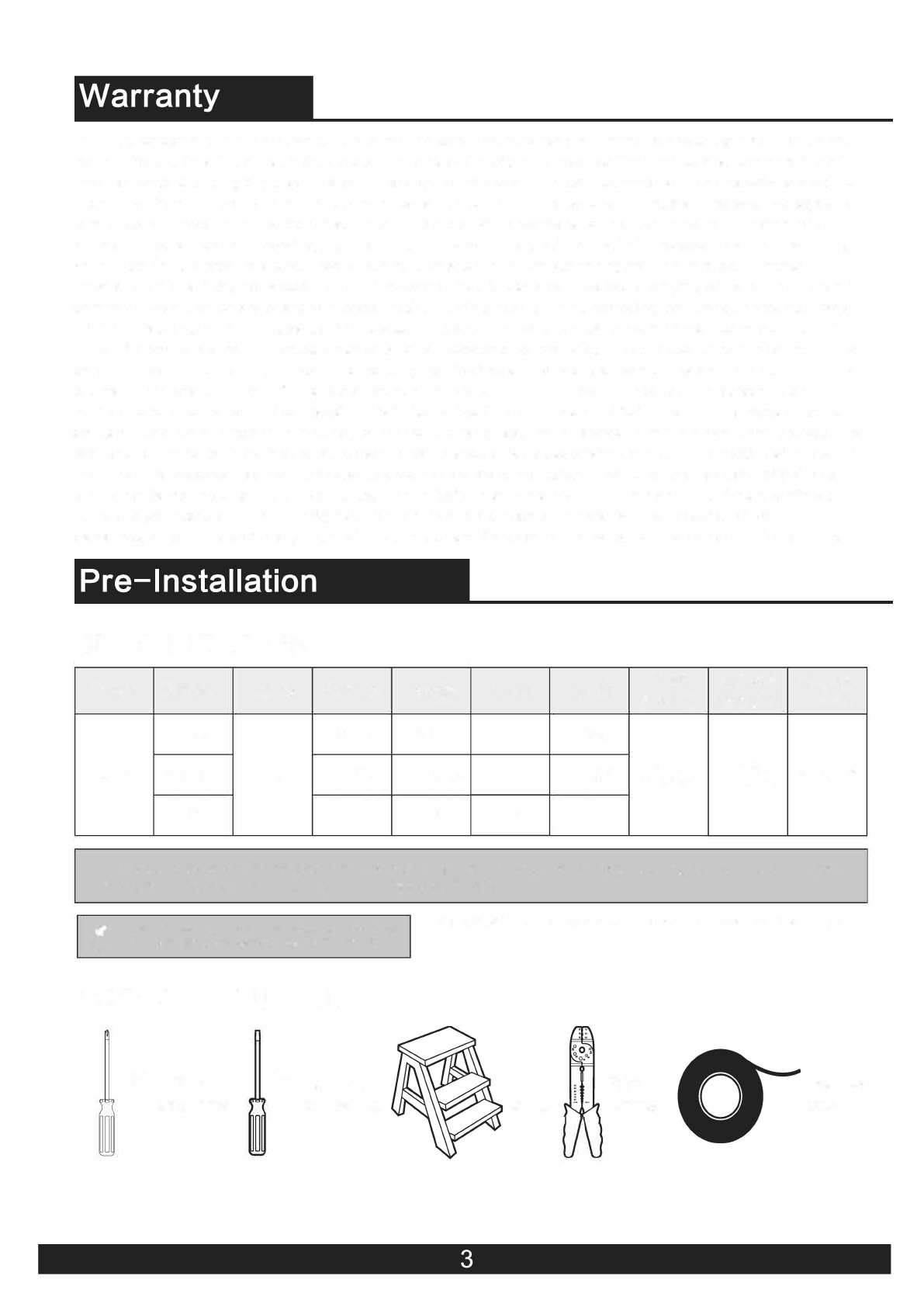
Warehouse of Tiffany CFL-8283 User manual

USE
AND
CARE
GUIDE

Safety
Information
Pre-Installation
Hardware
included
Celing
················································
2
················································
3
................................................
4
Attaching
the Fan
Blades
················································
7
Attaching
the
Lights
................................................
8
Install
the
crystal
shade
................................................
g
················································
5
················································
6 Use
of
remote control
•···············································
1o
Hanging
the
Fan Care and
cleaning
················································
11
1,
To
reduce
the
risk
or
electrical
shock
the
electricity
has
been
turned
off
at
the
circuit
breaker
or
fuse
box
before
begin.
2,
All
wiring must
be
in
accordance
with the National
Electrical
Code NASVNFPA
70-1999
and local electrical codes.
Electrical installion should be performed
by
a qualified
licensed electrician .
3, Tne
outlet
box and
support
srtructure
must be
securely
mounted and capable
of
reliably supporting
35ib.(15.9kg).Use
only
UL listed
outlet
boxes marked
"Acceptable
for
Fan
Support
of
35ibs(15.9kg)or
less."
4,
The fan must be mounted
with
a
minimum
of
7 ft. (2m)
clearance from the trailing edge
of
the blades
to
the floor.
5, Do
not
operate the reversing switch while thefan blades
are in motion.
You
mustturn the fan
off
and stop the
blades before you reverse the blade direction.
6,
Do
not
place objects in the path
of
the blades.
7,
To
avoid
personal
injury
or
damage
to
the
fan
and
other
items
use
caution
when
working
around
or
cleaning
the
fan.
8,
Electrical diagrams are
for
reference only. Light kits
that
are
not
packed
with the
fan
must
be
UL-listed and marked
suitable
for
use
with the model fan you are installing.
Switches must be
UL
General
Use
Switches. Refer
to
the
instructions packaged with the light kits and switches
for
properassembly.
9,
Aftermaking electrical connections, spliced conductors
should be turned upward and pushed carefully
up
into
tne outlet box.The wires should be spread apartwith the
grounded conductor and the equipment-grounding
conductoron one side
of
the outlet box.
10,
All setscrews must be checked and retightened where
necessary before installation.
WARNING:TO reduce
the
risk
of
personal injury,
do
not
bend
the
blade brackets (also referred
to
as
flanges)
during
assembly
or
after
installation.Do
not
insert
objects
in
the
path
of
the
blades.
WARNING: Remove
the
rubber
motor
stops on
the
bottom
of
the
fan
before
installing
the
blades
or
testing
the
motor.
WARNING:
To
reduce
the
risk
or
fire
or
electric
shock,do
not
use
this
fan
with
any
solid-state
speed
control
device.
WARNING:To
avoid
possible electrical shock,
turn
the
electricity
off
at
the
main fuse
box
before
wiring.It
you feel you
do
not
have
enough
electrical
wiring
knowledge
or
experience,
contact
a licensed
electrician.
WARNING: Electrical
diagrams
are
for
reference
only. Optional use
of
any
light
kit
shall be UL-listed
and marked
suitable
for
use
with
this
fan.
WARNING:
To
reduce
the
risk
of
fire,
electric
shock,
or
personal
injury.
mount
to
outlet
box
marked"
Acceptable
for
fan
support
of
35
ibs.(15.9
kg)or
less." and use
the
screws
provided
with
the
outlet
box.

SPECIFICATION
Size Speed Volts Amps Watts RPM CFM Net Gross Cube
Weihgt Weight Feet
The above data are for reference only, Actually the motor speed of each ceiling fan is a little different.
Any products, Subject to actual products as standard.
TOOLS REQUIRED
Phillips
screwdriver
8 Flat blade
screwdriver
Step
ladder
Wire
stripper
Electrical
tape

HARDRE INCLUDED
components table
PACKAGE CONTENTS
A
K
BB
cc
DD
EE
FF
GG
Blade attachment screw and fiber washer
Plastic wire nut (not to scale)
Blade arm screw and lock washer
< hand pull chain only>
Mounting screws
Expansion Bolts
Balanced parts package
1 L
B ! C !
16
1
2
2
1
1
1 E I
I
D
F 1
G
H 1
1
1 J 1

Installation
of
the
hanging
bracket
(suspension
part)
LLLLLLLLLLLLLLLLLL
LL
~~~~~~
~
~
LL ~~
LLLL
cc
t:DDO:a:e::rn:::ceHina
cc
LLL~LLLLLLL
~
~LL
~
LL
Washers<C>
For
wooden
ceiling,
use
wood
screw
to
drill
on the
wooden
beam
or
the
"junction
box" to
fix
the
hanging
bracket
(selection
is
made
according
to
actual
requirements
of
the
customers).
Se"
<aoo
""
scrnw<S>J~1
: :
STEP 1A-WOODEN CEILING
SWITCH OFF THE
ELECTRICAL
MAINS AT THE
CIRCUIT
BREAKER
FUSE BOX.
1)Use the Mounting Bracket (A) as a guide, mark the
spots
where the 4
Self
Tapping Screws (B) will be drilled.
2)Remove
the Mounting
Bracket
{A), drill 4 holes
for
3MM diameter, install the
mounting
bracket
onto wooden ceiling with the 4
Self
Tapping Screws (B) &
Washers (C).
' f ' ; ;
' ·,
A
IMPORTANT:
SCREWS
MUST
BE
TIGHTENED TILL SNUG
Note: According to the ceiling
of
different
materials, use
different
screws
to
fix
the hanging bracket.
Don't fix the hanging bracket on the wood ceiling less than 12MM to prevent
danger
caused
by
loosening
of
screws.
After
the hanging
bracket
is completed, ensure that
it
can
withstand
the
tension
test
of
more
than 68KG
for
safety.
Mountin
Brackef<A>
~
1
½r
1
7
For
concrete
ceiling,
use the
percussion
bit
with
diameter
8mm to drill
holes
according
to the length
of
expansion
screws.
Then use the
attached
expansion
screws
to
fix
the
hanging
bracket
onto
the
ceiling
(selection
is
made
according
to
actual
requirements
of
the
customers).
STEP
2A-CONCRETE
CEILING
■
1
111
&
SWITCH OFF THE
ELECTRICAL
MAINS AT THE CIRCUIT
BREAKER
FUSE BOX.
1)Use the Mounting
Bracket
(A) as a guide, mark the
spots
where the 4 Expansion
Bolts (B) will be drilled.
2)Remove the Mounting Bracket (A), drill 4 holes and
insert
4 Expansion Bolts (2)
into the concrete ceiling, install the mounting
bracket
and secure with Flat
Washers (C), Spring Washers (D) and Nuts (E).
IMPORTANT: SCREWS & NUTS MUST
BE
TIGHTENED
TILL
SNUG
The
first
step
of
the
suspension
motor
E12
MAX40W*3PCS
1.
Unscrew
the
three
screws
of
the
motor
cover.
2.Screw
the
E
12
bulb
with
the
appropriate
wattage
into
the
socket.
3.
Insert
the
motor
outer
cover
into
the
motor
and
tighten
the
screw.
1. Thread the
suspender
through the
suspended
clock and coupling
cover.
2.Then insert the tail
of
the
suspender
from the lifting head
of
the motor.
3.After
the lateral pin is threaded
out
from the suspended head position,
insert
R type pin.
4.Tighten the lifting head screws.
5.Hang the fan
of
the hanging pipe into the hanger.

1 Making the electrical connections
WARNING:Each
wire
not
supplied
with
this
fans
is
designed
A\
to
accept
up
to
one
12-gauge
house
wire
and two
wires
from 0 IMPORT
ANT:
Use
the
plastic
wire
connectors(BB)
supplied
with
your
fan.
Secure
the
connectors
with
electrical
tape
and
ensure
there
are
no
loose
strands
or
connections.
~
the
fan.If
you
have
larger
than
12-gauge
house
wiring
or
more
than one
house
wire to
connect
to
the
fan
wiring,cnsult
an
electrician
for
the
proper
size
wire
nuts
to
use.
NOTE:The
fan
comes
with
54in.Lead
wires
for
use with an
extended
ball/downrod
assembly.
If
using
the
4.5in.ball/downrod
assembly{B)provided
youcan
cut
the
lead
wires
to
your
desired
length{no
sooner
than 12in.).
A\
WARNING:Remove
the
rubber
motor
stops
on the bottom
of
~
fan before
installing
the blades
or
testing
the
motor.
-----1
BLACK
t---7--CJ----I
AC IN <L>
-----
._
__
~BLU
Et----
mj
---WHITE---,----11
AC
IN
<N>i,-1
---
-----.---------iG
REENf-----r7----il
Ground
wire
1.The
motor
"green"
wire
to
the
"Ground
wire"wire
from
outside
Outlet
Box.
2.The
motor
"white"
wire
to the "AC IN
<N>"wire
from
outside
Outlet
Box.
3.The
motor
"black"
wire
to the "blue
"wire
to the "AC IN
<L>"wire
from
outside
Outlet
Box.
4.Finally,put
the
connected
wires
in
the
hanger.
<Hand
Pull
Chain
ONLY>
Preparing
for
mounting
<Hand
Pull
Chain
ONLY>
Lj
\____________,..)
1
:Remove
the
mounting
bracket
from
the
canopy
by
loosening
the
two
canopy
screws
located
in
the
L
shaped
slots.
2:Remove
and
save
the
two
canopy
screws
in the round holes.
This
will
enable
you to
remove
the
mounting
bracket
/..
Install remote control
1.Carefullypush the canopy to the bottom
of
the mounting
bracket,
make
two
sliding
holes
aligned
to
the
two
prominent
screws on the mounting bracket, and then turn clockwise
until tight.
2.Push the canopy ring to the bottom
of
the canopy,
slide the
inner
holes aligned to the two prominent screws
on
the
mounting
bracket
again,
and
turn
the
canopy
ring
\ clockwise until tight.
·•
.....
remote
control
<ONLY>
Preparing for mounting
l l
1:Remove the mounting bracket from the
canopy
by
loosening the two
canopy
screws located
in
the
L shaped slots.
2:Remove and save the two
canopy
screws
in
the
round holes. •
This will
enable
you
to
remove
the
mountingbracket
.••••
/

1 Attaching the blades to the arms
9 ,
I I
f 1:Pass the red
washer
through
the screw.
I d 2:Tighten the
screw
through
the
blade
and
tighten
it
on the arms.
3:Repeat
the
above
steps
to
tighten
the
four
sets
of
blades.
0
01
I I
I I
I I I
1-
-:1~
2 Fastening the blade arms to the
motor
A\
WARNING:Remove
the
rubber
motor
stops
on
the
bottom
Ll.1
of
the fan
before
installing
the
blades
or
testing
the
motor.
NOTE:Your
fan
features
revolutionary
advancements
for
quick
and
easy
blade
installation.Including
an
alignment
post and
captive
blade arm screws.
NOTE:Your
fan blades are
reversible.Select
the
blade
side
finish which best
accentuates
your
decor.
1:
Fasten the arm to the
fan-motor
assembly
by
inserting
the
alignment
post
int
the
slot
on the
bottom
of
the
motor
and
tightening
the pre-
installed arm screws.
2:
Repeat
this
step
for
the
remaining
blade
assemblies.

f4ti14hi§PW1,
-
bht•il
- ·
1
Connecting
lamp
wire
1
Attaching
the
light
kit
fitter assembly
CAUTION
:To reduce
the
risk
of
electric
shock.disconnect
the
electrical
circuit
to
the
fa
before
installing
the
light
fixture.
1.lnsert
the "white" line in the
switching
box
of
the
motor
into the
"white"line
of
the
light
and tie
insulated
rubber
tape.
2.lnsert
the
"bule"line
in the
switching
box
of
the
motor
into the
"blue"line
of
the
light
and tie
insuklated
rubber
tape.
2
Tighten
the
screw
of
the
box cover.
1.Take the
wire
into the
switching
box
of
the motor.
2. Align the opening
of
switchiong
box
of
the
light
at
switch locking position
of
the
positive
and
negative
rotation
of
the
motors
witching
box.Place
the
cover.Screw
in the
screw
of
the
switching
box.

Install the shade
t
E26 MAX 60W*3PCS
OPERATING YOUR FAN
(XX)
U
�
A
A
CAUTION:

ILOwl
FanSpeed Low Level
IMEDI
FanSpeed Middle Level
[Bil
FanSpeed High level
ISTOPI
FanSTOP
LIGHT
NO/OFF LIGHT NO/OFF
[8]
Auto off after 1
hr
~
Auto offafter 2hr
~
Auto offafter4hr
ru:i)
Auto off after 8hr
From controller
remote control <ONLY>
FORAC
IN
L
FORAC
INN
Ground wire
1
:The
motor
"green"
wire
to
the
"Ground
wire"wire
From
outside
Outlet
Box.
2:The
motor
"black"
wire
to the
remote
control
"black"
wire
From
Remote
control(receiver)
3:The
motor
"purple"
wire
to
the
remote
control
"purple"
wire
From
Remote
control(receiver)
4:The
motor
"blue"
wire
to
the
remote
control
"blue"
wire
From
Remote
control(receiver)
5:The
motor
"white"
wire
to the
remote
control
"white"
wire
From
Remote
control(receiver)
6:Put
the
remote
control
transmitter
into the
ceiling
canopy.
7:The
Remote
control(receiver)
"black"wire
to the "AC
IN
L"wire From
outside
Outlet
Box.
8:The
Remote
control(receiver)
"white"wire
to the "AC
IN
N"wire From
outside
Outlet
Box.
9:Use
the
remote
control
to
start
using
the
ceiling
fan lamp.

WARN
□
□
□
□
□
□
□
□
□
□
□
□
□
□
□
□
□
□
□

S
eries general specifications
USE AND CARE GUIDE
Table of contents
Other Warehouse of Tiffany Fan manuals
Popular Fan manuals by other brands

Rubine
Rubine FABIO Series user manual

NuAire
NuAire MRXBOXAB-ECO4-1Z installation manual

Schaefer
Schaefer VAF8000A/A-3/B-3 Owner's manual & safety instructions

minkaAire
minkaAire Craftsman F840 instruction manual

Taurus Alpatec
Taurus Alpatec FRESKO FOREST 3B Instructions for use

EQUATION
EQUATION FZ10-17JR Assembly-Use-Maintenence Manual