WarmFlow Nero BT110 User manual

Buffer Tank Manual
Incorporating: User Instructions
Installation Instructions
Commissioning Instructions
Maintenance Instructions
Nero Buffer Tank
Stainless Steel Buffer Tanks
Products covered by this manual:
Buffer Tank
BT110
BT200

INSTALLATION, COMMISSIONING & SERVICING
All works to this product including installation, commissioning, service or repair must be conducted
only by appropriately certified and competent persons in accordance with all manufacturer’s
instructions contained herein, as well as all current related legislation, regulations, standards,
codes and by-laws applicable to the territory of installation.
This product must be installed, commissioned, serviced or repaired only by a competent person
in accordance with the current:
• IEE Regulations, Building Regulations,
• Building Standards (Scotland) (Consolidation),
• Building Regulations (Northern Ireland),
• Local water by-laws,
• Health and Safety Document 63S (the Electricity at Work Regulations 1989),
• IS813 (Eire)
• and other local requirements
• Where no specific instruction is given, reference should be made to the relevant codes of
Practice:
– BS7074:1 : Code of practice for domestic and hot water supply
– EN:12828 : Central heating for domestic premises
The product must be registered with the manufacturer according to the terms and conditions of
the related product guarantee. See Section 6.
This product must be serviced annually by appropriately certified and competent persons, and
proof of servicing e.g., receipts/invoices, must be retained by the User.
A full statement of the guarantee applicable to this product is included in Section 6 of this manual.
FAILURE TO CORRECTLY INSTALL, REGISTER AND ANNUALLY
SERVICE THIS PRODUCT WILL INVALIDATE ALL GUARANTEES

TECHNICAL, SPARES & GUARANTEE CLAIMS
For technical advice about the installation, use and servicing of this appliance, please contact the
Warmflow Customer Care Centre. Please also refer to our website www.warmflow.co.uk.
Should replacement components be required, a list of available spares is provided in Section 4.2,
page 7. Only Warmflow spare parts must be used with this product.
In the unlikely event that replacement components might be required within the guarantee period,
please notify the Customer Care Centre stating the serial number of the appliance, the nature of
the fault and the part number of the replacement components required.
For Parts, Service, Technical & Customer Care
Great Britain & N. Ireland: 028 9262 1515
Republic of Ireland: 048 9262 1515
HEAD OFFICE GB OFFICE
Lissue Industrial Estate, Moira Road, Unit C4, Stafford Park 4,
Lisburn, Co. Antrim, N. Ireland, BT28 2RF Telford, TF3 3BA
Tel: (028) 9262 1515 Tel: (01952) 607 750
Fax: (028) 9262 0869 Fax: (01952) 603 983
E-mail: sales@warmflow.co.uk E-mail: salesgb@warmflow.co.uk
technical@warmflow.co.uk technical@warmflow.co.uk
service@warmflow.co.uk service@warmflow.co.uk
WEBSITE
www.warmflow.co.uk

CONTENTS
1Product Information ............................................................................................................1
1.1 Handling & Storage. ...................................................................................................................1
1.2 Intended Use..............................................................................................................................1
1.3 Technical Data. ..........................................................................................................................1
1.4 User Warnings. ..........................................................................................................................2
2Installation ...........................................................................................................................3
2.1 General Requirements. ..............................................................................................................3
2.2 Connections. ..............................................................................................................................5
2.3 Fitting the Thermostat/Sensor. ...................................................................................................6
3Commissioning....................................................................................................................6
3.1 General Requirements. ..............................................................................................................6
4Servicing ..............................................................................................................................7
4.1 General Requirements. ..............................................................................................................7
4.2 Replacement Parts.....................................................................................................................7
5End-of-Life Information....................................................................................................... 8
5.1 Safety Risks ...............................................................................................................................8
5.2 Disassembly of the Product........................................................................................................8
5.3 Casing and Key Components.....................................................................................................9
6Guarantee........................................................................................................................... 10

Page 1of 11
1 PRODUCT INFORMATION
1.1 Handling & Storage.
Prior to installation, this product must be handled with care and stored upright in a clean and
dry location, in its original packaging. All packaging materials are environmentally friendly and
can be recycled.
1.2 Intended Use
The product is designed to act as a buffer tank as part of a hydronic heating system only.
The product must only be filled with heating system water, which has been dosed with the
correct concentration of corrosion inhibitor. The concentration of corrosion inhibitor chemicals
present within the heating system water must be tested and maintained in accordance with
the inhibitor manufacturer’s instructions at installation and as part of the annual service of the
heating system, and upon any occasion when water is lost from and restored to the heating
system.
The product is not for use in the storage of potable water or domestic hot water.
The product is not intended for use in conjunction with water provided by a private source.
1.3 Technical Data.
Figure 1. Buffer Tank components and dimensions

Page 2of 11
1.4 User Warnings.
Do not use the product for any purpose other than its intended use.
Use of the product in any way other than that outlined in 1.2 above is an infringement of the
intended purpose of this product and invalidates all guarantees.
Damages or losses resulting from improper use are excluded from coverage by the product
guarantee.
Do not remove or adjust any part of the product. Never attempt to work on or repair the
product yourself.
Risk of Scalding: During the operation of this product water temperatures within may reach
60°C.
If the buffer tank develops fault, switch off the source of heat and isolate all electrical supplies.
In all cases of fault contact the original installer or other competent person before contacting
Warmflow.
Frequent or routine topping up of the heating system to which this product is attached should
not be necessary and may prove harmful to the heating system including its fabric,
components, heating appliance(s) and this product. Should topping up prove necessary on a
frequent or routine basis you must contact your installer or Warmflow immediately. Where a
need for topping up applies, special consideration must be given to the concentration of
inhibitors within the heating system water and concentrations of inhibitor must be restored
without delay.
Documented records of the annual service of the heating system including this product must
be retained by the user.
BT1
10
BT200
DIMENSIONS
(A) Height (mm)
830
1380
(B) Flow Connections (mm)
530
1080
(C) Thermostat Pocket (mm)
530
868
(D) Return Connections (mm)
257
257
OPERATING DATA
Maximum Operating Pressure (Bar)
3.0
3.0
Rated volume (litres)
107
194
Weight when full (kg)
140
240
Standing heat loss (kWh/24h)
1.43
1.78
FICHE DATA
Supplier Name
Warmflow
Supplier Model Identifier
BT110
BT200
Energy Efficiency Class
C
C
Standing Loss (W)
60
74
Storage Volume (litres)
107
194

Page 3of 11
2 INSTALLATION
2.1 General Requirements.
The product must be installed only by a competent person and in accordance with all
manufacturer’s instructions contained herein, and all current legislation, regulations,
standards, codes and by-laws applicable to the territory of installation.
The product must be installed vertically (not on its side) and in a frost-free, interior location.
Ensure adequate clearances and access around the product for the purposes of installation,
service and maintenance. The installation location must not prevent component parts being
removed for the purposes of service or replacement.
The appliance must be installed on a floor area that is level and capable of supporting the
product when it is full of water. See Figure 1 and associated table for details of product
weights.
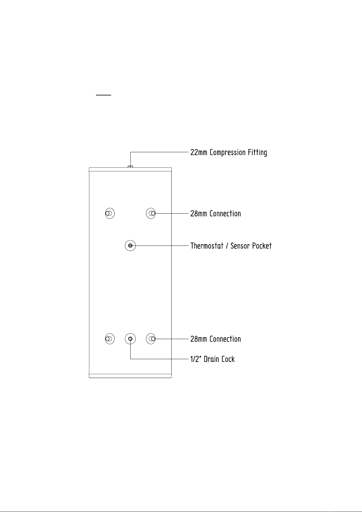
Connection to the product is via compression fittings only (not supplied).
It is recommended that the flow and return pipework connected to the product is fitted with
isolation valves, e.g., quarter-turn ball valves (not supplied), for easier maintenance.
The heating system to which the product is fitted must be installed to current HVAC codes of
practice. Before installing the product to a new or existing heating system, the system must
be thoroughly flushed to clear all deposits or other foreign matter such as solder, steel wool
and copper filings. The heating system must be cleansed, flushed, neutralised and protected
from corrosion in accordance with BS12828, BS12831, BS14336 and BS7593 using suitable
cleansing agent(s) and inhibitor(s) and carried out in accordance with the cleanser/inhibitor
manufacturers’ instructions.
The heating system must be dosed with corrosion inhibitor to the concentration specified by
the inhibitor manufacturer and in consideration of the total volume of the heating system
including all components, pipework, appliances, expansion capacity and this product.
Inhibitor concentration within the heating system must be monitored and maintained as part
of the annual service of the heating system, or upon any occasion when water is lost from
and restored to the heating system. Failure of this product or its components due to corrosion
or the presence of corrosion deposits within the heating system will not be covered by the
related product guarantee.
Heating system pressures must not exceed the maximum permitted. See Figure 1 and
associated table for details. The heating system must incorporate appropriately rated
pressure relief valve(s).
Ensure that the volume of the buffer tank is appropriate to the intended heating system
requirements and performances. Buffer tank capacity must be calculated by a competent
person using recognised principles and sizing formulae.
When sizing the heating system expansion vessel, the storage volume of the buffer tank must
be taken into consideration.

Page 4of 11
Figure 2. Typical installation schematic.
Figure 3. Typical installation schematic with additional low temperature heating
system circuit.

Page 5of 11
2.2 Connections.
See Figure 4.
Connection of the product to the heating system is via the 4 × 28mm pipe connections.
Connection must be via appropriate compression fittings (not supplied).
A thermostat/sensor pocket is inserted to the upper ½” boss of the product as supplied. This
sensor pocket is NOT factory-fitted and is unsealed. It must be fitted and sealed as part of
installation activities.
The lower ½” boss is present on the product in order to facilitate the fitment of a drain valve
(not supplied).
A 22mm connection is present on top of the product in order to facilitate the fitment of an
automatic air vent (not supplied). An air vent must be fitted.
Figure 4.Connections

Page 6of 11
2.3 Fitting the Thermostat/Sensor.
Fit and seal the thermostat/sensor pocket to the product. See Section Figure 4 Connections.
Insert the thermostat/sensor into the thermostat/sensor pocket as shown in 5. Ensure the
sensor is secure.
Figure 5. Thermostat/sensor pocket.
3 COMMISSIONING
3.1 General Requirements.
Initial operation of the heating system must be done with the Installer of the heating system
or other competent person present.
As part of commissioning, the installer or other competent person must:
•Ensure that adequate clearances and access to the installed product have been provided.
•Ensure that all pipework is adequately supported.
•Ensure that all connections to the buffer tank are correct.
•Ensure that all connections are secure and leak-free. Tighten/correct all fittings as
appropriate.
•Ensure that all air is vented from the product and wider heating system.
•Ensure that the air vent fitted to the product is fully closed after venting has been
completed.
•Explain to the User the mode of operation of the heating system and its buffer tank. All
documentation relating to the product must be provided directly to the User by the installer
with all aspects of the user warnings being fully explained (See section 1.4).

Page 7of 11
4 SERVICING
4.1 General Requirements.
Servicing of the product must be included as part of the annual servicing of the heating
system and its appliance(s) and components.
The product must be serviced only by a suitably qualified and competent person and in
accordance with all manufacturer’s instructions contained herein, and all current legislation,
regulations, standards, codes and by-laws applicable to the territory of installation.
The product and its connections and attachments must be visually inspected for signs of
leakage. Where leakage is detected/suspected, remedial action must be taken.
Ensure that all controls and safety devices within the heating system are operating correctly.
The concentration of corrosion inhibitor chemicals present within the heating system water
and product must be tested and maintained in accordance with the inhibitor manufacturer’s
instructions as part of the annual service.
Documented records of the annual service of the heating system including this product must
be retained by the User.
4.2 Replacement Parts
Part description Code
Triple Pocket 2205

Page 8of 11
5 END-OF-LIFE INFORMATION
Warmflow Buffer tanks must be disposed of according to local regulations by using a
public or private waste collection service.
5.1 Safety Risks
Prior to disassembly, the appliance should be electrically isolated and disconnected.
Any fluids within the appliance must be drained and disposed of in-line with local
regulations.
Care should be taken when handling the appliance due to weight. Use appropriate
PPE and lifting aids.
Polyisocyanurate foam insulation – suitable PPE should be used for respiration
protection, and to avoid skin or eye contact.
5.2 Disassembly of the Product
The main materials of the components are:
Mild Steel
Stainless Steel
Polyisocyanurate Foam
Plastic Components
These may be recycled – depending on the local recycling facilities available.
The appliance is assembled by using mechanical fasteners and can be disassembled
with standard tools.
The components of a typical appliance are shown below (not all components may be
fitted, depending on appliance specification).

Page 9of 11
5.3 Casing and Key Components
Figure 6. Casing & Key Components
Item Description Main Materials Special Notes
1 Casing Coated Galvanised Steel
2 Foam Insulation Polyisocyanurate Foam Wear Appropriate PPE
3 Storage Tank Stainless Steel
4 Casing Top Plastic
5 Casing Base Plastic
Various other brackets, fasteners and components may be used, with up to 5% of
appliance weight.

Page 10 of 11
6 GUARANTEE
Warmflow Buffer tanks must be disposed of according to local regulations by using a
public or private waste collection service.
Warmflow Buffer Tanks are supplied with the following guarantees from the date of
purchase:
(a) A 2-year guarantee on the duplex stainless steel buffer tank body against defects
of material.
(b) A 2-year guarantee on all parts and components as well as any defects that may
have occurred from time to time during the normal manufacturing process of the
buffer tank as carried out by those exercising all relevant skill and experience and
complying with all relevant legislation, regulations, standards and codes of practice
relating to the manufacturing process.
1. The guarantees provided are from the date of purchase and are conditional upon:
1.1the unit being installed and commissioned by competent persons in accordance
with the manufacturer’s instructions and all legislation, regulations, standards,
codes and by-laws in force at the time;
1.2 the product being registered with Warmflow within 30 days of installation and
the guarantee registration completed and returned to Warmflow along with
evidence of the date of purchase;
1.3 the unit not being modified in any way, or misused or subject to neglect;
1.4 the unit being serviced annually by competent persons in accordance with the
manufacturer’s instructions and legislation, regulations, standards, codes and
by-laws in force at the time;
1.5each service record being completed and proof of purchase and servicing being
retained and made available to Warmflow in respect of any claim being made
under the terms of this guarantee;
1.6the unit being used solely for its intended purpose, not used for the storage of
potable water or domestic hot water or used in conjunction with water from a
private source.
Failure to comply with any of the conditions outlined in this clause will invalidate the
guarantee in its entirety.
2. The guarantee is not transferable and excludes:
2.1labour costs associated with the replacement of the unit or its components;
2.2any defects that appear after the customer makes any modification or alteration
to the unit;
2.3defects caused by the improper use or storage of the unit and in particular (but
without limitation) Warmflow shall not be liable in the case of defects arising
from normal deterioration or improper or faulty handling, operation or
processing of the unit by the customer;
2.4consequential losses however caused.
3. If within the 2-year guaranteed period, as set out at (a) and (b) above, a material
defect is discovered in the Unit:

Page 11 of 11
3.1the customer must send written notification following discovery giving
particulars and either at their own expense and risk shall return the unit to
Warmflow within 2 weeks of written notice being provided by Warmflow; or (at
Warmflow’s sole option) shall permit Warmflow to inspect same; and
3.2if such defect has arisen from faulty materials employed or workmanship carried
out by Warmflow and is existing but not reasonably discoverable upon
inspection at the time of receipt then Warmflow shall supply such part(s) free of
charge along with the costs of transporting same to the customer.
3.3The replacement parts must be fitted in accordance with the terms of the
guarantee set out above.
3.4The replacement parts shall be covered under this guarantee for the remainder
of the unexpired term of two years.
3.5Invoices for callout and/or repair by any third party or parts supplied by a third
party will not be accepted unless previously authorised by Warmflow in writing.
4 Warmflow’s liability for defective units is limited in all circumstances to delivery of
parts for the defective unit and the customer shall accept same as fulfilment of
Warmflow’s obligations.
5 Warmflow disclaims all other warranties whether express, implied or statutory.
Your statutory rights are not affected.
6 This guarantee applies to Warmflow buffer tanks installed on the UK mainland
(excluding Scottish Isles), Isle of Man, Channel Islands, Northern Ireland and
Republic of Ireland only. Provision of in-warranty cover elsewhere is subject to the
agreement in writing of Warmflow.

WARMFLOW Engineering Company Limited
Lissue Industrial Estate, Moira Road, Lisburn BT28 2RF
Tel: 028 9262 1515 Fax: 028 9262 0869
WARMFLOW Customer Care Centre
UK: 028 9262 1515 ROI: 048 9262 1515
Email: service@warmflow.co.uk
THIS MANUAL IS ACCURATE AT THE DATE OF
PRINTING (E&OE) BUT MAY BE SUPERSEDED
AND SHOULD BE DISREGARDED IF
SPECIFICATIONS AND/OR APPEARANCES ARE
CHANGED IN THE INTERESTS OF CONTINUED
PRODUCT IMPROVEMENT.
8788 Rev A May 2023
This manual suits for next models
1
Table of contents
Other WarmFlow Heater manuals