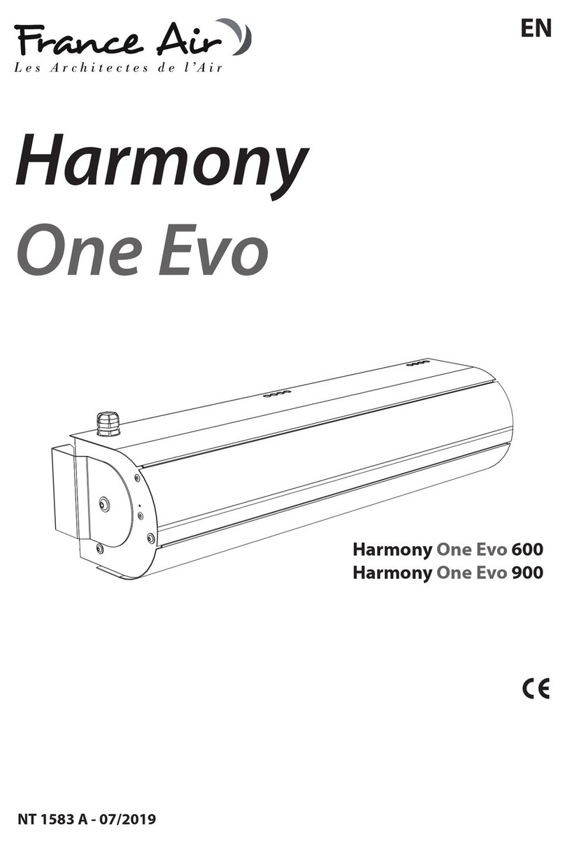
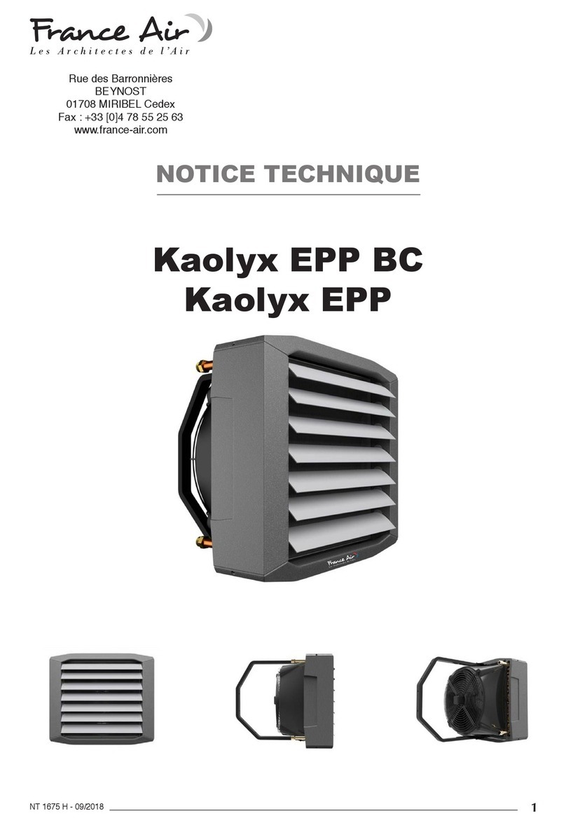
France Air Kaolyx EPP BC Series User manual

Rue des Barronnières
BEYNOST
01708 MIRIBEL Cedex
Fax : +33 [0]4 78 55 25 63
www.france-air.com
NOTICE TECHNIQUE
Kaolyx EPP BC
Kaolyx EPP
NT 1675 E - 09/2017
1

NT 1675 E - 09/2017
2
1 - GENERAL INFORMATION ..........................................p. 3
2 - APPLICATION..............................................................p. 3
3 - TECHNICAL DATA .......................................................p. 4
4 - INSTALLATION ............................................................p. 6
4.1. INSTALLATION - BRACKET...........................p. 7
4.2. ASSEMBLY INSTRUCTIONS .........................p. 7
5 - CONTROLS .................................................................p. 8
5.1 - CONTROL EQUIPMENT...............................p. 8
5.2 - CONNECTION DIAGRAMS ..........................p. 9
5.2.1 - Kaolyx AC...........................................p. 9
5.2.2 - Kaolyx EPP BC ................................p. 14
6 - START-UP AND OPERATION....................................p. 15
1 - INFORMATIONS GÉNÉRALES...................................p. 3
2 - APPLICATION..............................................................p. 3
3 - DONNÉES TECHNIQUES...........................................p. 4
4 - MONTAGE ...................................................................p. 6
4.1. MONTAGE - CONSOLE ..................................p. 7
4.2. INSTRUCTION DE MONTAGE........................p. 7
5 - AUTOMATISME ...........................................................p. 8
5.1. - LES ELEMENTS D’AUTOMATISME..............p. 8
5.2. - SCHEMAS DE CONNEXION.........................p. 9
5.2.1 - Kaolyx AC .............................................p. 9
5.2.2 - Kaolyx EPP BC...................................p. 14
6 - LA MISE EN SERVICE ET EXPLOITATION ..............p. 15
CONTENTS SOMMAIRE

NT 1675 E - 09/2017
3
The KAOLYX EPP device group includes the following models :
KAOLYX EPP 20 - device of nominal heat capacity 20.3 kW,
KAOLYX EPP 30 - device of nominal heat capacity 27.3 kW,
KAOLYX EPP 45 - device of nominal heat capacity 46.8 kW,
KAOLYX EPP 65 - device of nominal heat capacity 64.6 kW,
KAOLYX EPP 95 - device of nominal heat capacity 100.1 kW.
KAOLYX EPP BC (30|65) heater with fan with an electronically
commutated (EC) motor, controlled by an external voltage signal
(0 - 10V),
KAOLYX EPP AC (20|30|45|65|95) heater in standard execution.
KAOLYX EPP heaters make up a decentralised heating system.
The air streaming through the heat exchanger lled with hot
water is warmed up. Fan heaters are used for heating large
volume buildings : general, industrial and public buildings
etc. The devices are designed for indoor use where maximum
air dustiness does not exceed 0,3 g/m3. Units are built using
copper, aluminum and galvanized steel. It is prohibited to install
units in the areas where environment inside can causes In
rusting.
Gamme KAOLYX EPP :
KAOLYX EPP 20 - appareil avec puissance calorique nominale
de 20,3 kW (conditions données),
KAOLYX EPP 30 - appareil avec puissance calorique nominale
de 27,3 kW (conditions données),
KAOLYX EPP 45 - appareil avec puissance calorique nominale
de 46,8 kW (conditions données),
KAOLYX EPP 65 - appareil avec puissance calorique nominale
de 64,6 kW (conditions données),
KAOLYX EPP 95 - appareil avec puissance calorique nominale
de 101,1 kW (conditions données).
KAOLYX EPP BC (30|65) aérotherme avec ventilateur dont le
moteur est à commutation électronique (EC), commandé par le
signal de tension externe (0-10 V),
KAOLYX EPP AC (20|30|45|65|95) aérotherme en version stan-
dard.
Les appareils de chauffage KAOLYX EPP forment un système de
chauffage décentralisé. Ils sont alimentés par de l’eau, qui en
libérant la chaleur à l’aide d’un échangeur de chaleur, soufe
de l’air chaud.
Ils sont utilisés pour le chauffage des bâtiments de grande taille
de construction générale et industrielle, pour les bâtiments de
services publics etc.
Les aérothermes sont conçus pour fonctionner à l’intérieur avec
un empoussièrement de 0,3 g/m3maximum. Les aérothermes
ont des pièces en aluminium, en cuivre et en acier zingué et ils
ne peuvent pas être utilisés dans un environnement corrosif.
1 - GENERAL INFORMATION
2 - APPLICATION
1 - INFORMATIONS GÉNÉRALES
2 - APPLICATION

NT 1675 E - 09/2017
4
KAOLYX EPP 20 AC KAOLYX EPP 30 AC/BC
Gear | Vitesse 1/40% 2/60% 3/100% 1/40% 2/60% 3/100%
Max airow [m3/h ] | Débit d’air maximal [m3/h] 700 1 200 2 000 400 900 1 900
Power supply [V/Hz] | Alimentation [V/Hz] 230/50 230/50
Max current consumption [A] | Intensité maximale [A]
0,3 0,4 0,5 0,3/0,2 0,4/0,2 0,5/0,25
Max power consumption [W] | Consommation d’énergie
maximale [W] 65 85 110 65/35 85/46 110/57,5
IP/ Insulation class | IP/classe d'isolation 54/F 54/F
Max acoustic pressure level [dB(A)] | Niveau max
pression acoustique [dB(A)] 36 42 47 36/34 42/39 47/45
Max working temperature [°C] | Température max de
travail [°C] 50 50
Device mass [kg] | Poids de l’appareil [kg] 10,2 11,3/9,5
Mass of device lled with water [kg] | Poids de l’appareil
rempli en eau [kg] 11,4 12,7/10,9
Max heating water temperature [°C] | Température max
de l’eau chauffante [°C] | 120 120
Max operating pressure [MPa] | Pression max de travail
[MPa] 1,6 1,6
Connection | Raccord hydraulique 1/2’’ 1/2’’
*Acoustic pressure level has been measured 5m from the unit in a 1500 m3 space with a medium sound absorption coefcient
* Niveau de pression acoustique a été mesuré pour un local de l’absorption acoustique moyenne, pour un volume de 1500 m3,
à 5 m de l’unité.
KAOLYX 20/30
3 - TECHNICAL DATA 3 - DONNÉES TECHNIQUES

NT 1675 E - 09/2017
5
KAOLYX EPP 45 AC KAOLYX EPP 65 AC/BC KAOLYX EPP 95 AC
1/70% 2/85%
3/100%
1/70% 2/85%
3/100%
1/70% 2/85%
3/100%
Max airow [m3/h ] | Débit d’air maximal [m3/h] 1700 2800 4100 1400 2400 3900 3850 5800 8500
Power supply [V/Hz] | Alimentation [V/Hz] 230/50 230/50 230/50
Max current consumption [A] | Intensité maxi-
male [A]
1,0 1,2 1,4 1,0/0,5 1,2/0,6 1,4/0,7 2,0 2,4 2,8
Max power consumption [W] | Consommation
d’énergie maximale [W]
220 280
320
220/70 280/95 320/170 440 560 640
IP/ Insulation class | IP/classe d'isolation 54/F 54/F 54/F
Max acoustic pressure level [dB(A)] | Niveau
max pression acoustique [dB(A)]
44 49 54 44/44 49/47 54/51 47 52 57
Max working temperature [°C] | Température
max de travail [°C] 60 60 60
Device mass [kg] | Poids de l’appareil [kg] 16,0 18,3/15 32,2
Mass of device lled with water [kg] | Poids de
l’appareil rempli en eau [kg] 18,0 21,0/17,7 35,7
Max heating water temperature [°C] | Tempéra-
ture max de l’eau chauffante [°C] | 120 120 120
Max operating pressure [MPa] | Pression max
de travail [MPa] 1,6 1,6 1,6
Connection | Raccord hydraulique 3/4’’ 3/4’’ 3/4’’
*Acoustic pressure level has been measured 5m from the unit in a 1500 m3 space with a medium sound absorption coefcient
* Niveau de pression acoustique a été mesuré pour un local de l’absorption acoustique moyenne, pour un volume de 1500 m3,
à 5 m de l’unité.
KAOLYX EPP 45/65 KAOLYX EPP 95

NT 1675 E - 09/2017
6
1. Fan heaters can be mounted to vertical or horizontal
partitions in any position. During the montage, the minimal
distances from the walls and ceiling have to be kept.
2. U-proles should be mounted in corners as drawing shows. Is
not allowed to screw proles in other places.
Kaolyx 20 | 30
(m)
Kaolyx 45 | 65
(m)
Kaolyx 95
(m)
A max 3,0 2,5-8,0 2,5-10
B 2,5-5,0 2,5-10,0 2,5-12
C min. 0,3 min. 0,3 min. 0,3
D min. 0,5 min. 0,5 min. 0,5
Kaolyx 20 | 30
(mm)
Kaolyx 45 | 65
(mm)
Kaolyx 95
(mm)
A 415 515 1055
B 415 515 515
1. 2.
1. Les aérothermes peuvent être xés aux cloisons verticales
et horizontales. Lors de l’assemblage les distances
recommandées doivent être respectées.
2. Les supportages sous plafond sont à installer sur l’aérotherme
comme indiqué sur la photo. L’installation dans d’autres
emplacements n’est pas autorisée.
4 - INSTALLATION 4 - MONTAGE

NT 1675 E - 09/2017
7
4.1. INSTALLATION - BRACKET
4.2. ASSEMBLY INSTRUCTIONS
4.1. MONTAGE - CONSOLE
4.2. INSTRUCTIONS DE MONTAGE
The bracket makes it possible to:
• Mount the device on the wall in vertical position or inclined
at 45° or 60°.
• Mount the device under the ceiling in horizontal position or
inclined at 45° or 60°.
• It is possible to rotate it along the points of the bracket
connection with the unit.
The FB bracket is not standard equipment of the heater. It
is ordered separately and delivered together with elements
necessary for its installation.
Expansion bolts are not included in the set. Type of the Bolts
should be chosen appropriately to the type of the wall.
La console permet :
• Installation de l’aérotherme sur la paroi en position verticale
sous un angle de 45° ou à un angle de 60°.
• Pivotement de l’appareil autour de l’axe de connexion entre
la console et l’appareil.
La console ne fait pas partie de l’équipement basique de
l’aérotherme.
Elle est livrée en option avec tous les éléments de montage
nécessaire.
Les boulons à expansion ne sont pas inclus. Il est nécessaire de
sélectionner les boulons appropriés.
M8 screws are in set with bracket | les vis M8 sont incluses avec la console

NT 1675 E - 09/2017
8
KAOLYX EPP heaters feature than controlers :
- TS
- HMI
- T-BOX
KAOLYX EPP BC must be feature to the Tbox.
Les aérothermes Kaolyx EPP ont trois types de régulation
possibles :
- thermostat TS
- commande HMI
- boîtier Tbox
Les aérothermes Kaolyx EPP BC doivent être raccordés au
boîtier Tbox.
5 - CONTROLS 5 - AUTOMATISME
AC et BC
Two-way valve with actuator
Protection degree : IP20
Supply voltage : 230V 50/60Hz
Max. medium temperature : + 93 °C
Max. operating pressure [MPa] : 2,1
Kvs [m3/h] : 6,5
Connection : 3/4”
Runtime : 18 s
Mounting : on the return line of the heat medium from the
heater.
Vanne à deux voies avec actionneur
Niveau de protection : IP20
Alimentation : 230 V 50/60 Hz
Température max de uide : + 93 °C
Pression max [MPa] : 2,1
Kvs [m3/h] : 6,5
Connexion : 3/4”
Temps d’ouverture : 18 s
Montage : sur le retour de uide thermique d’aérotherme
Three-way valve with actuator
Protection degree : IP20
Supply voltage : 230V 50/60Hz
Max. medium temperature : + 93 °C
Max. operating pressure [Mpa] : 2,1
Kvs [m3/h] : 7
Connection : 3/4”
Runtime : 18 s
Mounting : on the supply line of the heating medium to the
heater.
Vanne à trois voies avec actionneur
Niveau de protection : IP20
Alimentation : 230 V 50/60 Hz
Température max de uide : + 93 °C
Pression max [MPa] : 2,1
Kvs [m3/h] : 7
Connexion : 3/4”
Température de marche : 18 s
Montage : sur l’alimentation d’aérotherme en uide ther-
mique
5.1 - CONTROL EQUIPMENT 5.1. - LES ELEMENTS D’AUTOMATISME

NT 1675 E - 09/2017
9
5.2 - CONNECTION DIAGRAMS 5.2. - SCHEMAS DE CONNECTION
Using signal splitters RX it is possible to connect up to 36 units
KAOLYX EPP 20|30 or 18 units KAOLYX EPP 45|65|95
Avec des répartiteurs supplémentaire RX il est possible de se
connecter aux 36 KAOLYX EPP 20|30 ou 18 KAOLYX EPP
45|65|95
A Supply of the heating medium to the heater
AB Supply of the heating medium
B The exit of the heat medium to the return line of the heater
A Arrivée d’eau à l’aérotherme
AB Arrivée d’eau
B Sortie d’eau sur le retour d’aérotherme
valve |
vanne
min. 3x0,5mm2
min. 3x1mm2
min. 3x1mm2
valve |
vanne
min. 3x0,5mm2
min. 5x1mm2
min. 3x1mm2
5.2.1.1 - Avec thermostat TS
5.2.1.2 - Avec boîtier HMI
5.2.1 - Kaolyx EPP

NT 1675 E - 09/2017
10
5.2.1.3 - Avec boitier T-Box et DRV V
Dimensions
Données techniquesTechnical data
Informations généralesGeneral information
MontageMounting
Plage de température : - 10 + 60°C
Degré de protection : IP54
Montage : mural
Section maximale du câble : 2,5 mm2
Poids : 0,75 kg
Couleur : gris
Temperature range : -10 ; + 60°C
Protection rate : IP54
Mounting : wall
Max cable section : 2,5 mm2
Weight : 0,75 kg
Color : grey
Le module de commande est dédié au pilotage du KAOLYX
EPP. Le DRV V assure :
•lacommunicationaveclaGTC,
•laconnectionboîtierT-box,
•lapossibilitédeconnecterlasondePT-1000.
This module is dedicated to the control of Kaolyx EPP.
The DRV is used for :
•thecommunicationwiththeBMS
•toconnecttheT-box
•possibilitytoconnectthesensorPT-1000
ATTENTION !
Avantdeprocéderauxtravauxd’installationilfautabsolument
couperl’alimentationélectrique.LemoduleDRVpeutêtre
installéuniquementàl’intérieurdubâtiment.
WARNING !
Beforeinstallationthepowermustbecut.TheDRVhastobe
install inside.

NT 1675 E - 09/2017
11
1
Power cable connector |Le connecteur pour le câble 230V/50Hz.
4
Sensor PT1000 connector |Le connecteur pour la sonde PT-1000.
8
T-box connector |LeconnecteurpourleboîtierT-box.
9
GTCorprevious DRVconnector|Le connecteur pour laGTCou
pour le module DRV précédent.
10
Next DRV connector |LeconnecteurpourunmoduleDRVsuivant.
11
3 speed ventilator connector | Le connecteur pour le ventilateur
3-vitesses.
12
Valveconnector|Leconnecteurpourlavanne.
WARNING : not visible connectors can be actif in the other DRV.
ATTENTION : lesconnecteursnonvisiblessontactifsdanslesautres
versionsdumoduledecommandeDRV.
11
12
1
10
9
8
4
Ilestpossibledeconnecterjusqu’à31modulesDRVàun
boîtierT-box.
It’spossibletoconnectuntil31DRVtotheT-box.
Pour le dernier module connecté il faut mettre l’interrupteur
DRV DIP-switch SW2 en position droite T120.
ATTENTION : Si le système se compose d’un seul module
DRV,ilfautmettrel’interrupteurSW2enpositiondroiteT120.
For the last DRV you must put the DRV DIP-switch SW2 to the
position on the right T120
WARNING : if there is only one DRV you must put the DRV
DIP-switch to the position on the right T120.
Description des connecteursConnectors description
Connexion des modules DRVDRV connection
Lors de la connexion des modules DRV au boîtier T-box ou
systèmeGTC la conguration binaire de l’adresse sur l’inter-
rupteur DIP-switch SW1 est nécessaire. Chaque module de
commande DRV connecté à laT-box doit avoir son adresse
individuelleattribuée.Pourcongurerl’adresseilfautcongu-
rerl’adressedudispositif,l’alimentationélectriquedébranchée
(selon le tableau ci-dessous), ensuite brancher l’alimentation
électrique.
WhenyouconnecttheDRVtotheT-boxorGTC,youhaveto
congurethebinaryswitch SW1.
Each module connected to the T-box must have its own
address.To conguretheaddress,youhavetocongurethe
address on the module below, with the power disconnected.
Then reconnect the power.
Configuration des adresses
Address configuration
DRV address |
Adresse DRV
Switch down |
Interrupteurverslebas
Switch up |
Interrupteurverslehaut

NT 1675 E - 09/2017
12
LemoduleDRVpeutêtreconnectéausystèmedegestiondu
bâtiment(GTC).
Les paramètres de communication :
TheDRVcanbeconnectedtotheBMS.
Parameters communication are :
ATTENTION : Pour le dernier dispositif activé dans le
réseauGTCilfautcongurerl’interrupteurSW2enposition
droite T120.
ATTENTION : Pourlaconnexionilfaututiliserlecâbleà3ls.
WARNING : For the last DRV you must put the DRV DIP-
switch SW2 to position on the right T120.
WARNING : You must use UTP cable.
Nom |Name Description
Supportphysique|Physical layer RS485
Protocole |Protocole MODBUS-RTU
Vitesse de transmission |Transmission speed 38400 [bps]
Parité |Parity Even
Nombre de bits des données |Number of data bits 8
Nombre de bits de stop |Number of stop bits 1
Schéma de connexionConnection diagram

NT 1675 E - 09/2017
13
min. 3 x 1,0 mm2
min. 3 x 0,5 mm2
min. 5 x 1,0 mm2
LIYCY min. 3 x 0,5 mm2
deuxcâblesAetB
enroulés max. 50 m
LIYCY min. 4 x 0,5 mm2
deuxcâblesAetB
enroulés max. 50 m
2 x 0,5 mm2
Blindé
230V/50Hz
Schéma de connexion du module DRV aux dispositifs
Connection diagram between DRV and product

NT 1675 E - 09/2017
14
When connecting DRV modules to the T-box controller or BMS, you
have to binary set addresses on each (each DRV must have individual
address) DRV module by DIP-switch SW1. To address modules check if
the power supply is turned off, than set then the addresses as shown in
the table, than turn on the power supply.|
Lors de la connexion des modules DRV au boîtier T-box ou système
GTC, la conguration binaire de l’adresse sur l’interrupteur DIP-switch
SW1 est nécessaire. Chaque module de commande DRV connecté
au Système FRANCE AIR doit avoir son adresse individuelle attribuée.
Pour congurer l’adresse il faut congurer l’adresse du dispositif,
l’alimentation électrique débranchée (selon le tableau ci-dessous),
ensuite brancher l’alimentation électrique.
It is possible to connect up to 31modules DRV and control them with
one T-box controller .|
Il est possible de connecter jusqu’à 31 modules DRV. Cela permet de
commander jusqu’à 31 dispositifs compatibles avec le Système
FRANCE AIR au moyen d’un boîtier T-box.
DRV modules can be connected to the BMS (Building Management
System). |
Le module de commande DRV permet de connecter un groupe au
système de gestion du bâtiment GTC.
WARNING: The connection must be carried out with 3 - wire
(recommended UTP ) to connectors DRV IN.
ATTENTION : Pour la connexion il faut utiliser le câble à 3 ls.
LIYCY min. 3x0,5 mm
2
max 50m
min. 3x0,5 mm
2
min. 3x1,0 mm
2
min. 3x0,5 mm
2
min. 4x0,5 mm
2
2x0,5 mm
2
screneed
2x0,5 mm
2
blindé
LIYCY min. 4x0,5 mm
2
max 50m
5.2.2 - KAOLYX EPP BC
Avec boîtier T-Box via DRV M inclus avec Kaolyx BC

NT 1675 E - 09/2017
15
Guidelines for System Connection
• The connection should be executed in a way which does
not induce stresses. It is recommended to use ex pipes to
connect the stubs.
• It is recommended to install vent valves at the highest point of
the system.
• The system should be executed so that, in the case of a failure,
it is possible to disassemble the device. For this purpose it is
best to use shut-off valves just by the device.
• The system with the heating medium must be protected
against an increase of the heating medium pressure above the
permissible value (1.6 MPa).
• While screwing exchanger to pipeline - connecting stubs has
to be hold by wrench.
Start Up
• Before connecting the power supply check the correctness
of connection of the fan motor and the controllers. These
connections should be executed in accordance with their
technical documentation.
• Before connecting the power supply check whether the mains
voltage is in accordance with the voltage on the device data
plate.
• Before starting the device check the correctness of connec-
tion of the heating medium conduits and the tightness of the
system.
• The electrical system supplying the fan motor should be addi-
tionally protected with a circuit breaker against the effects of a
possible short-circuit in the system.
• Starting the device without connecting the ground conductor
is forbidden.
Operation
• The device is designed for operation inside buildings, at tem-
peratures above 0 °C. In low temperatures (below 0 ºC) there
is a danger of freezing of the medium.
The manufacturer bears no responsibility for damage of the
heat exchanger resulting from freezing of the medium in the
exchanger. If operation of the device is expected at tempera-
tures lower than 0º, then glycol solution should be used as the
heating medium, or special automatic systems should be used
for protecting against freezing of the medium in the exchanger.
• It is forbidden to place any objects on the heater or to hang
any objects on the connecting stubs.
• The device must be inspected periodically. In the case of
incorrect operation of the device it should be switched off
immediately.
It is forbidden to use a damaged device. The manufacturer
Conseils de mise en service
• La connexion ne doit pas provoquer de contrainte de tension.
• Il est recommandé d’utiliser des vannes d’évacuation d’air au
plus haut point de l’installation.
• Le montage doit être effectué de manière à ce qu’en cas de
panne, il y a la possibilité de démonter l’appareil. A cet effet,
il est préférable d’utiliser des vannes d’arrêt juste à cote de
celui-ci.
• le système d'eau doit être protégé contre une augmentation de
la pression au-dessus de1,6 MPa.
• Lors de l’installation il indispensable d’immobiliser les
connecteurs de raccordement de l’échangeur.
Mise en service
• Avant de brancher l’alimentation, vérier l’exactitude de
la connexion du moteur du ventilateur et des pilotes. Ces
connexions doivent être faites en accord avec la documenta-
tion technique
• Avant de brancher l’alimentation, vérier si la tension de la
ligne est compatible avec la tension sur la plaquette signalé-
tique de l’appareil.
• Avant de démarrer l’appareil, vériez le branchement des ls
avec le uide chauffant et d’étanchéité
• L’installation électrique alimentant le moteur du ventilateur
doit être en outre équipée d’un fusible qui protège contre un
éventuel court-circuit.
• Démarrage de l’appareil sans connecter le conducteur de
terre est interdit.
Exploitation
• L’appareil est conçu pour une utilisation à l’intérieur à tempé-
rature au-dessus de 0 °C. À basses températures (inférieures à
0° C), il existe un risque de gel de l'eau.
Le fabricant décline toute responsabilité pour tout dommage
de l’échangeur de chaleur résultant du gel dans l’échangeur.
Si vous avez l’intention de faire fonctionner l’appareil à des
températures inférieures à 0°, il est nécessaire d’appliquer
une solution de glycol en tant que liquide de chauffage ou en
utilisant des systèmes d’automatisation spéciales anti-gel dans
l’échangeur.
• Ne pas placer sur l’aérotherme ni accrocher sur les reliants
aucuns objets
• L’appareil doit être soumis à un contrôle périodique. Dans le
cas de dysfonctionnement, l’appareil doit être éteint immédia-
tement.
6 - START-UP AND OPERATION
6 - LA MISE EN SERVICE ET EXPLOITATION

NT 1675 E - 09/2017
16
bears no responsibility for damage resulting from the use of a
damaged device.
• If it is necessary to clean the exchanger, be careful not to
damage the aluminium lamellas.
• For the time of performing inspection or cleaning the device,
the electrical power supply should be disconnected.
• In case water is drained from the device for a longer period
of time, the exchanger tubes should be emptied with com-
pressed air.
• It is not allowed to make any modication in the unit. Any
modication causes in warranty loss.
Il est interdit d’utiliser le matériel endommagé. Le fabricant
ne prend pas responsabilité pour les dommages résultant de
l’utilisation d’appareil défectueux.
• Si il est nécessaire de nettoyer l’échangeur, veillez à ne pas
endommager les ailettes en aluminium.
• Pendant la contrôle ou le nettoyage de l’appareil, il est néces-
saire de débrancher l’alimentation électrique.
• Lorsque l’appareil est vidé de l’eau pendant une longue
période, il est demandé de soufer dans les tubes de l’échan-
geur d’air comprimé.
• Il est interdit de faire quelconque modication de l’appareil.
Toute ingérence dans la construction de l’appareil annulera la
garantie.
Other manuals for Kaolyx EPP BC Series
1
This manual suits for next models
13
Table of contents
Other France Air Heater manuals
Popular Heater manuals by other brands

Econo Heat
Econo Heat OMNI OWH-350 Installation, operation and service instructions

Heatstore
Heatstore HS2000X Installation and operating instructions

Supra
Supra TINO CERAM PTC606E Instructions for use

Adax
Adax VG620 TV user guide

EOS
EOS Vitae Protect+ Compact Installation and operating instruction

Orbegozo
Orbegozo BP 0102 instruction manual