I pg 30
Turbotemp 125 Pool and Spa Heater Installation and User’s Guide
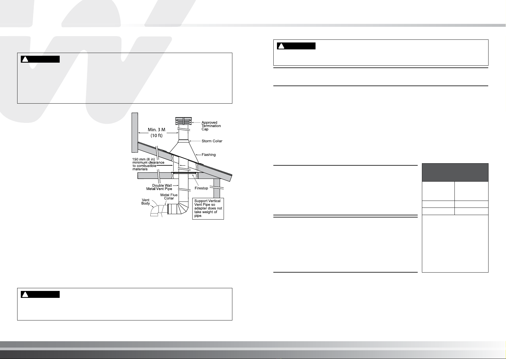
3. Attach the vent pipe to the metal Flue Collar
with sheet-metal screws.
4. Install vent pipe so that it can expand
and contract freely as the temperature
changes. Support the vent pipe according to
applicable codes and the vent manufacturer’s
instructions. Pipe support must allow the vent
pipe free movement out and back, from side
to side, or up and down as necessary, without
putting a strain on the heater or vent body.
Slope horizontal pipe down to condensate
trap at least 2 cm per meter (1/4 in per foot).
Install approved condensate drains at low
points where condensate might collect.
Plumb condensate drains to a drain through
hard piping or high temperature tubing such
as silicone rubber or EPDM rubber – do not
use vinyl or other low temperature tubing.
Follow drain manufacturer’s installation
instructions.
5. Use approved re stop for oor and ceiling
penetrations. Use approved thimble for
wall penetrations. Use an approved roof
ashing, roof jack, or roof thimble for all roof
penetrations. Do not ll the space around the
vent (that is, the clear air space in the thimble
or re stop) with insulation. The roof opening
must be located so that the vent is vertical.
6. Do not run the heater vent into a common
vent with any other appliance.
Risk of re or asphyxiation if vent is not assembled according to manufacturer’s instructions or
if vent parts from different manufacturers are mixed. Vent parts from different manufacturers
ARE NOT interchangeable. Mixing parts from more than one manufacturer may cause leaks
or damage to vent. When assembling a vent, pick one manufacturer and be sure that all vent
parts come from that manufacturer and are specied by the manufacturer for your system.
Follow manufacturer’s instructions, local code requirements and local code standards.
!
WARNING
Fire Hazard. Do not vent the heater directly into a masonry chimney. Installation into a
masonry chimney must use a chimney liner which must meet local code standards and all
local code requirements.
!
WARNING
Risk of fire, carbon monoxide poisoning, or asphyxiation. It is recommended to use a CO
Monitor and Fire Alarm in rooms that contain gas red appliances.
!
WARNING
NOTE
After installation, installer must check for correct and safe operation of the heater.
HORIZONTAL OR VERTICAL VENTING - USING SINGLE-WALL STAINLESS
GAS VENT (See Figures 26, 27 and 28)
Vent the heater either horizontally or vertically using an optional vent adapter of the 150 mm
(6 in) or 102 mm (4 in) special gas approved stainless steel vent pipes. Installation must be in
accordance with AS/NZS 5601.1 and/or local codes and ordinances. The heater, when installed,
must be electrically grounded and bonded in accordance with local codes. Do not use a draft
hood with this heater. Install the vent according to the vent manufacturer’s detailed instructions.
Note: Keep a 150 cm (6 in) minimum clearance between the vent pipe and combustible surfaces.
Follow the vent manufacturer’s instructions and code requirements. Do not place any insulating
materials around the vent or inside the required clear air space surrounding the vent. See Table
8 for maximum permissible vent lengths.
NOTE
The allowable vent runs for each vent pipe diameter are
different and can not be exceeded.
Each 90-degree elbow reduces the maximum horizontal vent
run by 3.6 m (12 feet) and each 45-degree elbow in the vent
run reduces the maximum vent run by 1.8 m (6 feet). See
Table 8 for the maximum vent lengths using 90° elbows.
150 mm (6 in.)
Special Gas Vent
(Vertical or Horizontal)*
No. of 90°
Elbows
Maximum
Length in
Feet (M)
0 11.6 m (38 ft.)
1 8 m (26 ft.)
*Minimum vent length is
0.34M (1 ft.) or in
accordance with vent
manufacturer’s instruction,
and local and national codes.
Horizontal vents 1 m (3 in) or
less in length do not require
a condensate tee, but must
slope down toward the outlet
at 2 cm to the meter (1/4 in / ft.)
to allow condensate to drain.
NOTE
It is recommended vent runs over 5.4 m (18 feet) may need to
be insulated to reduce condensation related problems and/
or the use of a condensate trap in the vent run close to the
heater may be necessary in certain installations such as cold
climates. Horizontal vents 1 m (3 feet) or less in length do not
require a condensate tee. Note: The Turbotemp heater is
suitable for through-the-wall venting.
Flue gases may escape into the dwelling with any cracks or loose joints in the vent pipe,
or improper vent installation. The vent pipe must be of a sealed-seam construction and for
operating temperatures less than 204° C (400°F). Vent pipe construction will be according to
local code standards, approved non-corrosive material, such as stainless steel. A condensate
trap may be needed. The use of “Approved” thimbles, roof jacks and/or side vent terminals are
required; and the proper clearances to combustible materials must be maintained in accordance
with type of vent pipe employed—in the absence of a clearance recommendation by the vent
pipe manufacturer, the requirements of the Uniform Mechanical Code should be met.
See page 14 for ventilation air requirements for the Turbotemp heater.
NOTE: After installation, installer must check for correct and safe operation of the heater.
Figure 25.
– Typical Metal Vent Pipe Installation
(Vertical Venting)
Table 8.


