Watermill PC25DLV User manual

INSTALLATION INSTRUCTIONS
LOW VOLTAGE SHOWER PUMPS
Models PC25DLV PC50DLV
PC55SLV PC70DLV ANHPC60DLV
CUSTOMER SERVICE HELPLINE:
01883 730339
Performance Shower Products

CONTENTS
PLEASE READ THESE INSTRUCTIONS CAREFULLY:
This booklet covers all models in the range;
ensure you follow the appropriate sections.
PAGE
1. GENERAL 1
2. IMPORTANT INSTRUCTIONS 1
3. POSITIONING PUMP 1
4. HOT WATER CYLINDER CONNECTIONS 3
5. COLD WATER SUPPLY 3
6. CONNECTING PUMP 3
7. ELECTRICAL CONNECTIONS 4
8. BEFORE USING 4
9. SERVICING 4
10. FAULT FINDING 5
INSTALLATION CHECK LIST 6
11. TECHNICAL DATA 8
GUARANTEE

Your Watermill Shower Pump has been designed, manufactured and carefully tested in
England.
If correctly installed and not misused, it will give many years of reliable service.
To ensure satisfactory operation, we ask that you read the instructions before
commencing installation. Then car ry out, in sequence, each step as described.
The Important Instructions MUST be followed, otherwise the pump may be damaged
and your guarantee invalidated.
All transformers are fitted with auto resetting thermal cutouts. If the transformer overheats
for any reason, the thermal cutout will switch the pump off. The cutout will automatically turn
on again when the transformer has cooled down.
For the ANHPC60DLV see supplementary Negative Head Instuctions.
If soldering pipe joints do not allow solder flux to come in contact with the plastic parts of
the pump. The plastic will corrode and cause serious leaks.
1. Do not connect pump to water mains pressure. The pump cannot be used with
combination boilers.
2. Select a position for installing the pump which affords easy access for subsequent
servicing and maintenance. This shower pump is fitted with carbon/ceramic mechanical long
life seals which, in some circumstances, can leak. Although this is very unlikely, when
locating the pump, position to mitigate against possible water damage.
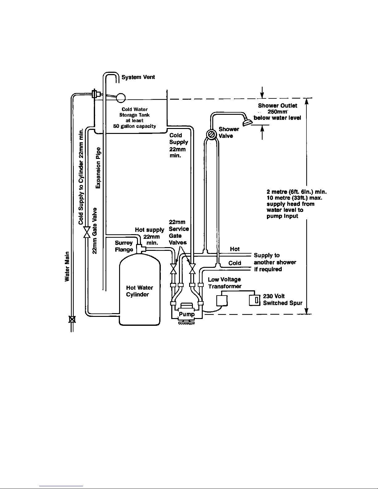
3. The pump must have a supply head of at least 2 metres. If the pump is to be installed
in the loft, the height from the top of the water in the cold water storage tank must be at
least 2 metres above the inlet to the pump.
4. Do not use any jointing compounds such as Boss White, abrasive compounds will
cause the seals to leak.
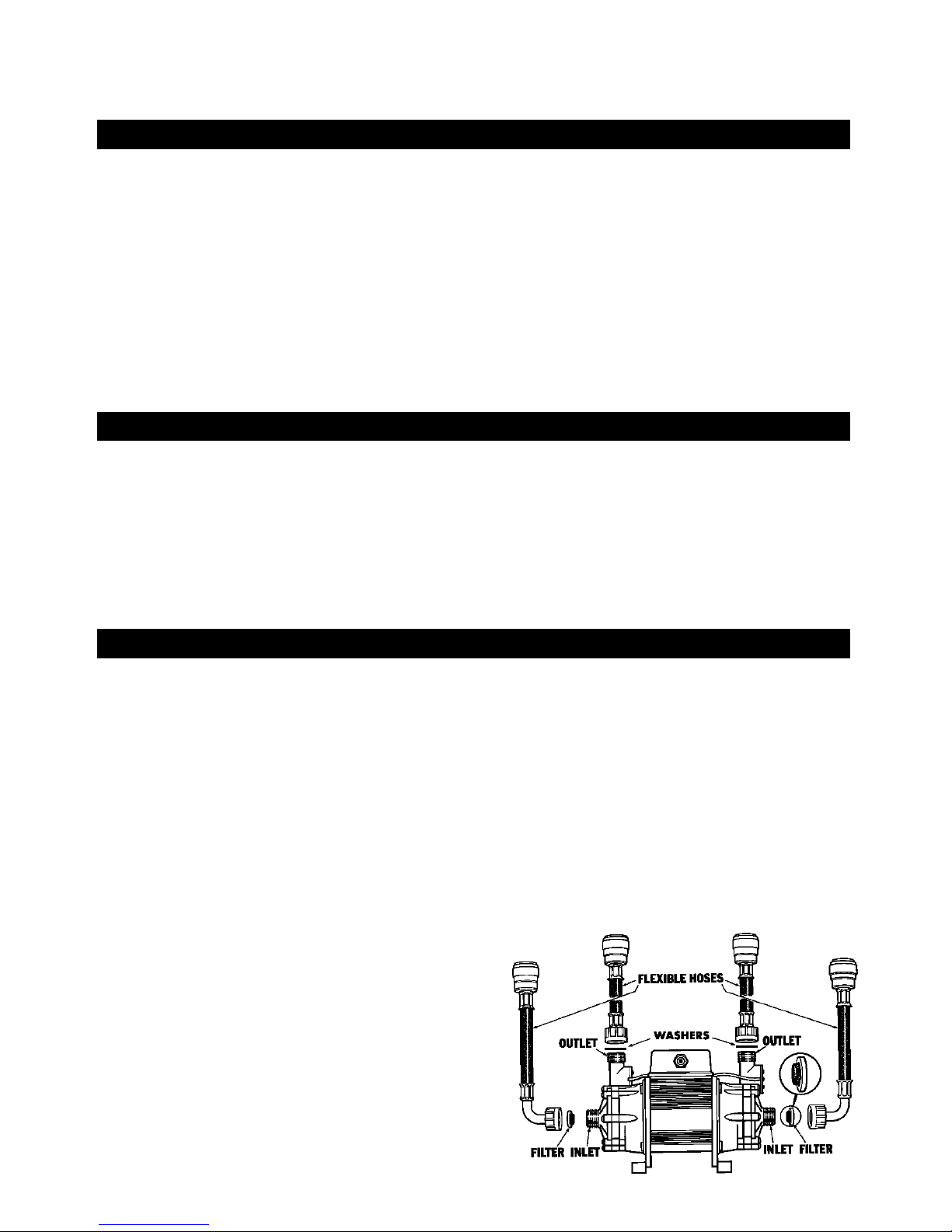
5. The flexible hoses supplied must be used to connect the pump – do not connect any
pipework directly to the pump. The filters must be used on inlet connections.
6. Complete all pipework before making electrical connections – do not let any water into
the electric terminal box.
7. Do not run pump dry– purge with water thoroughly for 5 minutes before running pump.
8. After completing installation, the whole system must be thoroughly tested – operating
both hot and cold at full flow. Also check water temperature stability. Then thoroughly check
each connection is tight and not leaking.
9. Maximum hot water temperature must not exceed 60˚C. The hot water supply to the
pump should be connected from the first outlet from the hot water cylinder expansion pipe.
10. We recommend that all flexible hoses and connections are inspected at least every 6
months. Replace as necessary to prevent leaks.
1. GENERAL
2. IMPORTANT INSTRUCTIONS
3. POSITIONING PUMP
Select a position for installing the pump which affords easy access for future servicing and
maintenance.
Pumps operate better when pumping (pushing) water rather than drawing
(sucking)
water. For this reason, keep the pump as close as possible to the source of both
hot and cold
water. Also keep the pump as low, and the water head as high, as possible.
1

The pump must be mounted horizontally with outlets vertically upwards to ensure correct
operation of the flow switches.
If the pump is to be installed in the loft, there may not be sufficient head to feed the
pump and damage from freezing is possible. (See Note 3 of Section 2).
To reduce noise that may be caused by vibration we recommend the pump be
mounted on a small concrete paving slab approximately 225 x 225mm (9”x 9”) and
40–50mm (11/2” to 2”) thick.
Connect pump and shower system as shown in Fig. 1.
There must be a minimum height between the water level in the cold water storage
cistern and the outlet of the shower handset of 250mm (10”). See Fig. 1.
Negative Head
If the water level of the cold water storage cistern is below
the level of the shower outlet, this
is called a negative head system. To enable the pump to operate it must be either an
Automatic Negative Head pump from the Watermill ANH range or alternatively a Negative
Head Kit needs to be used.
There must also be a minimum height between the water level in the cold water storage
tank and the pump inlet of 2 metres. Suggested location for the pump, if space allows, is on
the floor of the airing cupboard. The area must be well ventilated – the pump must not be
covered by boxes, clothes etc, otherwise the motor will overheat.
2
Fig. 1
(Except
ANHPC60DLY)

5. COLD WATER SUPPLY
DO NOT USE ANY JOINTING COMPOUNDS OR TAPES
Watermill pumps are supplied complete with matching flexible hoses. These hoses must be
used to ensure strain and vibration free, watertight connections.
NOTE: Do not connect metal (Brass/Iron) fittings directly onto pump inlets/outlets. The
threads are 3/4” BSP parallel and are designed for mating only with the flexible hose
connections, nuts and filters/washers supplied. DO NOT USE PTFE TAPE.
For ease of future servicing/filter cleaning, 22mm gate valves are recommended.
The filters supplied should be inserted in the pump inlets only – with the wire dome
towards the pump.
Position pump level on floor, with outlets (flowswitches) vertical. For correct operation
the flowswitches must be vertical.
Position supply pipes and shower hoses accurately so that the pump is not under any
mechanical strain, such as supporting weight of
pipes. Ensure correct alignment to prevent cross
threading and to prevent seals and filters from
leaking.
Line up pipework and fit hoses to pipes
before attaching connectors to pump.
Do not bend hoses as this will cause
restriction of flow.
The plastic nuts should be finger tight plus
1/2 turn. The nuts should be re-tightened after
hot water has been pumped for the first time.
Ensure filters are fitted to the inlets and
washers to outlets.
6. CONNECTING PUMP
4. HOT WATER CYLINDER CONNECTIONS
DO NOT USE ANY JOINTING COMPOUNDS.
The use of a Surrey Flange; see Fig. 1 is recommended to ensure a free flowing supply of “air
free” hot water. Ensure that:
• The controlled hot water temperature is no greater than 60°C.
• Maximise size of pipework to the pump.
Note: All plumbing work should conform to Water Supply (Water Fittings) Regulations
1999.
The hot water feed may be taken directly from the top of the hot water cylinder – but
entrapped air may cause problems.
22mm copper pipe must be used to ensure an adequate flow to the pump. An isolating
gate valve or full bore lever valve is recommended to facilitate pump servicing.
The negative head kit provides for a pneumatic push button and air switch. This enables the
pump to be started by pressing a push button located in the shower area.
DO NOT CONNECT DIRECTLY TO WATER MAINS
DO NOT USE ANY JOINTING COMPOUNDS
The cold water supply to the pump should be connected only from the cold water cistern (do
not connect to the central heating header tank!) see Fig. 1. The tank connector should be
positioned at least 25mm (1”) lower than the cold water feed to the hot water cylinder; see
Fig. 1.An isolating gate valve is recommended to facilitate pump servicing, also 22mm copper
pipe is recommended for connection on the cold water inlet.
3

7. ELECTRICAL CONNECTIONS
THIS IS A LOW VOLTAGE PUMP (USE TRANSFORMER SUPPLIED). DO NOT CONNECT PUMP
DIRECTLY TO 240 VOLT. ELECTRICAL HAZARD WILL RESULT AND THE MOTOR WILL BE
IRREPARABLY DAMAGED.
The low voltage pump has added electrical protection via a safety isolating transformer Fig 1.
For installations where the pump has to be placed in the bathroom (for example under the
bath), we recommend that the safety isolating transformer is placed outside the bathroom or
shower area. DO NOT locate 230–240 volt connections, plugs or switches within the ‘wet’
area in accordance with IEE Regulations.
The low voltage leads from the transformer must be connected to the two terminals
marked ‘T’ in the terminal box. As the supply is AC – the leads can be connected to either
terminal on the pump.
The low voltage pump installation kits are supplied with 3 metres of connecting lead.
The connecting leads between the pump and the isolating transformer can be extended up to
about 15 metres. Use 1.0mm cable.
The safety isolating transformer must be connected to a 230–240 volt 50 Hz supply
with a switched spur fused at 5 amps. The switch must have a double pole disconnection
with a separation gap of at least 3mm. See Fig 1, location.
Ensure compliance with I.E.E. regulations.
Observe colour coding as follows:
Connect BROWN to terminal L (Live)
Connect BLUE to terminal N (Neutral)
For normal operation of the shower, the transformer can be left permanently switched
on – very little power is used when the pump is not running.
Copper pipes should have supplementary earth bonding. Where the earth continuity
has been broken by flexible pipes the pump discharge and suction pipework should be
connected with earthing clamps to BS951 and 4mm earthing wire.
8. BEFORE USING
DO NOT TURN ON THE ELECTRICITY SUPPLY TO THE TRANSFORMER
1. Turn on water supply. Allow system to fill.
2. Immediately inspect for any leaks.
3. Turn on shower mixer valve.
4. Without handset attached to hose – let hose hang into shower tray/bath to gain
maximum possible flow – allow to run for 5 minutes.
5. TURN ON ELECTRICITY supply to pump and repeat paragraph 4.
6. Fix handset to hose.
7. With shower pump operating, carefully inspect again for any leaks at all connections
from both hot and cold feed pipes through to mixer valve and hose connections.
Run hot water for several minutes then re-tighten all hot water connections to pump
and hoses.
8. After completing installation the whole system must be thoroughly tested – operating
both hot and cold at full flow. Then switch off, drain down and clean the filters.
9. The first few times the pump is used, the insulating varnish used on the pump motor
may give off an odour – this is perfectly normal and will diminish with use.
9. SERVICING
1. Regular cleaning and descaling of the handset/shower head is important. The most
common cause of poor shower performance is blockage of the handset or shower head. This
is more likely in hard water areas.
2. If flow from the shower is still below normal it may be necessary to clean the pump
filters. This is very common on initial installation of showers or in new houses where the
jointing compounds, tapes, flux and other debris is being flushed through the system causing
the pump filters to be blocked.
4

10. FAULT FINDING
If the pump doesn’t start, check the following.
1. Electricity supply and fuse (5 Amps rating)
2. Are isolating valves turned on?
3. Has pump run for a long time, causing thermal protection to turn off motor? Wait at
least 2 hours for cut-out to automatically reset.
4. Sufficient water flow to operate the flow switches (0.5 litres per minute) or
approximately 10 inches head of water?
5. Pump filters blocked – this can cause insufficient flow to pump – drain down hot and
cold water supply pipes, clean or replace filters as necessary.
6. Is pump correctly installed with outlets (flowswitches) vertical?
Pump won’t turn of f
1. Is shower mixer valve fully off?
2. Is air entrapped in the shower system?
3. Is flow switch locked in the up (on) position with dirt or some other foreign matter?
Unstable water temperature/noisy pump?
A common cause of poor shower performance and control is air entering the pump, most
commonly from the hot water cylinder.
Air will cause erratic operation of the pump, noise and unstable shower water
temperature.
To reduce the effects of air in the hot water supply:
1. Reduce hot water temperature to 60˚C.
2. Ensure adequate feed to the pump. There should be at least a 2 metre lead (measured
from cold storage water level to input of pump) and all pump supply pipes should be with
22mm gate valves.
3. Fit Surrey flange to ensure good air separation at hot water cylinder.
4. The hot water supply pipes should not have any high sections allowing air traps. If
necessary re-plumb hot water supply pipe, keeping as direct and short as possible.
5. If it is not possible to control the temperature of the hot water a thermostatic blend
valve should be installed. The hot water feed from the cylinder to the pump is disconnected.
The blend valve is connected to both the hot water and cold water supply with the output
connected as the hot water feed to the pump. The thermostatic blend valve can then be
adjusted to ensure the correct 60˚C temperature.
Note: All plumbing work should conform to Water Supply (Water Fittings) Regulations
1999.
In this event turn off service valves, disconnect final connection to the pump, clean
filter, reconnect, turn on water supply.
3. The flexible pump hoses can, dependent on water temperature and mechanical stress,
deteriorate with age. We recommend that all flexible hoses and connections are inspected at
least every 6 months. Replace as necessary to prevent leaks.
5

GUARANTEE OF CORRECT INSTALLATION
NOTE TO CUSTOMER
Your Watermill Shower Pump will only work properly if it has been installed correctly. Ask your
installer to complete the following check list, ensuring it is signed and dated.
NOTE TO INSTALLER
While you are installing this shower pump tick the following “important instructions” to confirm to
both yourself and your customer this shower pump has been correctly installed.
If you need assistance please contact Watermill on the Service Helpline 01883 730339.
The shower pump must be installed in line with current water regulations and I.E.E. Regulations.
When the installation is completed please sign and date the Guarantee of Correct Installation and
then pass to customer to keep.
IMPORTANT INSTRUCTIONS
1. Do not connect shower pump to water mains pressure. The shower pump cannot
be used with combination boilers.
2. The pump should have a supply head of at least 2 metres/6 ft. That is, the level
of the water in the tank must be this distance above the pump.
3. a) Do not use any jointing compounds: these compounds will cause seals to leak.
b) If soldering pipe joints do NOT allow ANY solder flux to come in contact
with plastic parts of the shower pump. The plastic will be corroded and will
cause serious leaks.
4. Flexible hoses must be used to connect the pump – do not connect any
pipework directly to the pump.
5. Complete all pipework before making electrical connections.
6. Do not run pump dry – purge with water thoroughly for 5 minutes before
running pump.
7. Maximum hot water temperature must not exceed 60˚C (130˚F). The hot
water supply to the shower pump must NOT be connected to the hot water
cylinder expansion pipe.
8. Please ensure that the installer has explained the correct operation of
the shower pump.
Signed: Date:
Company:
If the shower pump installation does not conform to these instructions, the shower pump
guarantee may be invalidated and the cost of any “on site” visits by the Watermill Service
Department will be charged for.
6

7

11. TECHNICAL DATA
PC25DLV PC50DLV PC55SLV PC70DLV
ELECTRICAL
Transformer Input 230V/50Hz 230V/50Hz 230V/50Hz 230V/50Hz
Transformer Output 31V 34V 38V 40V
Power Consumption 150W 220W 110W 380W
Rating S2 25min S1 Continuous S2 75min S1 Continuous
Motor Permanent Magnet Low Voltage dc
MECHANICAL
Inlet Head (min-max) 2-10m 2-10m 2-10m 2-10m
Max Developed Pump Head 8m 13m 17m 20m
Max Working Pressure 3 bar 3 bar 3 bar 3 bar
Approx. Starting Flow Rate 0.5lpm 0.5lpm 0.5lpm 0.5lpm
DIMENSIONS
Length (mm) 275 275 225 285
Width (mm) 120 120 120 120
Height (mm) 185 185 185 185
NOISE
The sound pressure level 1m from the pump is less than 70dbA
For ANHPC60DLV See supplementary instructions
8
WATERMILL PRODUCTS LTD
WATERMILL HOUSE, FAIRVIEW INDUSTRIAL ESTATE, HOLLAND ROAD, HURST GREEN, OXTED, SURREY RH8 9BD
CUSTOMER SERVICE HELPLINE TEL: 01883 730339
ML 305 02/04 Printed in England

Watermill Products Ltd Guarantee Registration Card
Product serial number
Name
Address
Post Code
Telephone number E-mail
Date of purchase Product type
Purchased from
Installed by
A COPY OF THE ORIGINAL PURCHASE INVOICE MUST BE ATTACHED
WATERMILL PRODUCTS LTD GUARANTEE JANUARY 2004
Watermill Products Ltd. guarantee the parts and workmanship of this product for a period of
two years from the date of initial purchase, provided that:
The product is installed and operated in accordance with our instructions and has not
been damaged or abused.
The guarantee registration card is completed and returned within ten days of purchase
accompanied by a copy of the original invoice (proof of purchase). We will acknowledge
receipt of the guarantee registration card within ten days. It is this guarantee
acknowledgement that acts as your two year guarantee and must be kept in a safe
place and produced in the event of a claim under the terms of this guarantee. If this
acknowledgement cannot be produced, the guarantee reverts to two years from date of
manufacture.
The information on the guarantee registration card is purely for the use of Watermill Products
Ltd. in connection with the guarantee of the product. The information will not be divulged to
third parties or used by Watermill for any other marketing activities.
The guarantee is limited to product repair or replacement only.
This guarantee does not affect your statutory rights.

GUARANTEE CLAIM PROCEDURE
If you believe the product is not operating correctly, phone the helpline number 01883
730339. Most problems with pumps can be eradicated by adjustments to the pump or
installation. Please have to hand your:- Guarantee acknowledgement. If the product has not
as yet been registered, or the acknowledgement has been mislaid please have to hand your:-
Proof of purchase, Pump type (to be found on top label), Pump serial number (to be found
on top label).
DO NOT REMOVE THE PUMP FROM ITS INSTALLATION AS THIS WILL INVALIDATE THE
GUARANTEE.
A large percentage of pumps removed from site and returned to us work perfectly when
tested in our laboratory. This makes it very difficult for us to help you solve the problem long
term. Sometimes the product is just not suitable for the application. It helps us to help you
if we can obtain details of the application.
It is also very useful to have digital photographs of the installation e--mailed to
service@watermillshowers.co.uk prior to contacting us. These photographs should show as
much of the installation as possible, in particular:- The pump and hoses, the connection to
the cylinder, the connection to the cold water tank, the top label on the pump, the proof of
purchase.
If an engineer’s site visit call is required there must be an adult on site during the visit.
Site visits to products malfunctioning that are covered by the terms of this guarantee will
be provided free of charge. Site visits to products outside the terms of this guarantee will
be on a chargeable basis for parts and labour and must be paid for at the time of the site
visit.
Watermill Products Limited
Watermill House
Fairview Industrial Estate
Holland Road
Hurst Green
Oxted
Surrey RH8 9BD
Please Return to:
This manual suits for next models
4
Table of contents
Other Watermill Water Pump manuals
Popular Water Pump manuals by other brands

Parker
Parker HP2 Series Service Procedure

FPS
FPS VR Series owner's manual

HAMMELMANN
HAMMELMANN HDP 502 / S 1100-50 operating instructions

Polaris
Polaris TBM 150 MH Series Installation, operation and maintenance manual

Wilo
Wilo American-Marsh Pumps 482 EGB Series Installation and operating manual

Sibata
Sibata LVS-30 Operation manual

Zodiac
Zodiac VS FloPro E3 Series Installation and operation manual

ATURIA
ATURIA TK instruction manual

NPC
NPC Betta FLO BMLS-M Installation, operation & maintenance instructions

Xylem
Xylem FLOJET R3521 Series instruction manual

Orion
Orion 21200 manual

Judo
Judo PROMI-PLUS JPM+ 3/4 Installation and operating instructions