Waters 1500-Series Manual

Waters 1500-Series
HPLC Pump and Options
Operator’s Guide
715002013IVD /Revision C
Copyright © Waters Corporation 2014
All rights reserved

ii
Copyright notice
© 2014 WATERS CORPORATION. PRINTED IN THE UNITED STATES OF
AMERICA AND IN IRELAND. ALL RIGHTS RESERVED. THIS
DOCUMENT OR PARTS THEREOF MAY NOT BE REPRODUCED IN ANY
FORM WITHOUT THE WRITTEN PERMISSION OF THE PUBLISHER.
The information in this document is subject to change without notice and
should not be construed as a commitment by Waters Corporation. Waters
Corporation assumes no responsibility for any errors that may appear in this
document. This document is believed to be complete and accurate at the time
of publication. In no event shall Waters Corporation be liable for incidental or
consequential damages in connection with, or arising from, its use.
Trademarks
Waters is a registered trademark of Waters Corporation, and Breeze,
Empower, LAC/E, SAT/IN, and “THE SCIENCE OF WHAT’S POSSIBLE.”
are trademarks of Waters Corporation.
Luer is a registered trademark of Becton, Dickinson, and Company.
PharMed and Tygon are registered trademarks of Saint-Gobain Performance
Plastics Corporation.
Tefzel is a registered trademark of duPont de Nemours and Company, Inc.
TORX is a registered trademark of Acument Global Technologies.
Other registered trademarks or trademarks are the sole property of their
owners.

iii
Customer comments
Waters’ Technical Communications department invites you to tell us of any
errors you encounter in this document or to suggest ideas for otherwise
improving it. Please help us better understand what you expect from our
documentation so that we can continuously improve its accuracy and
usability.
We seriously consider every customer comment we receive. You can reach us
Contacting Waters
Contact Waters®with enhancement requests or technical questions regarding
the use, transportation, removal, or disposal of any Waters product. You can
reach us via the Internet, telephone, or conventional mail.
Safety considerations
Some reagents and samples used with Waters instruments and devices can
pose chemical, biological, and radiological hazards. You must know the
potentially hazardous effects of all substances you work with. Always follow
Waters contact information
Contacting medium Information
Internet The Waters Web site includes contact
information for Waters locations worldwide.
Visit www.waters.com.
Telephone and fax From the USA or Canada, phone 800
252-HPLC, or fax 508 872 1990.
For other locations worldwide, phone and fax
numbers appear in the Waters Web site.
Conventional mail Waters Corporation
34 Maple Street
Milford, MA 01757
USA

iv
Good Laboratory Practice, and consult your organization’s safety
representative for guidance.
Considerations specific to the 1500-Series HPLC pumps and
column heater
Radiation hazard
The equipment does not emit any type of hazardous radiation. It emits a
minimum amount of electromagnetic radiation that is within the limits of
applicable emissions standards (EN61326).
Protective grounding
The pump and column heater requires protective grounding for operation. The
three-conductor electrical cord that supplies power also grounds the device.
This power cord is approved by a nationally recognized testing laboratory (UL
or ETL). It must comprise three, 18-gauge, insulated conductors and be rated
for 300 V.
Back siphoning and draining
Check valves in the fluid pump, installed ahead of the column heater, prevent
the back-siphoning of fluids.
Drainage systems are installed in this equipment. Drip trays inside the pump
and column heater units catch any fluid from leaks or spills. These trays are
connected to external drains on the bottom of the units. Tubing connected to
this drain routes the fluid into an appropriate waste container.
Hazardous waste
During standard operation, this device does not produce any byproducts or
waste. Any waste resulting from a leak or spill is channeled into the drain
located on the underside of the device. Tubing connected to this drain directs
the flow to an appropriate waste container.
Equipment repair or disposal
Direct questions regarding repair or disposal to Waters. Waters carries out
equipment disposal in Europe according to the WEEE directive specific to the

v
country. Waters also accommodates any special requirements for locations
outside of Europe.
Safety advisories
Consult Appendix A for a comprehensive list of warning and caution
advisories.
Operating the Waters 1500-Series HPLC pump and
options
When operating these pumps and options, follow standard quality-control
(QC) procedures and the guidelines presented in this section.

vi
Applicable symbols
Audience and purpose
This guide is intended for use by individuals who need to install, maintain,
and/or troubleshoot the Waters 1500-Series HPLC Pump and options. You
should be familiar with HPLC terms, practices, and basic HPLC system
operations such as connecting tubing.
Intended use of the Waters 1500-Series HPLC pump and options
Use the Waters 1525, 1525µ, and 1525EF HPLC pumps and the optional
1500-Series Column Heater and its options to deliver a precisely controlled
amount of solvent to a column, maintaining a consistent and reproducible
mobile phase composition. The Waters 1500-Series HPLC pump and options
are for research use only.
Symbol Definition
Manufacturer
Authorized representative of the European
Community
Confirms that a manufactured product complies
with all applicable European Community
directives
Australia C-Tick EMC Compliant
Confirms that a manufactured product complies
with all applicable United States and Canadian
safety requirements
Consult instructions for use

vii
Calibrating
To calibrate LC systems, follow acceptable calibration methods using at least
five standards to generate a standard curve. The concentration range for
standards should include the entire range of QC samples, typical specimens,
and atypical specimens.
When calibrating mass spectrometers, consult the calibration section of the
operator’s guide for the instrument you are calibrating. In cases where an
overview and maintenance guide, not operator’s guide, accompanies the
instrument, consult the instrument’s online Help system for calibration
instructions.
Quality-control
Routinely run three QC samples that represent subnormal, normal, and
above-normal levels of a compound. Ensure that QC sample results fall within
an acceptable range, and evaluate precision from day to day and run to run.
Data collected when QC samples are out of range might not be valid. Do not
report these data until you are certain that the instrument performs
satisfactorily.
When analyzing samples from a complex matrix such as soil, tissue,
serum/plasma, whole blood, and other sources, note that the matrix
components can adversely affect LC/MS results, enhancing or suppressing
ionization. To minimize these matrix effects, Waters recommends you adopt
the following measures:
• Prior to the instrumental analysis, use appropriate sample
pretreatment such as protein precipitation, liquid/liquid extraction
(LLE), or solid phase extraction (SPE) to remove matrix interferences.
• Whenever possible, verify method accuracy and precision using
matrix-matched calibrators and QC samples.
• Use one or more internal standard compounds, preferably isotopically
labeled analytes.
viii
ISM classification
ISM Classification: ISM Group 1 Class B
This classification has been assigned in accordance with CISPR 11 Industrial
Scientific and Medical (ISM) instruments requirements. Group 1 products
apply to intentionally generated and/or used conductively coupled
radio-frequency energy that is necessary for the internal functioning of the
equipment. Class B products are suitable for use in both commercial and
residential locations and can be directly connected to a low voltage,
power-supply network.
EC authorized representative
Waters Corporation
Stamford Avenue
Altrincham Road
Wilmslow SK9 4AX
United Kingdom
Telephone: +44-161-946-2400
Fax: +44-161-946-2480
Contact: Quality manager

Table of Contents ix
Copyright notice ................................................................................................... ii
Trademarks ............................................................................................................ ii
Customer comments ............................................................................................ iii
Contacting Waters ............................................................................................... iii
Safety considerations .......................................................................................... iii
Considerations specific to the 1500-Series HPLC pumps and column heater iv
Safety advisories.................................................................................................. v
Operating the Waters 1500-Series HPLC pump and options ...................... v
Applicable symbols .............................................................................................. v
Audience and purpose.......................................................................................... v
Intended use of the Waters 1500-Series HPLC pump and options.................. vi
Calibrating .......................................................................................................... vi
Quality-control .................................................................................................... vi
ISM classification ................................................................................................ vii
ISM Classification: ISM Group 1 Class B ....................................................... vii
EC authorized representative ........................................................................ viii
1 Introduction ............................................................................................ 1-1
HPLC pump operating principles ................................................................. 1-2
Isocratic and gradient LC system operation .................................................. 1-2
Effects of dissolved oxygen on the mobile phase............................................ 1-3
Using in-line degassing to remove gases from eluents.................................. 1-4
Overview of the 1500-series HPLC pumps .................................................. 1-5
Fluid-handling components ........................................................................... 1-7
Electronic components .................................................................................. 1-12
Pump control ................................................................................................... 1-13
Ethernet configuration .................................................................................. 1-14
Table of Contents

x Table of Contents
IEEE-488 configuration................................................................................. 1-14
Options and accessories ................................................................................ 1-15
1500-series column heater............................................................................. 1-15
Integral vacuum degasser ............................................................................. 1-15
Automated plunger seal wash....................................................................... 1-16
Manual injector.............................................................................................. 1-16
Ethernet communications kit........................................................................ 1-16
Gradient mixers ............................................................................................. 1-17
2 Installing the HPLC Pump ................................................................... 2-1
Site requirements ............................................................................................. 2-2
Unpacking ........................................................................................................... 2-3
Connecting power and signal cables ............................................................ 2-4
Connecting the power supply .......................................................................... 2-5
Making ethernet connections.......................................................................... 2-5
Making IEEE-488 connections........................................................................ 2-6
Setting the IEEE-488 address......................................................................... 2-9
Connecting pump inlet and outlet lines .................................................... 2-11
Connecting the eluent supply........................................................................ 2-11
Connecting the pump outlet.......................................................................... 2-14
Connecting fluid waste lines ......................................................................... 2-16
3 Installing Options and Accessories ................................................... 3-1
Installing the 1500-series column heater .................................................... 3-2
Installing a manual injector ........................................................................... 3-4
Connecting to the column or column heater................................................... 3-5
Connecting the inject start signal (for manual injector)................................ 3-5
Installing different eluent mixers ................................................................. 3-8
Installing the integral vacuum degasser ................................................... 3-14
Connecting tubing to the degasser inlet and outlet..................................... 3-15
Installing the degasser vent line................................................................... 3-16
Using the degasser......................................................................................... 3-17

Table of Contents xi
Installing the plunger seal wash system ................................................... 3-17
Preparing the instrument ............................................................................. 3-18
Removing pump head components................................................................ 3-19
Installing head support components (1515/1525 pump only)...................... 3-21
Installing head support components (1525EF pump only).......................... 3-25
Installing head components (1525µ pump only) .......................................... 3-27
Installing the solenoid ................................................................................... 3-29
Installing seal wash tubing ........................................................................... 3-31
Using the seal wash system .......................................................................... 3-33
4 Preparing for Operation ...................................................................... 4-1
Startup and initial preparation ..................................................................... 4-2
Powering-on the pump..................................................................................... 4-2
Pump preparation recommendations ............................................................. 4-2
Dry priming the pump..................................................................................... 4-4
Operating with the integral vacuum degasser............................................... 4-5
Operating with the plunger seal wash system............................................... 4-8
Maximum flow rates for 1500-series pumps ................................................ 4-10
Preparing for Breeze 2 operation ............................................................... 4-10
Priming and purging the pump via Breeze 2 control................................... 4-11
Purging the flow path via Breeze 2 control .................................................. 4-12
Equilibrating the system via Breeze 2 control............................................. 4-13
Preparing for Empower 2 operation .......................................................... 4-15
Priming and purging the pump via Empower 2 control .............................. 4-15
Purging the flow path via Empower 2 control.............................................. 4-16
Equilibrating the system via Empower 2 control ........................................ 4-18
Preparing for MassLynx operation ............................................................ 4-19
Priming and purging the pump via MassLynx control................................ 4-19
Purging the flow path via MassLynx control ............................................... 4-20
Equilibrating the system via MassLynx control .......................................... 4-22
Powering off the pump .................................................................................. 4-23
5 Maintaining the HPLC Pump .............................................................. 5-1

xii Table of Contents
Maintenance considerations .......................................................................... 5-2
Safety and handling......................................................................................... 5-2
Proper operating procedures ........................................................................... 5-2
Spare parts....................................................................................................... 5-2
Contacting Waters Technical Service............................................................. 5-2
Performing pump diagnostic tests ............................................................... 5-3
Retention time stability test ........................................................................... 5-3
Ramp-and-decay test ....................................................................................... 5-3
Replacing and cleaning plunger seals and plungers ................................ 5-6
Preparing for plunger seal replacement ......................................................... 5-6
Cleaning and replacing the plungers.............................................................. 5-9
Replacing check valves .................................................................................. 5-14
Replacing 1515/1525 check valves ................................................................ 5-15
Replacing 1525EF check valves .................................................................... 5-17
Replacing 1525µ check valves ....................................................................... 5-19
Replacing a draw-off valve ........................................................................... 5-22
Removing the draw-off valve......................................................................... 5-23
Installing a draw-off valve ............................................................................ 5-24
Replacing fuses ................................................................................................ 5-25
Replacing the rear panel fuses...................................................................... 5-26
6 Troubleshooting ..................................................................................... 6-1
Troubleshooting pump problems .................................................................. 6-2
Identifying and correcting noises ................................................................. 6-8
Identifying chromatographic problems ...................................................... 6-9
A Safety Advisories .................................................................................. A-1
Warning symbols ............................................................................................... A-2
Task-specific hazard warnings........................................................................ A-2
Specific warnings ............................................................................................. A-3
Caution symbol .................................................................................................. A-5

Table of Contents xiii
Warnings that apply to all Waters instruments ......................................... A-6
Electrical and handling symbols ................................................................. A-12
Electrical symbols .......................................................................................... A-12
Handling symbols .......................................................................................... A-13
B Specifications ........................................................................................ B-1
C Solvent Considerations ....................................................................... C-1
Introduction ...................................................................................................... C-2
Clean solvents .................................................................................................. C-2
Solvent quality ................................................................................................. C-2
Preparation checklist....................................................................................... C-2
Water ................................................................................................................ C-2
Buffers .............................................................................................................. C-3
Tetrahydrofuran (THF) ................................................................................... C-3
Solvent compatibility ...................................................................................... C-3
Solvents to avoid .............................................................................................. C-3
Solvents to use ................................................................................................. C-3
Solvent miscibility ........................................................................................... C-6
How to use miscibility numbers (M-numbers) ............................................... C-8
Buffered solvents ............................................................................................. C-8
Head height ....................................................................................................... C-9
Solvent viscosity ............................................................................................... C-9
Mobile phase solvent degassing ................................................................... C-9
Gas solubility ................................................................................................... C-9
Eluent degassing methods............................................................................. C-10
Wavelength selection .................................................................................... C-12
UV cutoffs for common solvents.................................................................... C-12
Mixed mobile phases...................................................................................... C-13
Refractive indices of common solvents ......................................................... C-14
Index ..................................................................................................... Index-1

xiv Table of Contents

1-1
1Introduction
This chapter describes key operating principles, pump components, data
control configurations, and available options for the 1500-series HPLC
pumps.
Contents
Topic Page
HPLC pump operating principles 1-2
Overview of the 1500-series HPLC pumps 1-5
Fluid-handling components 1-7
Electronic components 1-12
Pump control 1-13
Options and accessories 1-15

1-2 Introduction
HPLC pump operating principles
This section describes these topics:
• Isocratic and gradient LC system operation
• Effects of dissolved oxygen in the mobile phase
• Removing gases from eluents using in-line degassing
Isocratic and gradient LC system operation
Two basic elution modes are used in HPLC: isocratic elution and gradient
elution.
In isocratic elution, the mobile phase, either a pure solvent or a mixture,
remains the same throughout the run. For LC system operation, a single
pump system, such as the 1515 isocratic pump, delivers a controlled amount of
solvent into the column to maintain consistent and reproducible mobile phase
composition.
In gradient elution, the mobile phase composition changes during the
separation. This mode is useful for samples that contain compounds that span
a wide range of chromatographic polarity. As the separation proceeds, the
elution strength of the mobile phase is increased to elute the more strongly
retained sample components.
In the simplest configuration, there are two bottles of solvent and two pumps,
the case when using a 1525 binary pump. The speed of each pump is managed
by the gradient controller to deliver more or less of each solvent over the
course of the separation. The two streams are combined using a mixer to
create the actual mobile phase composition that is delivered to the column
over time. At the beginning, the mobile phase contains a higher proportion of
the weaker solvent (solvent A). Over time, the proportion of the stronger
solvent (solvent B) is increased according to a predetermined timetable.
Because the mixer is downstream of the pumps, the gradient is created under
high pressure.
Other HPLC systems, such as Waters Alliance systems, are designed to mix
multiple streams of solvents under low pressure, ahead of a single pump. A
gradient proportioning valve selects from the multiple solvent bottles,
changing the strength of the mobile phase over time.

HPLC pump operating principles 1-3
Effects of dissolved oxygen on the mobile phase
Dissolved oxygen in the mobile phase can be of special concern. It can under
certain circumstances interfere with the detection of analytes by UV/Vis,
fluorescence, or electrochemical detectors.1
Effects on UV/Vis detectors
Oxygen can form UV-absorbing complexes with solvents such as methanol or
tetrahydrofuran (THF). These complexes increase the background
absorbance, especially at lower wavelengths. This leads to a small decrease in
sensitivity of detection. More importantly, however, they cause baseline shifts,
or ghost peaks, during gradient separations. Also, a change in the dissolved
oxygen level over time, especially when it results from reabsorption of
ambient gases following an offline degassing technique, causes baseline drift
and irregularity.
Removing dissolved oxygen to a reproducible level greatly enhances the
performance of UV/Vis detectors, especially below 254 nm and in gradient
systems. It also improves sensitivity in certain fluorescence detection
applications.
Effects on fluorescence detectors
For certain analytes at certain wavelengths, oxygen, under certain mobile
phase conditions, can quench fluorescence response. Aromatic hydrocarbons,
aliphatic aldehydes, and ketones are particularly susceptible to quenching,
and decreases in sensitivity of 95% are possible.
Effects on electrochemical detectors
Oxygen can interfere with various electrochemical detection techniques,
particularly reductive electrochemistry.
Effects on refractive index detectors
Refractive index detectors are sensitive to changes in solvent density.
Removing dissolved gases to a consistent level enhances the performance of
refractive index detectors, reducing baseline drift and irregularity.
1. Rollie, Mae E., Gabor Patonay, Isaiah M. Warner, Ind. Eng. Chem. Res., 1987, 26, 1–6.

1-4 Introduction
Using in-line degassing to remove gases from eluents
In-line methods of degassing operate within the chromatographic fluid path.
The 1500-series integral vacuum degasser uses this approach. Because
degassing occurs close to the pump, this method minimizes reabsorption of
ambient gas into the eluent.
The flow rate of eluent through an in-line degasser determines the efficiency
of the degassing. At low flow rates, most of the dissolved gas is removed as the
eluent passes through the vacuum chambers. At higher flow rates, lesser
amounts of gas per unit volume of eluent are removed.
Degassing efficiency
The flow rate of eluent through the degasser determines the efficiency with
which the degasser removes gases. As the flow rate increases, the time
available to remove dissolved gases from the eluent lessens. The following
table shows the relationship between the flow rate of an eluent (water) and
the concentration of a gas (oxygen) dissolved in the eluent.
Degasser operating principles
The degasser operates according to Henry’s Law, removing dissolved gases
from the eluent. Henry’s Law states that the mole fraction of a gas dissolved
in a liquid is proportional to the partial pressure of that gas in the vapor phase
above the liquid. If the partial pressure of a gas on the surface of the liquid is
reduced–by evacuation, for example–then a proportional amount of that gas
comes out of solution.
The degasser uses a gas-permeable polymer membrane channel to carry the
eluent through the vacuum chamber. When the eluent enters the vacuum
chamber, the vacuum creates a large differential in gas concentration across
the membrane. This differential accelerates the rate at which the dissolved
gases diffuse through the polymer membrane into the vacuum chamber. The
Effect of flow rate on final dissolved gas concentration
Flow rate
(mL/min)
Final oxygen
concentration (ppm)
1≤1
2≤1.3
5≤2.3
Overview of the 1500-series HPLC pumps 1-5
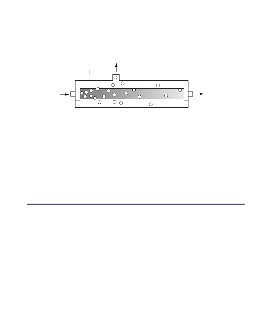
gases are then carried away by the vacuum pump. The following figure is a
simplified schematic diagram of the vacuum chamber.
Vacuum chamber schematic
The longer the eluent is exposed to the vacuum, the more dissolved gases are
removed. Two factors affect the amount of time the eluent is exposed to the
vacuum:
• Flow rate – A lower flow rate increases the amount of time the eluent is
exposed to the vacuum. “Degassing efficiency” on page 1-4, addresses the
effect of different flow rates on the concentration of remaining gas.
• Surface area of degassing membrane – The length of the degassing
membrane is fixed in each vacuum chamber.
Overview of the 1500-series HPLC pumps
The 1500-series HPLC pumps combine the most important aspects of eluent
delivery for HPLC: high precision, reliability, and smooth eluent flow. All
pumps perform their intended functions equally well:
• The 1515 isocratic HPLC pump is designed for precise isocratic
analyses, with flow rates up to 10 mL/minute.
• The 1525 binary HPLC pump achieves reproducible, binary gradient
delivery, with exceptionally smooth concurrent-stream blending with
flow rates of up to 10 mL/minute.
Degassed
eluent out
Gas out
(to vacuum pump)
Vacuum chamberEluent channel
More gas
in solution
Less gas
in solution
Gas-saturated
eluent In

1-6 Introduction
• The 1525EF (Extended Flow) binary HPLC pump is a field-upgrade of
the standard 1525 binary pump designed for increased flow rates of up
to 22.5 mL/minute.
• The 1525µ binary HPLC pump is designed for precise, reproducible
gradient delivery at low flow rates up to 5 mL/minute.
In an HPLC system, the 1500-series pump is controlled by Waters Breeze™ 2,
Empower™ 2, or MassLynx™ data control software (see page 1-13).
Tip: For detailed information about specific data control software versions and
requirements, refer to the release notes for the Waters 1500-series HPLC
pumps.
The microprocessor-controlled stepper motor and noncircular gears of each
pump ensures smooth and precise flow regardless of backpressure, flow-rate
setting, or eluent compressibility.
These optional components are available for the 1500-series pump to suit your
HPLC applications and site requirements:
• 1500-series column heater – Enables preheating of fluids passing
through chromatographic columns.
• Integral vacuum degasser – Provides HPLC pumps with an automatic,
continuous method of removing dissolved gasses from mobile phases.
The degasser is standard on the 1525µ pump and is available as an
option on the 1515 isocratic pump and 1525 and 1525EF binary pumps.
• Plunger seal wash system – Extends the life of pump seals by
lubricating the plunger and flushing away solvent or dried salts forced
past the plunger seal from the high-pressure side of each piston
chamber.
• Manual injector – For use in place of an autosampler to provide precise
manual control of HPLC sample injections.
For more details, see page 1-15.
The following figure shows a 1525 binary pump with an optional column
heater.
This manual suits for next models
3
Table of contents
Other Waters Water Pump manuals


Popular Water Pump manuals by other brands


Sealey
Sealey SWP30 instructions

stellar labs
stellar labs HESC Series Installation, operation and maintenance manual

SKF
SKF FB Assembly instructions

Homa
Homa TCV 408 Series Original instruction manual

OLIJU
OLIJU Dreno R 30 Series Installation and operation instructions

ProMinent
ProMinent DULCO Trans 32/700 PVDF Assembly and operating instructions