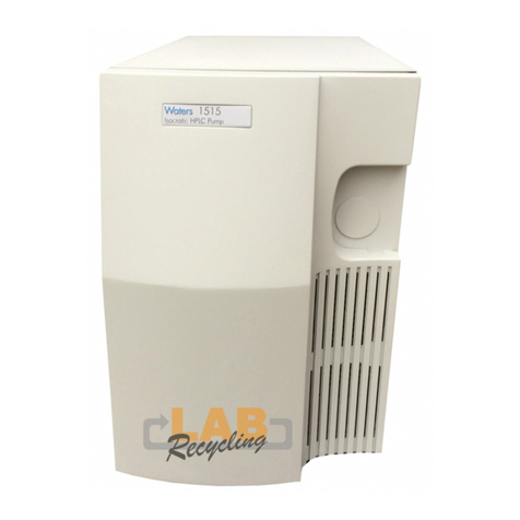
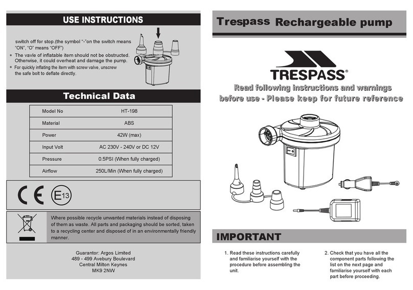
Waters 515 HPLC Manual

515 HPLC Pump
Operator’s Guide
WAT068980/Revision 5
Copyright © Waters Corporation 2016
All rights reserved

ii
Copyright notice
© 2010-2016 WATERS CORPORATION. PRINTED IN THE UNITED
STATES OF AMERICA AND IN IRELAND. ALL RIGHTS RESERVED. THIS
DOCUMENT OR PARTS THEREOF MAY NOT BE REPRODUCED IN ANY
FORM WITHOUT THE WRITTEN PERMISSION OF THE PUBLISHER.
The information in this document is subject to change without notice and
should not be construed as a commitment by Waters Corporation. Waters
Corporation assumes no responsibility for any errors that may appear in this
document. This document is believed to be complete and accurate at the time
of publication. In no event shall Waters Corporation be liable for incidental or
consequential damages in connection with, or arising from, its use.
Trademarks
Waters, Millennium, and “THE SCIENCE OF WHAT’S POSSIBLE.”are
registered trademarks of Waters Corporation, and ExpertEase is a trademark
of Waters Corporation.
Other registered trademarks or trademarks are the sole property of their
owners.

iii
Customer comments
Waters’ Technical Communications department invites you to tell us of any
errors you encounter in this document or to suggest ideas for otherwise
improving it. Please help us better understand what you expect from our
documentation so that we can continuously improve its accuracy and
usability.
We seriously consider every customer comment we receive. You can reach us
Contacting Waters
Contact Waters®with enhancement requests or technical questions regarding
the use, transportation, removal, or disposal of any Waters product. You can
reach us via the Internet, telephone, or conventional mail.
Waters contact information
Contacting medium Information
Internet The Waters Web site includes contact
information for Waters locations worldwide.
Visit www.waters.com.
Telephone and fax From the USA or Canada, phone 800
252-HPLC, or fax 508 872 1990.
For other locations worldwide, phone and fax
numbers appear in the Waters Web site.
Conventional mail Waters Corporation
34 Maple Street
Milford, MA 01757
USA

iv
Safety considerations
Some reagents and samples used with Waters instruments and devices can
pose chemical, biological, and radiological hazards. You must know the
potentially hazardous effects of all substances you work with. Always follow
Good Laboratory Practice, and consult your organization’s safety
representative for guidance.
Considerations specific to the 515 HPLC Pump
Note: When you use the instrument, follow generally accepted procedures for
quality control and methods development.
If you observe a change in the retention of a particular compound, in the
resolution between two compounds, or in peak shape, immediately determine
the reason for the changes. Until you determine the cause of a change, do not
rely on the separation results.
Note: The Installation Category (Overvoltage Category) for this instrument is
Level II. The Level II Category pertains to equipment that receives its
electrical power from a local level, such as an electrical wall outlet.
Safety advisories
Consult Appendix A for a comprehensive list of warning and caution
advisories.

v
Operating this instrument
When operating this instrument, follow standard quality-control (QC)
procedures and the guidelines presented in this section.
Applicable symbols
Audience and purpose
This guide is intended for personnel who install, operate, and maintain the
Waters 515 HPLC Pump.
Intended use of the Waters 515 HPLC Pump
The Waters 515 HPLC Pump is for research use only.
Calibrating
To calibrate LC systems, follow acceptable calibration methods using at least
five standards to generate a standard curve. The concentration range for
Symbol Definition
Manufacturer location
Authorized representative of the European
Community
Confirms that a manufactured product complies
with all applicable European Community
directives
Australia C-Tick EMC Compliant
Confirms that a manufactured product complies
with all applicable United States and Canadian
safety requirements
Consult instructions for use

vi
standards should include the entire range of QC samples, typical specimens,
and atypical specimens.
When calibrating mass spectrometers, consult the calibration section of the
operator’s guide for the instrument you are calibrating. In cases where an
overview and maintenance guide, not operator’s guide, accompanies the
instrument, consult the instrument’s online Help system for calibration
instructions.
Quality-control
Routinely run three QC samples that represent subnormal, normal, and
above-normal levels of a compound. Ensure that QC sample results fall within
an acceptable range, and evaluate precision from day to day and run to run.
Data collected when QC samples are out of range might not be valid. Do not
report these data until you are certain that the instrument performs
satisfactorily.
ISM classification
ISM Classification: ISM Group 1 Class B
This classification has been assigned in accordance with CISPR 11 Industrial
Scientific and Medical (ISM) instruments requirements. Group 1 products
apply to intentionally generated and/or used conductively coupled
radio-frequency energy that is necessary for the internal functioning of the
equipment. Class B products are suitable for use in both commercial and
residential locations and can be directly connected to a low voltage,
power-supply network.

vii
EC authorized representative
Waters Corporation
Stamford Avenue
Altrincham Road
Wilmslow SK9 4AX UK
Telephone: +44-161-946-2400
Fax: +44-161-946-2480
Contact: Quality manager

viii

Table of Contents ix
Copyright notice ................................................................................................... ii
Trademarks ............................................................................................................ ii
Customer comments ............................................................................................ iii
Contacting Waters ............................................................................................... iii
Safety considerations .......................................................................................... iv
Considerations specific to the 515 HPLC Pump ............................................... iv
Safety advisories................................................................................................. iv
Operating this instrument .................................................................................. v
Applicable symbols .............................................................................................. v
Audience and purpose.......................................................................................... v
Intended use of the Waters 515 HPLC Pump .................................................... v
Calibrating ........................................................................................................... v
Quality-control .................................................................................................... vi
ISM classification ................................................................................................. vi
ISM Classification: ISM Group 1 Class B ......................................................... vi
EC authorized representative .......................................................................... vii
1 Waters 515 Pump Overview ................................................................. 1-1
Overview ............................................................................................................. 1-2
Fluid-handling components ........................................................................... 1-3
Electronics components .................................................................................. 1-4
Operating modes ............................................................................................... 1-6
Stand-alone mode ............................................................................................ 1-6
Remote control mode ....................................................................................... 1-6
Table of Contents

x Table of Contents
2 Installing the Waters 515 Pump .......................................................... 2-1
Site requirements ............................................................................................. 2-2
Unpacking ........................................................................................................... 2-3
Making electrical connections ....................................................................... 2-4
Replacing the power supply fuses................................................................... 2-4
Connecting the power supply .......................................................................... 2-5
Connecting for remote operation..................................................................... 2-6
Making fluidic connections ............................................................................ 2-6
Connecting the eluent supply.......................................................................... 2-6
Connecting the pump outlet............................................................................ 2-8
Connecting for high-pressure gradient operation ........................................ 2-11
3 Using the Waters 515 Pump ................................................................. 3-1
Powering on the pump .................................................................................... 3-2
Power-on diagnostics ....................................................................................... 3-2
Diagnostics failure ........................................................................................... 3-3
Keypad and display overview ........................................................................ 3-3
Keypad.............................................................................................................. 3-4
LCD display ..................................................................................................... 3-5
Editing or entering parameters in local or remote modes........................... 3-12
Preparing the 515 pump ................................................................................ 3-13
Priming the pump.......................................................................................... 3-15
Purging the system........................................................................................ 3-17
Equilibrating the system............................................................................... 3-18
Operating the pump ....................................................................................... 3-21
Stand-alone pump operation ......................................................................... 3-21
Remote pump operation ................................................................................ 3-22
Changing parameters during a run ............................................................ 3-24
Adjusting for eluent compressibility .......................................................... 3-24
Required materials ........................................................................................ 3-25
Procedure........................................................................................................ 3-25

Table of Contents xi
Powering off the pump .................................................................................. 3-26
4 Maintaining and Troubleshooting the Waters 515 Pump ............. 4-1
Maintenance considerations .......................................................................... 4-2
Safety and handling......................................................................................... 4-2
Proper operating procedures ........................................................................... 4-2
Spare parts....................................................................................................... 4-2
Contacting Waters technical service............................................................... 4-2
Diagnostic tests ................................................................................................. 4-3
Retention time stability monitoring ............................................................... 4-3
Performing the ramp-and-decay test.............................................................. 4-3
Calibrating the pump ....................................................................................... 4-5
Setting zero pressure....................................................................................... 4-5
Setting the head size ....................................................................................... 4-6
Calibrating the flow rate ................................................................................. 4-7
Resetting strokes on seals ............................................................................... 4-8
Cleaning and replacing seals and plungers ................................................ 4-9
Replacing the plunger seals ............................................................................ 4-9
Cleaning and replacing the plungers............................................................ 4-13
Cleaning and replacing check valves ......................................................... 4-18
Cleaning and replacing the inlet check valve............................................... 4-18
Replacing the outlet check valve................................................................... 4-21
Replacing the draw-off valve ....................................................................... 4-24
Required materials ........................................................................................ 4-24
Removing the draw-off valve......................................................................... 4-24
Installing the draw-off valve ......................................................................... 4-25
Troubleshooting .............................................................................................. 4-26
Troubleshooting error messages and pump malfunctions........................... 4-27
Identifying and correcting noises.................................................................. 4-33
Identifying chromatographic problems......................................................... 4-34

xii Table of Contents
A Safety Advisories .................................................................................. A-1
Warning symbols ............................................................................................... A-2
Task-specific hazard warnings........................................................................ A-2
Specific warnings ............................................................................................. A-3
Caution symbol .................................................................................................. A-5
Warnings that apply to all Waters instruments ......................................... A-6
Electrical and handling symbols ................................................................. A-12
Electrical symbols .......................................................................................... A-12
Handling symbols .......................................................................................... A-13
B Specifications ........................................................................................ B-1
C Accessories and Spare Parts .............................................................. C-1
Spare parts ........................................................................................................ C-1
D Eluent Considerations ........................................................................ D-1
Introduction ...................................................................................................... D-2
Eluent quality .................................................................................................. D-2
Using buffers or THF....................................................................................... D-2
Eluent miscibility ............................................................................................. D-2
How to use miscibility numbers (M numbers) ............................................... D-4
Buffered eluents ............................................................................................... D-5
Eluent viscosity ................................................................................................ D-5
Eluent degassing .............................................................................................. D-5
Gas solubility ................................................................................................... D-6
Eluent degassing methods............................................................................... D-7
Index ..................................................................................................... Index-1

1-2 Waters 515 Pump Overview
Overview
The Waters 515 HPLC Pump combines the most important aspects of eluent
delivery for HPLC: high precision, reliability, smooth eluent flow, and proven
performance. A single 515 pump in an HPLC system is ideal for
high-throughput isocratic analyses. When you control two or three 515 pumps
through a data system or external controller, you can achieve reproducible,
multipump gradient delivery with exceptionally smooth concurrent-stream
blending.
The microprocessor-controlled stepper motor and noncircular gears of the 515
pump mechanics ensure smooth and precise flow regardless of backpressure,
flow-rate setting, or eluent compressibility.
A keypad and LCD display lets you quickly enter parameters for the run. In
addition, the display provides a readout of status, diagnostic, and monitoring
information for the pump. The figure below shows a Waters 515 HPLC Pump.
Waters 515 HPLC Pump

Fluid-handling components 1-3
Fluid-handling components
Before you install the Waters 515 pump, familiarize yourself with its
components. The figure below identifies the fluid-handling components of the
Waters 515 pump and the table titled “Fluid-handling components” on
page 1-3 describes their functions.
Pump fluid-handling components
Fluid-handling components
Component Function
Draw-off valve Combines eluent flow from the two pump heads.
Also enables you to attach a syringe and draw
eluent through the pump for purging.
Pump head assemblies Draw in and deliver eluent.
Plunger indicator rods Show position of each pump head plunger.
Seal wash holes Allow you to flush and clean the plunger seals.
TP01408
RUN
STOP EDIT
ENTER MENU
Waters
515 HPLC Pump
Draw-off valve
Seal wash hole
(not visible)
Pump head
assembly
High pressure
noise filter
(not visible)
Inlet
manifold Pressure
transducer Pump
outlet
Outlet check
valve assembly
Plunger indicator rod
Inlet check
valve assembly

1-4 Waters 515 Pump Overview
Electronics components
Before you install the 515 pump, familiarize yourself with its electronics
components as illustrated in the figure below. The table titled “Electronics
components” on page 1-5 describes the functions of the electronics
components.
Inlet and outlet check
valve assemblies
Maintain flow direction by opening in one
direction only.
High-pressure noise
filter
Dampens operating pressure fluctuations.
Inlet manifold Provides connection for eluent inlet tubing and
routes eluent to the inlet check valve on each
pump head.
Pressure transducer Senses operating pressure and converts value to
electronic signal for monitoring.
Pump outlet Routes eluent to injector, column, and detector.
Fluid-handling components (Continued)
Component Function
Caution: To prevent eluent from leaking
out of the pump outlet, make sure you
position the eluent reservoir below the
pump inlet manifold before you
disconnect the pump outlet fitting.

Electronics components 1-5
Pump electronics components
Electronics components
Component Function
Cooling fan vent Exhausts air for cooling internal electronics.
External controller
connector
Provides connection for the pump control cable,
which connects the pump to an external control
device.
TP01409
TP01407
Front and side views
Power switch Keypad and
LCD display
Cooling fan vent
External controller
connector Power entry module
Rear view

1-6 Waters 515 Pump Overview
Operating modes
The 515 HPLC Pump can operate in two control modes:
• Stand-alone mode
• Remote control mode (under the control of a data system or external
controller)
Stand-alone mode
In the stand-alone mode, the 515 Pump manually controls isocratic analyses
based on the parameter values you input through the keypad of the pump. See
Chapter 3 for information on using the keypad and LCD display.
Remote control mode
In the remote control mode, the 515 Pump is controlled by any one of the
following:
• A data management system such as Millennium®Chromatography
Manager in conjunction with a Pump Control Module (PCM)
•ExpertEase
software in conjunction with a PCM
• An external controller such as a Waters 680 Automated Gradient
Controller
In remote mode, you input pump parameter values through the data system
software or through the front panel of the external controller. Remote mode
lets you operate two or three pumps in a high-pressure gradient configuration.
Power entry module Provides receptacles for power cord connection and
fuses.
Keypad Used to enter pump operating parameters and
calibration factors.
LCD display Provides a readout of status, diagnostic, and
monitoring information for the pump.
Power switch Used to power the pump on and off.
Electronics components (Continued)
Component Function

Operating modes 1-7
For example, the figure below illustrates a three-pump configuration under
the control of a Millennium32 Chromatography Manager workstation.
Three-pump configuration under Millennium32 Chromatography Manager
control (using the PCM)
Chromatography
Manager
Millennium32
Pump Control Module
(PCM)
Pump
APump Pump
BC
Pump control
cables
IEEE-488 connector
IEEE-488 cable

1-8 Waters 515 Pump Overview
Table of contents
Other Waters Water Pump manuals
Popular Water Pump manuals by other brands
GORMAN-RUPP PUMPS
GORMAN-RUPP PUMPS T2A65-B Installation, operation and maintenance manual
IBO
IBO SWIM025 instruction manual

Denison Hydraulics
Denison Hydraulics Premier Series Service information

Ribimex
Ribimex Ribiland 100QJD210-0.75 User and maintenance manual

Seepex
Seepex Macerator 110 Series Not Binding Operating and Assembly Instruction
Jula
Jula 650-349 operating instructions

