Watkiss Automation BookMaster User manual

Watkiss BookMaster Service Manual - Issue 1 - 14/12/00
WatkissBookMaster
Service Manual
Including BookMaster and TrimMaster Standard and Pro Versions
Issue Date : 14 December 2000
Issue Number : 1
Part Number : 969-240
1 Blaydon Road
Middlefield Industrial Estate
Sandy, Bedfordshire
SG19 1RZ U.K.
Tel: +44 (0)1767 682177
Fax: +44 (0)1767 691769
Email: info@watkiss.com
Watkiss
Automation
Limited

Watkiss BookMaster Service Manual - Issue 1 - 14/12/00
Conventions
The following conventions are used in this manual:
WARNING Warning messages alert you to a specific procedure or practice which, if
not followed correctly, could cause serious personal injury.
CAUTION Caution messages appear before procedures which, if not observed, could re-
sult in damage to equipment.
© Watkiss Automation Limited 1999-2000
All Rights Reserved.
Reproduction, adaptation, or translation without prior written permission is prohibited, except as allowed
under the copyright laws.
Warranty
The information contained in this document is subject to change without notice.
Watkiss Automation Limited makes no warranty of any kind with regard to this material, including, but not
limited to, the implied warranties of merchantability and fitness for a particular purpose.
Watkiss Automation Limited shall not be liable for errors contained herein or for incidental or consequential
damage in connection with the furnishing, performance or use of this material.

Watkiss BookMaster Service Manual - Issue 1 - 14/12/00 c-i
CONTENTS
1 System Description
1.1 Introduction ........................................................... 1
1.2 Compatibility & Configurations .................................... 1
1.3 BookMaster Overview ............................................... 3
1.3.1 Normal Operating Cycle (when booklet-making).................3
1.3.2 Status Indication.................................................................5
1.4 TrimMaster Overview ................................................ 7
1.5 BookMaster Outfeed Conveyor (BOC) ............................ 8
1.6 BookMaster Motorised Infeed (BMI) .............................. 8
1.7 BookMaster Infeed Guide (BIG) .................................... 9
1.8 BookMaster Receiving Tray (BRT) ................................. 9
1.9 BookMaster Offline Control Panel (BCP) ........................10
1.10 Fuses ..................................................................10
1.10.1 BookMaster Standard ....................................................10
1.10.2 BookMaster Pro.............................................................11
2 Tools and Materials
2.1 Recommended Tools ...............................................13
2.2 Consumables ........................................................14
3 Service Procedures
3.1 Introduction ..........................................................15
3.1.1 Safety................................................................................15
3.1.2 Operation..........................................................................15
3.1.3 Orientation........................................................................15
3.1.4 Test Paper.........................................................................15
3.1.5 Metric and Imperial measurements ..................................15
3.1.6 Machine Covers ................................................................15
3.2 BookMaster Standard ...............................................16
3.2.1 Cycling the BookMaster by Hand ......................................16
3.2.2 Fitting a third staple head..................................................17
3.2.3 Staple Sensor Calibration..................................................19
3.2.4 Staple to Fold Calibration..................................................19
3.2.5 Edge Staple Latch Solenoid Adjustment ...........................20
3.2.6 Replacing the Staple Latch Solenoid.................................21
3.2.7 Removal and Fitting of Fold Rollers ..................................22
3.2.8 Fold Roller / Blade Alignment............................................23
3.2.9 Fold Blade Replacement....................................................25
3.2.10 Fold Blade Clutch Replacement.......................................25
3.2.11 Squaring Up Procedure...................................................28

c-ii Watkiss BookMaster Service Manual - Issue 1 - 14/12/00
3.2.12 Drive Motor Replacement .............................................. 30
3.2.13 PCB Removal and Fitting - General Comments .............. 31
3.2.14 Guard Switch Adjustment .............................................. 31
3.2.15 Fold Roller Spacer Rings................................................ 31
3.3 BookMaster Pro ..................................................... 32
3.3.1 Axis Home Position Calibration - Sidelays ....................... 33
3.3.2 Axis Home Position Calibration - Fold.............................. 33
3.3.3 Top Jog Belt Calibration................................................... 34
3.3.4 Top Jog Belt Clutch Replacement .................................... 35
3.4 TrimMaster Standard ............................................... 36
3.4.1 Cycling the TrimMaster by Hand...................................... 36
3.4.2 Conveyor Clamp Adjustment............................................ 36
3.4.3 Squaring the Trim Stop.................................................... 37
3.4.4 Infeed Conveyor Pivot Point and Removal ....................... 38
3.4.5 Replacing Infeed Conveyor Belts...................................... 38
3.4.6 Replacing Main Conveyor Belt ......................................... 39
3.4.7 Replacing Waste Conveyor Belt ....................................... 40
3.4.8 Centralising Waste Conveyor Belt .................................... 41
3.4.9 Removing and Regrinding the Trimmer Blade ................. 42
3.4.10 Blade and Anvil Grinding Instructions............................ 46
3.5 TrimMaster Pro ..................................................... 46
3.5.1 Trim Axis Home Position Calibration ............................... 46
4 Electronics & Software
4.1 Connection Diagrams .............................................. 49
4.2 PCBs .................................................................. 62
4.2.1 900-141c, Eco-Vario Interface Board............................... 62
4.2.2 900-152b, Position Motor Control Board (PIC)................ 63
4.2.3 900-155b, Auto VTR Control Board ................................. 64
4.2.4 900-156, Staple Head Control Board ............................... 65
4.2.5 900-157, BookMaster Pro Main Control Board ................ 66
4.2.6 900-164, BookMaster Interface Board ............................. 67
4.2.7 900-165a, BookMaster Clinch Drive................................. 67
4.2.8 900-168, BookMaster Standard Main Control Board ....... 68
4.3 BookMaster Pro Software ......................................... 68
4.3.1 Loading Software............................................................. 69
4.3.2 Terminal Emulator Mode.................................................. 69
5 Machine Inspections
6 Routine Maintenance
7 Installation
7.1 General Considerations ............................................ 97
7.2 Connecting the BookMaster and TrimMaster ................... 97

Watkiss BookMaster Service Manual - Issue 1 - 14/12/00 c-iii
7.3 Outfeed Conveyor (BOC) ...........................................98
7.4 BookMaster Receiving Tray (BRT) ................................99
7.5 Motorised Infeed (MIF) ........................................... 100
7.5.1 Using the BMI as a collecting station..............................101
7.6 BookMaster Infeed Guide (BIG) ................................. 101
7.7 BookMaster Offline Control Panel (BCP) ...................... 101
7.8 Installing the BookMaster with a Watkiss Vario collator .... 102
7.8.1 Accessories.....................................................................104
7.8.2 Connecting to the Watkiss Vario Oscillating Floor Base..105
7.8.3 Nagle Panel and Settings ................................................105
8 Trouble Shooting
8.1 Trouble Shooting Chart ........................................... 107
8.2 Error Indicators .................................................... 111
8.2.1 Status Indicator Light .....................................................111
8.2.2 Staple Head Indicator Lights...........................................112
8.2.3 Startup and Error Bleeps.................................................112
8.3 Error Diagnostics .................................................. 112
8.3.1 Position Motor Control Board.........................................112
8.3.2 Terminal Emulator Mode.................................................114
8.3.3 Staple Head Control Board (900-156).............................117
8.3.4 Manually firing the staple head .......................................117
9 Appendix
9.1 Conversions ........................................................ 119
9.2 Technical Documentation Feedback Form .................... 120

c-iv Watkiss BookMaster Service Manual - Issue 1 - 14/12/00

System Description • Introduction
Watkiss BookMaster Service Manual - Issue 1 - 14/12/00 1
Chapter 1 System Description
1.1 Introduction
The Watkiss BookMaster and TrimMaster have been designed to be used on-
line to the Watkiss Vario or other manufacturers’ benchtop collators. They
may also be used offline for hand feeding.
The table below (see Table 1:1) lists the BookMaster modules available, giv-
ing the product abbreviation, name and factory part number for each complete
module assembly.
1.2 Compatibility & Configurations
The BookMaster and BookMaster Pro have been designed to be compatible
with all Watkiss Vario collators. The tables below indicate compatibility and
recommended configurations. Installation instructions are included in this
manual (see Chapter 7 ‘‘Installation’’).
When used on-line with Watkiss Vario collators, Vario software 7.0d or later
is required.
Details on installing these configurations may be found in Chapter 7 ‘‘Instal-
lation’’.
ABBREVIATION MODULE NAME & DESCRIPTION PART NUMBER
BMS BookMaster Standard
Manually adjusted booklet maker 115V 041-551
230V 041-552
BMP BookMaster Pro
Automatically adjusted booklet maker 115V 041-561
230V 041-562
TMS TrimMaster Standard
Manually adjusted fore-edge trimmer 115V 041-581
230 041-582
TMP TrimMaster Pro
Automatically adjusted fore-edge trimmer 115V 041-591
230V 041-592
BOC BookMaster Outfeed Conveyor
Motorised outfeed conveyor for BookMaster
or TrimMaster
041-570
BMI BookMaster Motorized Infeed
Motorised infeed for hand or machine feed-
ing of sheets into the BookMaster
041-571
BIG BookMaster Infeed Guide
Simple guide for hand-feeding sheets into
the BookMaster
041-572
BRT BookMaster Receiving Tray
Simple receiving tray for BookMaster 041-573
BCP BookMaster Offline Control Panel
Provides control for BMP and TMP when
used offline from a Watkiss Vario collator
041-574
Table 1:1 BookMaster Module P/Ns and Abbreviations
2Watkiss BookMaster Service Manual - Issue 1 - 14/12/00
System Description •Compatibility & Configurations
BMS BMP TMS TMP BOC BMI BIG BRT BCP
BMS ✔✘ ✔✔✔✔✘
BMP ✘ ✔✔✔✔✔✔
TMS ✔✘ ✔✘ ✘ ✘ ✘
TMP ✘✔ ✔✘ ✘ ✘
✔ 1
Notes : 1. The Offline Control Panel (BCP) will control the TrimMaster Pro, but is fitted to the BookMaster Pro.
Table 1-2 : Module Compatibility
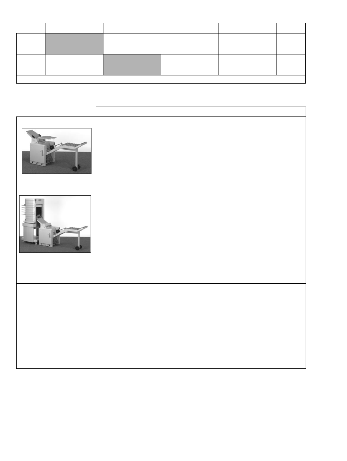
BMS (BookMaster Standard) BMP (BookMaster Pro)
Off-line • Use off-line for hand feeding
• Fitting an infeed guide is recommended
as it makes hand feeding much easier :
Motorised Infeed (MIF) or BookMaster
Infeed Guide (BIG)
• Use off-line for hand feeding
• The BookMaster Offline Control Panel
(BCP) is needed for changing sizes.
• Fitting an infeed guide is recommended
as it makes hand feeding much easier :
Motorised Infeed (MIF) or BookMaster
Infeed Guide (BIG)
BCH
Benchbase • Fit the motorised infeed to the BMS.
• Fit the Nagle Interface panel onto the
Vario or Eco-Vario.
• Deliver sets to the rear.
• This gives bi-directional communication
in error conditions.
• Benchtop height should be 710mm.
• Fit the motorised infeed to the BMP.
• Fit the Nagle Interface panel onto the
Vario or Eco-Vario.
• Deliver sets to the rear.
• This gives bi-directional communication
in error conditions.
• The BookMaster Offline Control Panel
(BCP) is needed for changing sizes.
Note : The 900-166 interface, which is sup-
plied with the Vario Oscillating Floor Base,
can be used to enable control of the BMP
from the Vario control panel (see section
7.8.2 ‘‘Connecting to the Watkiss Vario
Oscillating Floor Base.’’).
OSC Oscillating Benchbase
(configure as BCH above) • Fit the motorised infeed to the BMS.
• Fit the Nagle Interface panel onto the
Vario or Eco-Vario.
• Deliver sets to the rear.
• This gives bi-directional communication
in error conditions.
• Benchtop height should be 710mm.
• Fit the motorised infeed to the BMP.
• Fit the Nagle Interface panel onto the
Vario or Eco-Vario.
• Deliver sets to the rear.
• This gives bi-directional communication
in error conditions.
• The BookMaster Offline Control Panel
(BCP) is needed for changing sizes.
• Or, fit Interface Board 900-166 into the
OSC base, this will allow BMP settings
to be changed from the Vario control
panel (NOT Eco-Vario).
Table 1:3 BookMaster Configurations

System Description •BookMaster Overview
Watkiss BookMaster Service Manual - Issue 1 - 14/12/00 3
1.3 BookMaster Overview
The BookMaster is available as ‘Standard’ and ‘Pro’ models. The BookMas-
ter Standard has manual adjustment for sheet/book size. The BookMaster Pro
has automatic adjustment for sheet/book size.
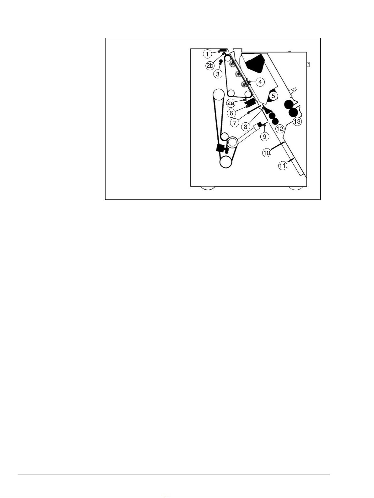
Figure 1:1 ‘‘BookMaster : Overview of key components’’ identifies the vari-
ous components involved in the BookMaster cycle. Note that items 2a, 2b and
3 are present only on the BookMaster Pro.
1.3.1 Normal Operating Cycle (when booklet-making)
Jogging: Collated sets drop into the tamper area of the BookMaster. An opti-
cal infeed sensor (1) between the sidelays detects the set entering the unit and
triggers the solenoid operated staple latch (10). The set is then initially jogged
by falling onto the staple latch. When the set is clear of the infeed sensor, the
sidelays are activated, which squares the set widthways. [BMP only: prior to
the sidelays operating, the top jog belt is activated such that the tab on the
moving top jog belt knocks any trailing sheets down (but does not actually hit
the set). An optical sensor (3) at the top of the unit (looking left to right) con-
OFB (Oscillating Benchbase with
floor conversion kit) •Use the BMS underneath the OFB.
•Fit the 905-195 VBCH Side Cover &
Remote Socket to the OFB and use the
742-394 BookMaster>OFB Interface
cable to provide uni-directional commu-
nications (BMS to Vario) in error condi-
tions.
•Vario software 7.0e or later is required.
•For Eco machines, Eco software 1.0 or
later is required.
•Use the BMP underneath the OFB.
VARIO
•Plug the BMP Interface Cable into the
900-166 External Comms Interface in
the OFB base to give full bi-directional
communications and functionality from
the Vario control panel.
ECO-VARIO
•The BookMaster Offline Control Panel is
needed for changing sizes.
•Fit the 905-195 VBCH Side Cover &
Remote Socket to the OFB and use the
742-394 BookMaster>OFB Interface
cable to provide uni-directional commu-
nications (BMS to Vario) in error condi-
tions.
•Eco software 1.0 or later is required
FLR Floor-standing base (Vario
only) •Use the BMS underneath the FLR.
•There is no bi-directional communica-
tions, therefore, although it works well,
this configuration is not recommended.
•Use the BMP underneath the FLR.
•Plug the BMP Interface Cable into the
normal FLR interface. This gives full bi-
directional communications and func-
tionality from the Vario control panel.
BMS (BookMaster Standard) BMP (BookMaster Pro)
Table 1:3 BookMaster Configurations
4Watkiss BookMaster Service Manual - Issue 1 - 14/12/00
System Description •BookMaster Overview
trols the park position (2b) and travel of the belt by detecting the tabs as they
pass.] The set is then stapled.
Note: If needed, the pre-knock (or pre-jog) function allows additional jogging
for heavy or large sheets. Selecting this option from the menu engages the edge
staple latch (7) located between the staple heads. The set will drop onto the
edge staple latch where it is pre-jogged, the staple sensor (4) will activate the
sidelays and then the set is released onto the staple latch.
Stapling: The unit is fitted with two electronically controlled Isaberg staple
heads (5), featuring 5000 capacity staple cartridges. When a staple cartridge
runs out, the corresponding red indicator light on the lid will blink once per
second. The staple legs are driven through the set and are formed against the
motorised clinchers (6). Power to the clinchers is supplied via large capacitors
on the BookMaster Interface PCB.
The staple heads and clinchers may be positioned either 115mm or 138mm
apart to suit different sheet sizes. If required, a third staple head can be fitted
to one side of the existing heads to allow corner stapling.
If stapling is not required, it can be disabled in one of two ways:
• By switching off on the control panel, in which case the staple latch
does not engage, and the sets falls straight onto the fold latch.
• By deselecting the staple head using the staple head selector button, in
which case the staple latch engages as normal. This can be useful if the
set requires additional jogging.
Folding: After stapling the sidelays are released and the staple latch is retract-
ed, allowing the set to fall on to the fold stop (11). The fold knife (9) pushes
the set through the two steel fold rollers (12), which then open up (via a planet
Figure 1:1 BookMaster : Overview of key components
1. Infeed Sensor
2a. Top Jog
2b. Top Jog Park Position
3. Top Jog Sensor
4. Staple Sensor
5. Staple Head
6. Staple Clincher
7. Edge Staple Latch
8. Edge Stitch Deflector
9. Fold Knife
10. Staple Latch
11. Fold Stop
12. Steel Fold Rollers
13. Rubber Fold Rollers
(Note : items 2a, 2b and 3 are
only on BMP)

System Description •BookMaster Overview
Watkiss BookMaster Service Manual - Issue 1 - 14/12/00 5
gear drive) and allow the set to pass on through the two rubber fold rollers (13)
and on to the outfeed or Trimmer (if fitted).
Edge Stapling: When edge stapling, the edge staple deflector fingers (8) are
moved via a lever to bypass the steel fold rollers and fold blade area. The de-
flector contacts a microswitch which engages the edge staple latch to stop the
set in the correct position. The sidelays energise as normal and the set is sta-
pled. When the edge staple latch is released the set is diverted over the steel
rollers and through the rubber rollers and on to the outfeed. The trim action of
the TrimMaster (if fitted) is automatically disabled.
[BMP only : If edge stapling and folding is required the deflector fingers are
not used. The edge staple latch is triggered by selecting EDGE+FOLD from the
SFT menu on the Vario (or BCP Offline control panel). After stapling, the set
drops to the fold stop as normal. The trim action of the TrimMaster Pro, if fit-
ted, is automatically disabled.]
Manual Cranking: The manual cranking point is used to cycle the system
when performing operations such as cleaning the fold rollers or clearing jams.
Details of how to use the manual cranking point are found in the Operating
Manualand in this Service Manual (see section 3.2.1‘‘Cycling theBookMas-
terby Hand’’ and see section 3.4.1 ‘‘Cycling the TrimMasterby Hand’’).
Mains Power: Mains power is connected via a fused socket. The status of all
the input and output functions in the unit are displayed by LEDs on the Control
PCB located under the rear cover. Power is supplied via the transformer in the
unit base to the Control PCB which in turn controls and supplies power to the
Motor Drive and Interface PCBs. The Interface PCB controls and supplies
power to the Staple Heads and Clinchers.
Firmware and Software:
Firmware and software in the BMP is distinct from that used in the BMS - they
are not compatible.
BMP : Firmware is in the form of an EPROM on the Control PCB which
stores the basic information needed to communicate with a PC. An RS232
connector on the Control PCB is used for loading software into the BMP from
aPC (see4.3.1 ‘‘Loading Software’’).
BMS :Firmwareisin the formofan EPROMon the Interface PCB. Soft-
ware changes can only be made by changing the EPROM itself.
Zerox: The Zero Crossing board (Zerox) is connected to the Eco-Vario Inter-
face PCB (900-141) and is removable. The Zerox generates a pulse, synchro-
nised with the mains AC input, 100 times a second (50hz) or 120 times a
second (60hz) which is used primarily as a timing signal for the BookMaster.
The Zerox will also react to mains power fluctuation by turning the motor off.
1.3.2 Status Indication
Indicator lights and audible bleeps indicate the status of the BookMaster and
the staple heads.

6Watkiss BookMaster Service Manual - Issue 1 - 14/12/00
System Description •BookMaster Overview
Status Indicator Light: The yellow indicator light on the BMS/BMP shows
the status of the unit.
Staple Head Indicator Lights: The red indicator lights on the BMS/BMP lid
show the status of the corresponding staple head.
Startup and Error Bleeps: A series of audible ‘bleeps’ indicate the overall
status of the BookMaster.
• = short bleep
— = long bleep
~ = pause
INDICATOR LIGHT MODE BMS/BMP STATUS
Blinking once per second The unit is ready to run
Constantly illuminated The unit is running
Blinking rapidly There is a jam or other error
Not illuminated BMP/TMP lid is open, paper is stuck in the paper
path or the unit is not switched on
Table 1:4 Status Indicator Lights
INDICATOR LIGHT MODE STAPLE HEAD STATUS
Blinking once per second The staple cartridge is about to or has run out
Constantly illuminated The staple head is selected and ready to run
Blinking rapidly There is a staple head jam or other error
Not illuminated The Staple head is not selected
Table 1:5 Staple Head Indicator Lights
BLEEPS DESCRIPTION CAUSE
•~ ••Normal startup bleeps
•••••••Continuous rapid bleeps 28v rail error / F2 fuse blown
—————Continuous long bleeps 900-100 Zerox PCB is missing
or faulty
•••Three rapid bleeps at power-up Software corruption
————— 3 second bleep when a load is
applied to a faulty device Short cirucit on 28v ouput - ie.
a solenoid
•~ •~ •~ •Short bleep every 5 seconds
before the normal startup bleeps Address error Staple Heads/
PIC system. If self recovery is
not achieved, use Terminal
Emulator PICI command for
fault diagnostics.
•Single short bleep when infeed
sensor is covered Internal comms error, or
uncleared jam condition. This
bleep is also emitted when
Top Jog is disabled
Table 1-6 : Error bleeps
System Description •TrimMaster Overview
Watkiss BookMaster Service Manual - Issue 1 - 14/12/00 7
1.4 TrimMaster Overview
The TrimMaster is a separate unit which is designed to integrate with the
BookMaster. Power and communications for the TrimMaster are taken from
two sockets on the BookMaster into an interface PCB. All the components of
the TrimMaster are controlled from this board. The TrimMaster is secured to
the BookMaster by docking hooks.
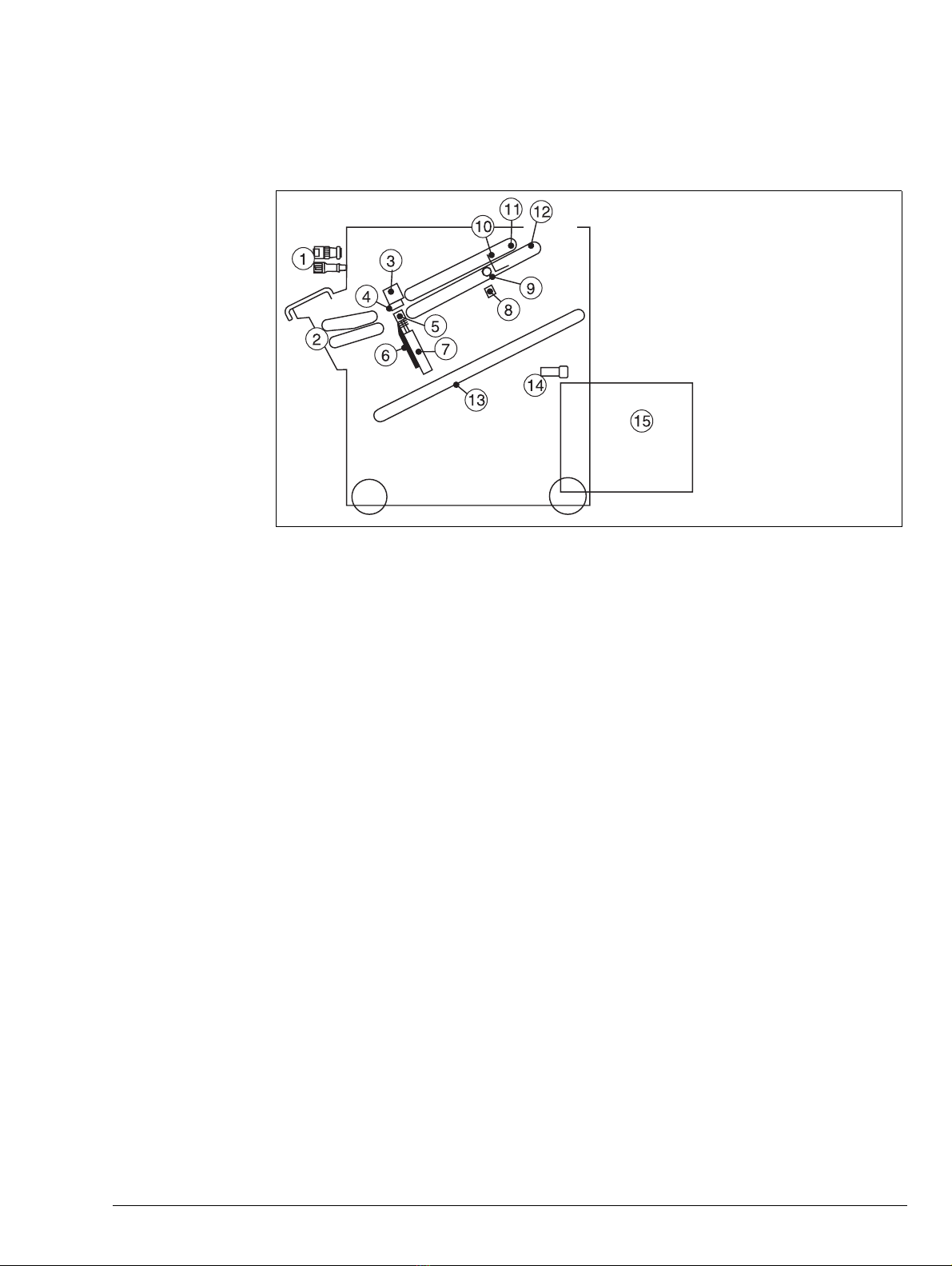
Figure 1:2 TrimMaster : Overview of key components
Note that the TrimMaster is only compatible with the BookMaster. The Trim-
Master Pro is only compatible with the BookMaster Pro.
TrimMaster Blade: The TrimMaster has a single blade (6) which is driven up
past an anvil (4) in a scissor action. The book enters the TrimMaster into the
infeed conveyor (2) and then between the blade and anvil. A solenoid, trig-
gered by a signal from the staple sensor in the BookMaster, pushes the paper
stop latch (10) into its vertical position. The latch stops the book in the re-
quired position. The book is then held at the folded edge by a spring tensioned
roller clamp shaft (9) and at the trailing edge by a steel clamp (5) before being
trimmed. A sensor (8) in the conveyor detects the successful passage of the
book and triggers the outfeed conveyor.
TrimMaster Blade Drive: Drive to the TrimMaster blade is provided by a
motor/gearbox in the base. Power is transferred from the drive motor via a
toothed belt to the clutch and from there to a connection arm assembly. A
crank on the bottom end of each arm converts the rotational drive of the motor
into the lateral movement needed by the blade. The gearbox oil should not re-
quire refilling.
Conveyor: The motor also drives the TrimMaster conveyor via a chain drive
and clutch. An adjustable tensioner is fitted in the chain drive. The TrimMas-
ter may be manually cycled when performing operations such as blade re-
placement (see section 3.4.1 ‘‘Cycling the TrimMaster by Hand’’).
Conveyor Clamp: The TrimMaster conveyor clamp rollers hold the spine of
the booklet during trimming. They are pre-set in the factory but are adjustable
if required (see section 3.4.2 ‘‘Conveyor Clamp Adjustment’’).
1. Connections to BookMaster
2. Infeed Conveyor
3. Anvil Clamp Bar
4. Anvil
5. Steel Clamp
6. Blade
7. Bolster
8. Sensor
9. Conveyor Clamp Roller
10.Paper Stop Latch
11.Upper Conveyor
12.Lower Conveyor
13.Waste Conveyor
14.Trim Bin Full Sensor
(TMP only)
15.Trim Bin

8Watkiss BookMaster Service Manual - Issue 1 - 14/12/00
System Description •BookMaster Outfeed Conveyor (BOC)
Trim Bin: Off-cuts from the blade drop onto the waste conveyor and are de-
livered into the external trim bin. The TrimMaster Pro is fitted with an optical
sensor which stops the unit when the bin is full.
1.5 BookMaster Outfeed Conveyor (BOC)
The BookMaster Outfeed Conveyor takes finished documents from the out-
feed of the BookMaster or the TrimMaster and conveys them to an integral
payout table. Power may be taken from the TrimMaster or the BookMaster.
Figure 1:3 BookMaster Outfeed Conveyor
1.6 BookMaster Motorised Infeed (BMI)
The Motorised Infeed (BMI) is an optional module which accepts sheets and
automatically feeds them into the BookMaster. This may be used :
• as an aid to hand feeding
• to accept sets from a Vario benchtop collator feeding to the rear
• to accept sets from another manufacturer’s collator or other machine
• as a collecting station online to a Watkiss Vario, so that sets/sheets can
be collected in the BMI, and are released on a signal from the Vario
(see section 7.5.1 ‘‘Using the BMI as a collecting station’’)
Figure 1:4 BookMaster Motorised Infeed
Motorised Infeed
P/N 041-571
Paper Tray
Sidelay
System Description •BookMaster Infeed Guide (BIG)
Watkiss BookMaster Service Manual - Issue 1 - 14/12/00 9
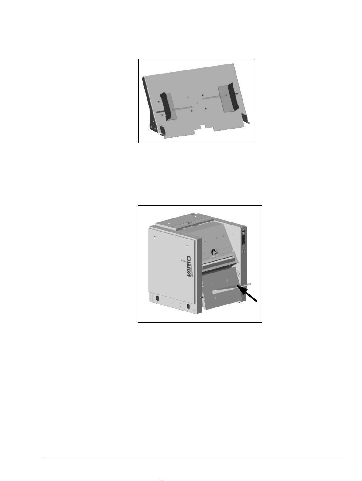
1.7 BookMaster Infeed Guide (BIG)
The BookMaster Infeed Guide is designed to aid hand feeding sets into the
BookMaster. It is a low cost alternative to the Motorised Infeed. It can NOT
be used as an infeed when connecting the BookMaster to collators.
Figure 1:5 BookMaster Infeed Guide
1.8 BookMaster Receiving Tray (BRT)
The BookMaster Receiving Tray (BRT) is designed as a low cost alternative
to the BookMaster Outfeed Conveyor (BOC). For ease of use, we recommend
customers purchase the BOC in preference to the BRT.
Figure 1:6 BookMaster Receiving Tray

10 Watkiss BookMaster Service Manual - Issue 1 - 14/12/00
System Description •BookMaster Offline Control Panel (BCP)
1.9 BookMaster Offline Control Panel (BCP)
The BookMaster Offline Control Panel (BCP) provides control of the Book-
Master Pro and TrimMaster Pro when they are used off-line (see Table 1:3,
BookMaster Configurations).
Figure 1:7 BookMaster Offline Control Panel
1.10 Fuses
Fuses on the PCBs protect the motors and the voltage rails in the system.
The table below lists the fuses fitted in the BookMaster Standard.
Warning When changing a fuse, always ensure that the power is switched off and the
mains disconnected. Also ensure that the fuse holder grips the fuse firmly. A
loose fuse holder may cause connection problems. If needed, bend the tabs on
the holder to tighten the fit.
1.10.1 BookMaster Standard
Transformer Taps: The transformer is fitted with adjustable taps (blue)
which must be set to the correct position for the input voltage. Setting posi-
tions are shown on the transformer PCB. Details of the tap settings are shown
in the tables below.
LOCATION FUSE FUNCTION RATING
Power input
socket - Main line fuse x2
(1 per line) 240V - 5.0A, HRC Quick acting, F
115V - 10A, HRC Quick acting, F
Motor Drive PCB F1 9V Rail 3.15A Glass, Anti-surge, T
F2 28V Rail 6.3A Glass, Anti-surge, T
F3 Drive motor 230V 2.0A Glass, Anti-surge, T
115V 3.15A Glass, Anti-surge, T
Transformer F6 Transformer 3.15A HRC Anti - surge, T
Table 1-7 : BookMaster Standard Fuses
TAP SETTING INPUT
100 93 - 110V
115 105 - 127V
200 187 - 220V
230 210 - 254V
Table 1-8 : Transformer Tap Settings

System Description •Fuses
Watkiss BookMaster Service Manual - Issue 1 - 14/12/00 11
1.10.2 BookMaster Pro
Transformer Taps: The transformer is fitted with adjustable taps (blue)
which must be set to the correct position for the input voltage. Setting posi-
tions are shown on the transformer PCB. Details of the tap settings are shown
in the tables below.
LOCATION FUSE FUNCTION RATING
Power input
socket - Main line fuse x2
(1 per line) 240V - 5.0A, HRC Quick acting, F
115V - 10A, HRC Quick acting, F
Motor Drive PCB F1 9V Rail 3.15A Glass, Anti-surge, T
F2 24V Rail 6.3A Glass, Anti-surge, T
F3 Drive motor 230V 2.0A Glass, Anti-surge, T
115V 3.15A Glass, Anti-surge, T
Transformer F6 Transformer 3.15A HRC Anti - surge, T
Table 1-9 : BookMaster Pro Fuses
TAP SETTING INPUT
100 93 - 110V
115 105 - 127V
200 187 - 220V
230 210 - 254V
Table 1-10 : Transformer Tap Settings

12 Watkiss BookMaster Service Manual - Issue 1 - 14/12/00
System Description •Fuses

Tools and Materials •Recommended Tools
Watkiss BookMaster Service Manual - Issue 1 - 04/12/00 13
Chapter 2 Tools and Materials
It is recommended that Watkiss engineers carry the following tools and mate-
rials with them. Watkiss part numbers are included where relevant, although
many of the recommendations are standard tools which are readily available.
USA readers : Please note that the terms ‘spanner’ and ‘wrench’ are inter-
changeable.
2.1 Recommended Tools
PART NO. DESCRIPTION
952-032 Screwdriver - POZI, No 1
952-020 Screwdriver - FLAT, 6.5mm
952-026 Screwdriver - Electrical + neon
952-059 Spanner - Combination, 5mm
952-060 Spanner - Combination, 5.5mm
952-062 Spanner - Combination, 7mm (M4)
952-063 Spanner - Combination, 8mm (M5)
952-066 Spanner - Combination, 10mm (M6)
952-067 Spanner - Combination, 13mm (M8)
955-005 Spanner - 19mm A/F
Spanner - 10mm A/F
952-002 Special Tool - Spanner - Single End, 17mm (M10)
952-053 Pliers - long nose, small
952-056 Pliers - Side cutters, small
952-076 Circlip Pliers (external)
952-043 Allen Key ‘L’- 2.0mm
952-044 Allen Key ‘L’- 2.5mm
952-045 Allen Key ‘L’- 3.0mm
952-046 Allen Key ‘L’- 4.0mm
952-047 Allen Key ‘L’- 5.0mm
952-048 Allen Key ‘L’- 6.0mm
952-049 Allen Key ‘L’- 8.0mm
952-091 Allen Key - 3.0mm, Blue Handled
952-096 Ball Ended Handled Allen Key - 3.0mm
952-004 6”Rule (steel)
952-013 12”Rule
3,4,5mm Pin Punches
3/4LB Ball Pein Hammer
952-183 ‘E’Clip Applicator 7B - Straight
BookMaster Setting Plate - Watkiss Tool 10106
Table 2:1 Recommended Tools

14 Watkiss BookMaster Service Manual - Issue 1 - 04/12/00
Tools and Materials •Consumables
2.2 Consumables
PART NO. DESCRIPTION
Lint Free Cloth
951-007 Loctite 242 (Thread Locking Compound)
951-152 Anti-seize Compound Lubricant
Table 2:2 Consumables
This manual suits for next models
2
Table of contents
Other Watkiss Automation Booklet Maker manuals


