Watkiss Automation Automatic SpineMaster User manual

Watkiss Automatic SpineMaster Service Manual - Edited 17/06/04
Watkiss
AutomaticSpineMaster
Service Manual
Issue Date : 17 June 2004
Issue Number : 1a
Part Number : 969-235
Watkiss Automation Ltd
1 Blaydon Road,
Middlefield Industrial Estate,
Sandy, Beds SG19 1RZ
United Kingdom
tel: +44 (0)1767 682177
fax: +44 (0)1767 691769
email: [email protected]

Watkiss Automatic SpineMaster Service Manual - Edited 17/06/04
Conventions
The following conventions are used in this manual:
WARNING Warning messages alert you to a specific procedure or practice which, if
not followed correctly, could cause serious personal injury.
CAUTION Caution messages appear before procedures which, if not observed, could re-
sult in damage to equipment.
© Watkiss Automation Limited 2004
All Rights Reserved.
Reproduction, adaptation, or translation without prior written permission is prohibited, except as allowed
under the copyright laws.
Warranty
The information contained in this document is subject to change without notice.
Watkiss Automation Limited makes no warranty of any kind with regard to this material, including, but not
limited to, the implied warranties of merchantability and fitness for a particular purpose.
Watkiss Automation Limited shall not be liable for errors contained herein or for incidental or consequential
damage in connection with the furnishing, performance or use of this material.


Watkiss Automatic SpineMaster Service Manual - Edited 17/06/04

Introduction •
Watkiss Automatic SpineMaster Service Manual - Edited 17/06/04 1 - 1
Chapter 1 Introduction
SECTION PAGE
Introduction . . . . . . . . . . . . . . . . . . . . . . . . . . . . . . . . . . . . . . . . . . . . . . 2
Product Variants . . . . . . . . . . . . . . . . . . . . . . . . . . . . . . . . . . . . . . . . 2
Terminology . . . . . . . . . . . . . . . . . . . . . . . . . . . . . . . . . . . . . . . . . . . 2
Safety . . . . . . . . . . . . . . . . . . . . . . . . . . . . . . . . . . . . . . . . . . . . . . . . . . . 3
Warnings . . . . . . . . . . . . . . . . . . . . . . . . . . . . . . . . . . . . . . . . . . . . . . . . 3
Warning Labels . . . . . . . . . . . . . . . . . . . . . . . . . . . . . . . . . . . . . . . . . . . . 3
Orientation . . . . . . . . . . . . . . . . . . . . . . . . . . . . . . . . . . . . . . . . . . . . . . . 4
Product Overview . . . . . . . . . . . . . . . . . . . . . . . . . . . . . . . . . . . . . . . . . . 4
Paper Path . . . . . . . . . . . . . . . . . . . . . . . . . . . . . . . . . . . . . . . . . . . . 4
Basic Operating Principles . . . . . . . . . . . . . . . . . . . . . . . . . . . . . . . . 5
Book Thickness Adjustment . . . . . . . . . . . . . . . . . . . . . . . . . . . . . . . 7
Operating Modes . . . . . . . . . . . . . . . . . . . . . . . . . . . . . . . . . . . . . . . 7
Error Indicator / Reset Button . . . . . . . . . . . . . . . . . . . . . . . . . . . . . . 8
Routine Maintenance . . . . . . . . . . . . . . . . . . . . . . . . . . . . . . . . . . . . . . . 8

1 - 2 Watkiss Automatic SpineMaster Service Manual - Edited 17/06/04
Introduction • Introduction
1.1 Introduction
The Watkiss SpineMaster post-processes stitched or stapled booklets to give
them the professional flat appearance of a perfect bound book, but with the se-
curity of a stitched spine. The resulting SquareBack books are flat, making
them easy to stack, handle and pack.
1.1.1 Product Variants
The Automatic SpineMaster is available as a standard machine, suitable for
use online to Watkiss booklet-makers or off-line.
Product variants are also available for Duplo, Bourg and Nagel booklet-mak-
ers. The function of the unit is unchanged. Only the infeed assembly and base
assembly are different.
1.1.2 Terminology
In this manual the Watkiss Automatic SpineMaster is referred to by its product
code ‘ASM’.
Where instructions refer to particular product variants, they are referred to by
the product code, suffixed with ‘B’ (Bourg), ‘D’ (Duplo) or ‘N’ (Nagel).
i.e. ASMB, ASMD, ASMN.
Introduction • Safety
Watkiss Automatic SpineMaster Service Manual - Edited 17/06/04 1 - 3
1.2 Safety
Please observe good Health and Safety practices when lifting or moving ma-
chinery. When it is necessary to have power connected to the machine whilst
covers are removed, always ensure that extreme caution is taken to avoid per-
sonal injury.
Note: The disconnect device is the appliance inlet.
1.3 Warnings
The following warnings are used in this manual:
Warning Warning messages alert you to a specific procedure or practice which, if not
followed correctly, could cause serious personal injury.
Caution Caution messages appear before procedures which, if not observed, could re-
sult in damage to equipment.
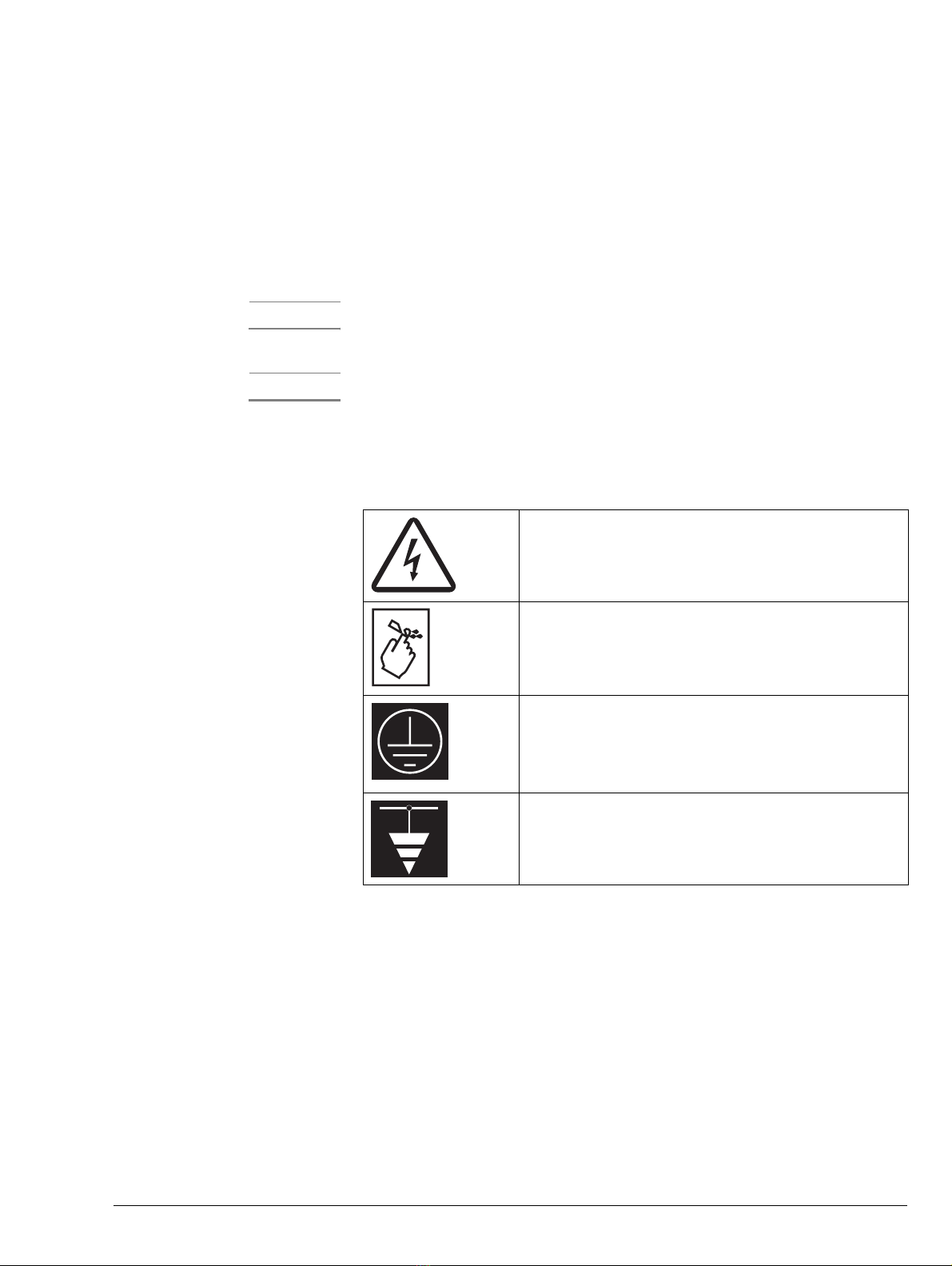
1.4 Warning Labels
The following warning labels are used in the Watkiss Automatic SpineMaster.
Indicates high voltages are present.
Label is sometimes accompanied with voltage indication.
Black figure on Yellow background.
Indicates danger of crush or cut injuries if fingers or other
body parts are inserted into this part of the machine.
Black figure on Yellow background
Indicates the Safety Earth
White figure on green background
Indicates a Functional Earth
White figure on green background
Table 1:1 Warning Labels

1 - 4 Watkiss Automatic SpineMaster Service Manual - Edited 17/06/04
Introduction • Orientation
1.5 Orientation
Where procedures or descriptions refer to the RH (right hand) or LH (left
hand) side of the machine, this is always as viewed from the delivery (outfeed)
end of the machine.
1.6 Product Overview
1.6.1 Paper Path
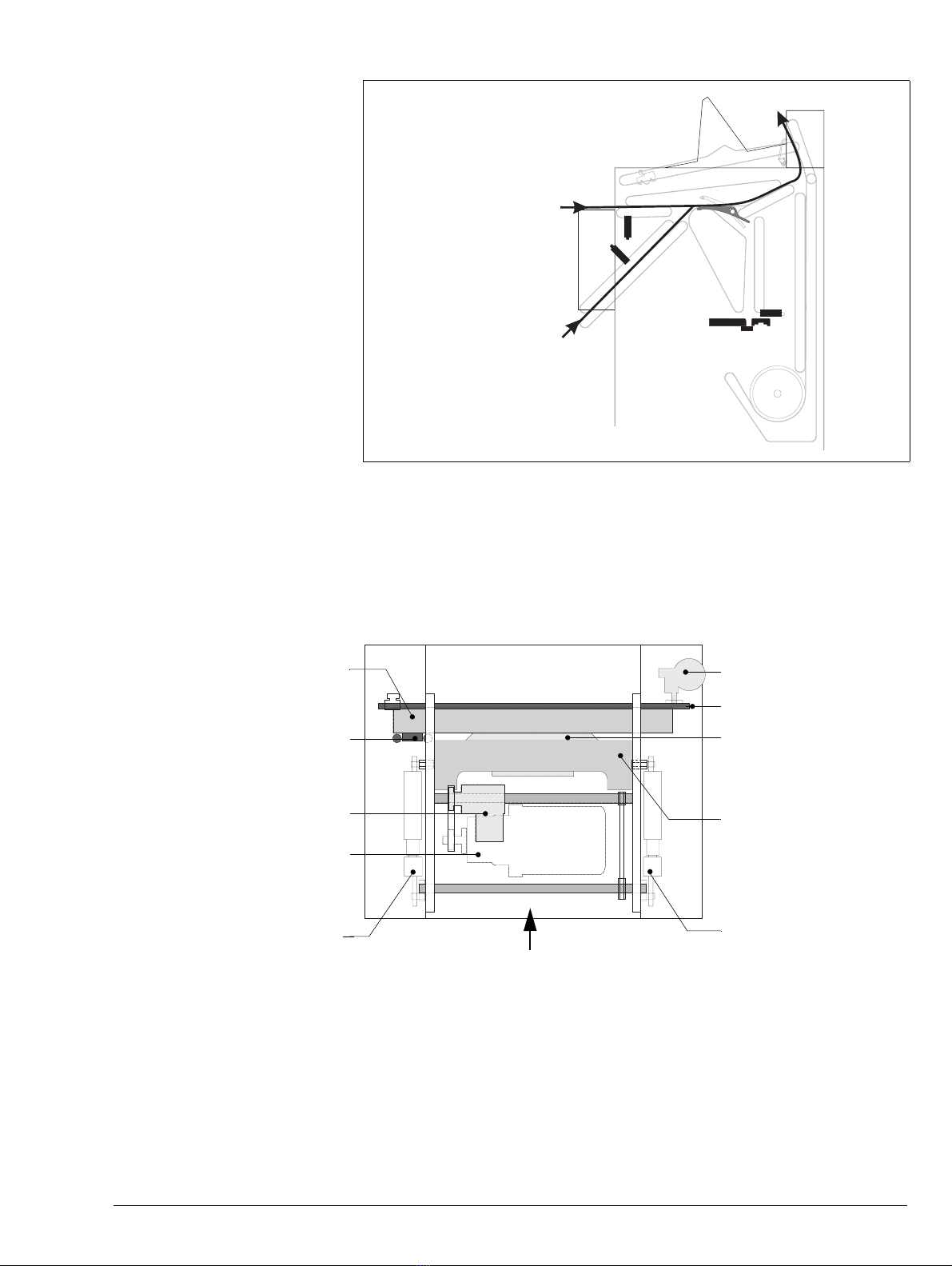
Figure 1:2 Paper Path - SquareBack Mode
Figure 1:1 Top view (ASM version shown)
Infeed
RH sideLH side
Delivery (outfeed) end
Upper Infeed
Lower Infeed
Introduction • Product Overview
Watkiss Automatic SpineMaster Service Manual - Edited 17/06/04 1 - 5
Figure 1:3 Paper Path - Bypass Mode
1.6.2 Basic Operating Principles
Booklets are inserted at either the Upper Infeed or the Lower Infeed. The In-
feed Sensors activate the Drive Motor and the booklets are transported from
the infeed, to the top of the machine and into the Booklet Loading Slot, where
they drop squarely onto the Stop (see Figure 1:5)
Upper Infeed
Lower Infeed
Figure 1:4 Automatic SpineMaster Component Diagram (top View)
Anvil
Carriage
Clutch
Drive Motor
RH Cam Link
Carriage Motor
Stop
Bolster
LH Cam Link
Transverse Chain
Infeed

1 - 6 Watkiss Automatic SpineMaster Service Manual - Edited 17/06/04
Introduction • Product Overview
The Clamp Optical Sensor detects the presence of the booklet, and activates
the Carriage Motor.
After a preset pause, the Clutch on the Drive Motor is activated, which allows
the Drive Shaft to make one complete revolution. This drives the Bolster to-
wards the Anvil (the rotary motion of the Motor is converted to this lateral
movement via two Cam Links on the chain-driven Drive Shaft). The Bolster
and Anvil clamp the booklet in place, just above the spine (see Figure 1:6).
Collectively the Bolster and Anvil are known as the ‘Clamp’.
The spine is formed by the Roller Follower which is transported on the Car-
riage (see Figure 1:6). This Carriage is driven by the Transverse Chain, pow-
ered by the 24V Motor. With the booklet firmly clamped, the Carriage travels
the length of the spine, and the Roller Follower presses the spine into the re-
quired square profile. For this to happen, the Stop must first be moved out of
the way, so the Carriage is fitted with vertical Cam Rollers that push the Stop
rearwards.
When the Carriage reaches the end of the Carriage Guide, it activates either
the LH or RH Limit Sensor. There is one of these sensors at either end of the
Guide, because the Carriage can travel in both directions. For more informa-
tion on this see Section 1.6.4.
WARNING If for any reason the Carriage is stopped before it reaches one of the Limit
Sensors, it will move towards either the RH or LH Limit Sensor once power is
Bolster
Anvil
Stop
Booklet
Figure 1:5 Booklet is dropped onto the Stop
Figure 1:6 Clamp Closes.
Figure 1:7 Carriage Triggered.

Introduction • Product Overview
Watkiss Automatic SpineMaster Service Manual - Edited 17/06/04 1 - 7
restored Therefore, always disconnect the ASM from the mains power supply
before putting hands or tools inside the machine..
Once the Carriage reaches either sensor, the Carriage stops and the Clutch is
engaged so that the Drive Motor releases the Clamp. The Drive Motor will
continue to run for about 15 seconds after the last book has been removed.
1.6.3 Book Thickness Adjustment
This control alters the height of the Stop. The control is turned by hand, which
operates a worm drive via a toothed belt. If the control is set to a thicker book-
let size, the Stop will be lowered, leaving more of the spine exposed to the Car-
riage. This is necessary to form the wider spine a thicker booklet requires.
1.6.4 Operating Modes
Single Pass: The ASM will process the booklet a single time. This is the de-
fault setting, and is suitable for the vast majority of booklets. Each subsequent
booklet is formed by the Carriage travelling in the opposite direction, i.e if the
first booklet is formed by the Carriage travelling from left to right, the second
booklet will be formed by the Carriage travelling from right to left.
Double Pass: The ASM will process the booklet twice. This can be useful for
thick, inflexible covers which are more resistant to re-forming. In this mode,
the Carriage passes along the booklet’s spine twice (once in either direction)
SquareBack Mode: The booklets will be processed and receive a squared
spine (SquareBack).
Figure 1:8 Clamp Opens.
Figure 1:9 Book Thickness Adjustment
Max.
Min.

1 - 8 Watkiss Automatic SpineMaster Service Manual - Edited 17/06/04
Introduction • Routine Maintenance
Bypass Mode: The booklets will bypass the SquareBacking process and will
be delivered straight to the stacker. The Book Diverter, activated by a sole-
noid, diverts the booklets directly to the stacker.
1.6.5 Error Indicator / Reset Button
This indicator/button performs several functions -
• A green light indicates an error. Correct the error and then press the
button to reset the ASM.
• The button can be used to start the machine if it is not automatically
started by hand-feeding or by connected equipment.
• When hand-feeding, the green light flashes as each booklet is proc-
essed. Another booklet can be inserted when the light goes out.
1.7 Routine Maintenance
Effective rountine maintenance helps prevent machine breakdowns and en-
sures that the SpineMaster delivers optimum performance.
Routine maintenance should only be conducted by technicians who have re-
ceived product-specific training.
The routine maintenance schedule sheet in this section may be photocopied for
this purpose and we recommend that a copy is kept for your records.
The normal service interval for the ASM is 12 months. This interval should be
reduced if the ASM is subject to heavy use.
Double Pass
Single Pass
SquareBack Mode
Bypass Mode
Error Indicator / Reset Button
Figure 1:10 Operating Modes

Introduction • Routine Maintenance
Watkiss Automatic SpineMaster Service Manual - Edited 17/06/04 1 - 9
ASM Routine Maintenance Schedule
ASM Serial Number : F/W Version :
CHECK LIST CHECKED COMMENTS / NOTES
1. Check all fixing screws are tightened
2. Check drive chains and transverse chain for ten-
sion and wear
3. Lubricate drive chains using chain lubricant. DO
NOT lubricate the transverse chain.
4. Check/clean belts. Use cloth dampened with
soapy water or alcohol (iso-propanol). DO NOT
use blanket wash.
5. Check that the bolster is firmly held by all six cam
bearings
6. Clean out any paper debris
7. Clean the carriage roller and stop (see 4.3)
8. Check the stop is damped correctly and adjust if
necessary (see 4.7.8)
9. Check that the carriage runs square and tight to
the anvil and bolster
10. Check that the bolster is not burred by badly sta-
pled booklets. Deburr if required (see 4.7.9).
11. Check that the carriage parks beyond the booklet
feed slot, but does not hit either end stop. Adjust
the tension in the transverse chain and then reset
the limit sensors if necessary (see 4.7.2)
12. Check holding magnet is secure and correctly set.
(see 4.8.1)
13. Check condition of outfeed leaf springs (257-
511). Replace if necessary.
14. Check the condition of all electrical cables.
Ensure all connectors are seated correctly
15. Check condition of the interface cable between
ASM and trimmer.
Checks completed by : Date :
Table 1:2 ASM Routine Maintenance Schedule

1 - 10 Watkiss Automatic SpineMaster Service Manual - Edited 17/06/04
Introduction • Routine Maintenance

Status Indicator RAPs •
Watkiss Automatic SpineMaster Service Manual - Edited 17/06/04 2 - 1
Chapter 2 Status Indicator RAPs
Entry RAP . . . . . . . . . . . . . . . . . . . . . . . . . . . . . . . . . . . . . . . . . . . . . . . . 2
AC Mains RAP . . . . . . . . . . . . . . . . . . . . . . . . . . . . . . . . . . . . . . . . . . . . 3
Error Indicator RAP . . . . . . . . . . . . . . . . . . . . . . . . . . . . . . . . . . . . . . . . 4
Jammed Booklet RAP . . . . . . . . . . . . . . . . . . . . . . . . . . . . . . . . . . . . . . . 5
Carriage Motor and Transverse Chain RAP . . . . . . . . . . . . . . . . . . . . . . . 6
2 - 2 Watkiss Automatic SpineMaster Service Manual - Edited 17/06/04
Status Indicator RAPs • Entry RAP
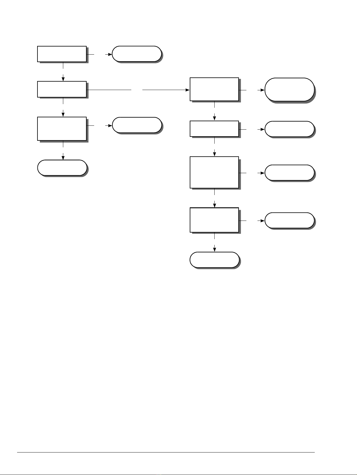
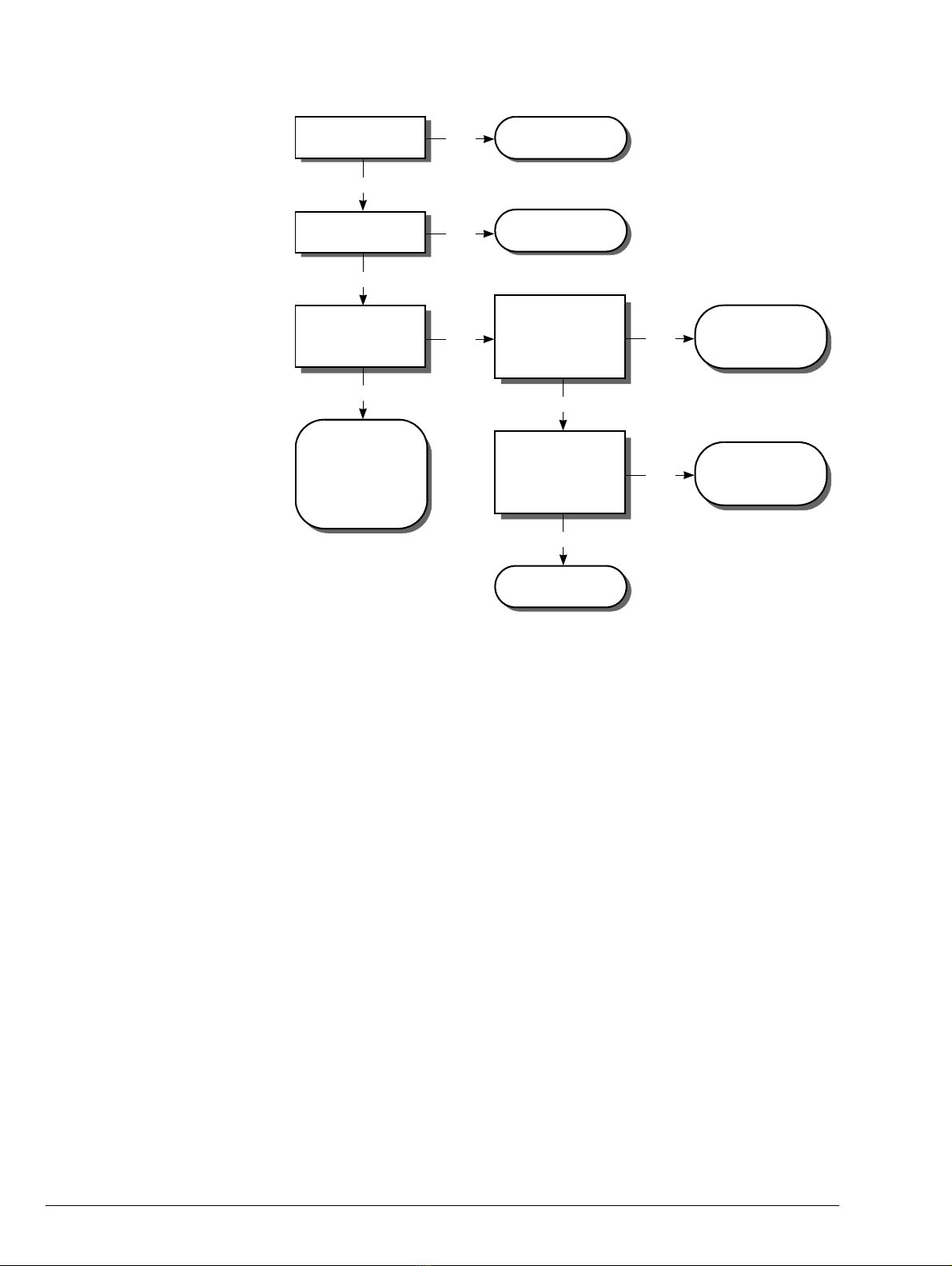
2.1 Entry RAP
Go to Error Indicator
RAP (see 2.3).
Check the
Transformer Fuse
(see 7.1).
Check the F3 fuse
on PCB 900-141.
Does the Main Motor
rotate when a start
signal is present?
Check Wiring/
Motor.
Check Drive
Chains (see 4.8.7).
Is the Main Power
Switch illuminated?
Go to AC Mains
RAP (see 2.2).
Is the Error Indicator
Light illuminated?
Is the Stacker Sup-
port triggering the
Stacker Full Sensor?
Reset Stacker
Support.
Is LED1 on the Trans-
former Input PCB illu-
minated?
Does LED1 on PCB
900-141 illuminate
when a start signal
is present?
Is LED13 on PCB
900-197 flashing?
Yes
No
Yes
No
Yes
No
Yes
Replace PCB
900-197.
No
Yes
Yes
Yes
No
No
No
Status Indicator RAPs • AC Mains RAP
Watkiss Automatic SpineMaster Service Manual - Edited 17/06/04 2 - 3
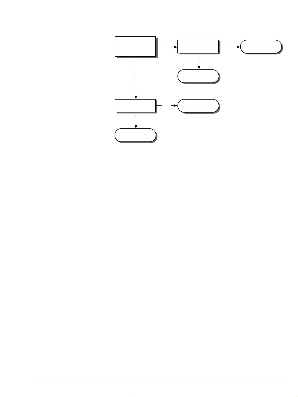
2.2 AC Mains RAP
The mains switch is not illuminated.
Is there mains
power to the Mains
Lead end?
Check mains
supply.
Is the fuse* in the
Input Socket OK? Replace fuse*.
Replace complete
Input Socket.
No
Yes
Is the fuse* in the
plug OK?
Yes
No Replace the fuse*.
No
Yes
*Fuses (see 7.1).
2 - 4 Watkiss Automatic SpineMaster Service Manual - Edited 17/06/04
Status Indicator RAPs • Error Indicator RAP
2.3 Error Indicator RAP
The machine will not run and the Error Indicator Light is illuminated.
Is there a booklet
jammed inside the
ASM?
Is LED9* (Guard)
illuminated?
Check/Replace
PCB 900-197.
Close the Guards.
Are the Guards
properly closed? No
Check the Guard
Switch and wiring.
Remove the
jammed booklet. If
the problem per-
sists go to the
Jammed Booklet
RAP (see 2.4)..
Does LED10/11*†
illuminate when a
booklet is pushed
into the Infeed?
Check/replace
Infeed Sensor (see
4.8.19)./(see
4.8.20).
Does LED15* illu-
minate when a
booklet is on the
Clamp Stop?
Check/replace
Clamp Optical
Sensor (see 4.7.4).
Yes
No
Yes
No
Yes Ye s
No
Yes
No
*on PCB 900-197
† LED10 for ASM & ASMN
LED11 for ASMB & ASMD
Status Indicator RAPs • Jammed Booklet RAP
Watkiss Automatic SpineMaster Service Manual - Edited 17/06/04 2 - 5
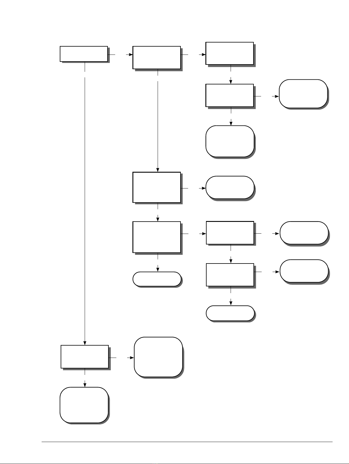
2.4 Jammed Booklet RAP
Is the booklet
jammed in the
Clamp?
Clean the conveyor
belts, ensure the
booklet feeds in
square and that it
is folded as tightly
as possible.
Is the booklet jammed
before the Clamp?
Is the booklet thin,
with only a few
sheets?
Clean the conveyor
belts, ensure the
booklet feeds in
square and it is not
folded too tightly.
Refer to Clearing a
Paper Jam proce-
dure (see 4.4).
Switch the power off
then on. Does the
Clamp open and
release the booklet?
Remove jammed
booklet and con-
tinue operation.
Is all OK?
No fault found.
Clear jam again. Has
the jammed booklet
spine been formed?
Check Carriage
Motor and Transverse
Chain (see 2.5).
Is the booklet thin,
with only a few
pages?
Check Paper Stop
Holding Magnet
(see 4.8.1).
Is the booklet
jammed in the
Upfeed Conveyor?
Is the booklet thin,
with only a few
pages?
Clean the Conveyor
Belts and check that
the spine is not
being over crushed.
No
Yes
Check Conveyor
Belts are correctly
positioned and not
worn.
No
No
Yes
Yes
Ye s
Ye s
Yes
Yes
Yes
Yes
No
No
No
No
No
Go to Thin Books
RAP (see 3.2).

2 - 6 Watkiss Automatic SpineMaster Service Manual - Edited 17/06/04
Status Indicator RAPs • Carriage Motor and Transverse Chain RAP
2.5 Carriage Motor and Transverse Chain RAP
Tension Chain (see
4.7.1).
Check/replace
Clamp Optical Sen-
sor (see 4.8.21).
Replace PCB
900-197.
Replace Drive
Motor (see 4.8.16).
Is the Transverse
Chain in place?
Does the Carriage
Motor run?
Is the Chain correctly
tensioned (see
4.7.1).
Does LED15 on
PCB 900-197 illumi-
nate when booklet is
on Stop?
Is the resistance
across the Motor
Balast Resistor
correct (68 Ohms
+/-5%)?
Yes
Yes
No
No
Yes
Replace Resis-
tor (see 4.8.4).
No
Yes
No
Re-fit Chain to
Sprockets and ten-
sion (see 4.7.1).
Is the Chain Broken?
Replace/repair
Chain (see 4.8.6).
Yes
No
Yes
Is there drive from
the Motor to the
Carriage?
Is the Roller
Assembly jammed?
Yes
Free Roller Assem-
bly (see 4.5).
Yes
No
Tighten Trantorque
Bush on Drive
Sprocket (see Fig-
ure 4:36).
Is the Drive Motor
faulty?
No
No
Yes
Table of contents
Other Watkiss Automation Booklet Maker manuals


