WDT Duftdos UNPL User manual

Operation manual 20997-Duftdos-UNPL (09/16) Page 1 von 9
Duftdos –UNPL –with contact sensor
Table of contents Page
1. Instruction fort the manual............................................................................................................................................................. 2
1.1 Validity ...............................................................................................................................................................................2
1.2 Target group .......................................................................................................................................................................2
1.3 Storage of the manual .........................................................................................................................................................2
1.4 Further informations ............................................................................................................................................................ 2
1.5 Used symbols.......................................................................................................................................................................2
2. Saftey............................................................................................................................................................................................3
2.1 Technical safety advice.........................................................................................................................................................3
2.2 Use in accordance with regulations....................................................................................................................................... 4
3. Delivery.........................................................................................................................................................................................4
4. Function ........................................................................................................................................................................................4
5. Technical Data...............................................................................................................................................................................5
6. Fragrance pump.............................................................................................................................................................................5
6.1 Change the hose set ............................................................................................................................................................. 6
6.2 Sparepartlist persitaltic pump frangrance.............................................................................................................................. 6
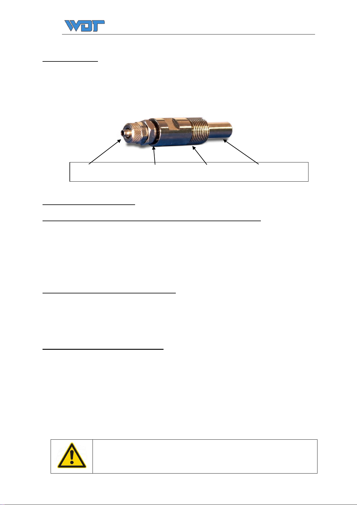
6.3 Dosing valve.......................................................................................................................................................................7
6.4 Spare part list dosing valve...................................................................................................................................................7
7. Console for frangrance canister (optional).......................................................................................................................................7
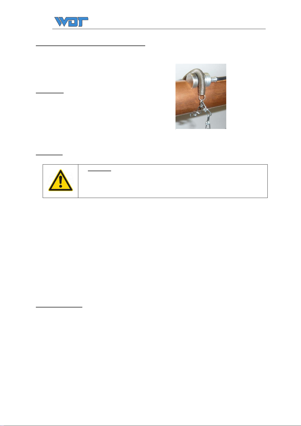
8. Installation / Commissioning / Dosing............................................................................................................................................. 7
9. Maintenance..................................................................................................................................................................................8
10. Wiring diagramme.........................................................................................................................................................................9
11. Change the set switching temperature............................................................................................................................................. 9

Operation manual 20997-Duftdos-UNPL (09/16) Page 2 von 9
1. Instruction fort the manual
1.1 Validity
This manual describes the installation, commissioning / taking into operation and operation of the unit.
1.2 Target group
Only the trained persons in the functions of the device are allowed to operate. Connection works must be carried out by suitably trained
professionals.
1.3 Storage of the manual
All manuals for the device and the installed components must be stored in the immediate vicinity of the equipment and shall be accessible at
all times.
1.4 Further informations
For further information, please contact your dealer or company WDT Werner Dosiertechnik GmbH & Co KG.
1.5 Used symbols
Danger! Warning of Danger
Failure to observe this warning may result in serious injury or death and/or damage to the unit.
Every explanation of this sign has to be considered!
Attention!
Failure to observe this warning may result in damage to the unit.
Every explanation of this sign has to be considered!
Note!
"Note " indicates a fact , the following of which leads to an improvement in the operation
Corrosive!
"Corrosive " indicates a fact which, if not avoided injury ( destroys living tissue ) and property damage may result.
Every explanation of this sign has to be considered!

Operation manual 20997-Duftdos-UNPL (09/16) Page 3 von 9
2. Saftey
2.1 Technical safety advice
Company WDT does not take the liability for damages that occur due to not considering this manual. The easy and safe operation of the unit
assumes a correct transport, storage and installation of the unit. Respect the following advices to minimize the risk in injury or even serious
injury or danger for life.
Attention
The installation of the unit has to be done in accordance with the local safety norms (e.g. for Germany DIN/ VDE)
and all other relevant governmental norms and laws.
During the operation all covers of the unit have to be closed. Disconnect unit components from power supply prior
to maintenance or repair work and secure against reconnection.
Danger
Please note the information in these operating and installation instructions about dangers, warnings and
precautions.
General
Obey all safety notes and warnings present on the unit.
In case of a malfunction, switch off the unit immediately and prevent a restart. Repair malfunctions immediately.
After any repair work, have qualified personnel check the safe operation of the unit. Use original spare parts only.
Additional national safety regulations also fully apply to the operation of this unit.
Always use original spare parts!
Accident Prevention Regulations
Comply with the accident prevention regulation
Accident Prevention Regulation Electrical Systems and Equipment (VBG4/BGVA2) must be observed to prevent
injury to yourself and others.
Operation of the Unit
Do not perform any work which compromises the safety of the unit.
Regularly check that all safety and monitoring devices are functioning normally.
Do not remove or disable safety devices.
Installation, Disassembly, Maintenance and Repair of the Unit
Attention:
Work on the electrical system may only be performed by suitably trained personnel.
Disconnect unit components from power supply prior to maintenance or repair work.
Attaching or installing additional components is permitted only with the consent of the manufacturer.
In case of faults in the power supply switch off the device immediately.
Use only original fuses with the appropriate amperage rating.
Disposal after De-installation
Note:
The operator is responsible for the disposal of unit components as required by law.

Operation manual 20997-Duftdos-UNPL (09/16) Page 4 von 9
Mandatory Sign:
Use Eye protection
Mandatory Sign:
Use face protection
Mandatory Sign:
Use protective gloves
2.2 Use in accordance with regulations
The unit is only designed for the operation in the described use. Other fields of use are not allowed.
3. Delivery
- Please look for transportation damage when the unit arrived.
- Check delivery for completeness when the unit arrived.
- Do not let the goods fall down, do not flip and do not throw the goods!
- Open the package carefully!
Note:
The operator is responsible for the disposal of unit components as required by law.
4. Function
The dosing unit DUFTDOS UNPL with contact sensor measures the temperature at the steam tube by an incl. temperature sensor. The dosing
operation is released if the temperature has reached 70°C (ex works adjustment). After you press the push button the dosing is activated for
0,5 seconds till 5 seconds (adjustable) and aroma is injected into the steam pipe. Afterwards the dosing is locked for an adjustable (1-20
minutes) pause time.
If the temperature will get lower than 65°C the pump switches off automatically. Therefore, no fragrance can be dosed when the system is
stopped. This "switch temperature" can be adjusted. Look at section 11.
-If the temperature will fall below the adjusted temperature the LED illumination of the button flashes (off + on 50% dimmed) in an
Interval of 1 second. If the LED flashes the aroma dosing is deactivated.
-If the adjusted temperature will be reached the LED shines 50% dimmed and the aroma pump is ready for activation.
-If the button will be pressed, the LED illumination of the button flashes (100% + 50% dimmed) in an interval of 1 second and at the
same time aroma will be dosed for the adjusted time. After the lapse of the pause time the LED shines 50% dimmed and the aroma
pump is ready for a new activation with the push button

Operation manual 20997-Duftdos-UNPL (09/16) Page 5 von 9
5. Technical Data
The dosing unit DUFTDOS UNPL SA with surface sensor consists of:
-peristaltic dosing pump type Sa
-special hose from Viton
-Controller UNPL-temperature with dosing-pause-adjustment
-Dosing rate 1ml to 5ml each dosing
-Hose-surface sensor
-Suction hose from PE 4x1mm; 1,5m long
Options
Title article number
Dosing–set DD complete: 12596
-Dosing valve for fragrance SS 3/8” 15108
-3m dosing hose PTFE 6/4x1mm 10432
Console with 1,5l canister 13892
Console PE gray for 3-10l canister 14391
Piezo push button 24V, diameter 60mm 23561
Mounting sleeve for LED spots d-55mm/l-113mm 20924
Sealing flange, tiles d48mm complete 20976-1
6. Fragrance pump
A peristaltic dosing pump is used for dosing, which safely promotes also smallest quantities. Even
when Air- or gas-bubbles are trapped in the suction line. Rotating rolls press the dosing hose
against the pump tube housing, whereby the liquid within the hose is pressed out in front of the
rolls and at the same time drawn in behind them. The pump is extremely reliable and very
simple to handle.
Fragrance concentrates are very aggressive. The used dosing hose is resistant against most
concentrates that are in common use in the industry but we still recommend to check with your
equipment supplier prior to use.
Attention!
-Back pressure must not be higher than 0.5 bar
-Use only original WDT dosing valves.
-Don´t bend the dosing tube.
-Use only PTFE dosing tube.
Company WDT can take no warranty for the resistance of the hose against every fragrance concentrate on the
market!

Operation manual 20997-Duftdos-UNPL (09/16) Page 6 von 9
6.1 Change the hose set
Remove the transparent pump cover and the blue safety disk. To change the hose set the hose holder, suction and pressure connections have
to be pulled forward. Turn the roller to the clockwise and pull out the pump hose over the cut-out at the roller. On reassembly reverse this
process.
6.2 Sparepartlist persitaltic pump frangrance
The peristaltic pump article no.
Transparent pump cover Sa 14259
Safety disc for roller Sa blue 13633
Hose holder Sa, for fragrance with Viton hose 13358
Hose set Sa (2 dosing hose 3,2x1,6 Viton Sa, with 4 hose clips) 12782
Roller yellow 12609
Pump housing blue 14140
Felt grommet 14166
Membrane 12709
Gear motor 18769
Mounting screws 17067
Electrical connection red = positive / black = negative 24VDC
Housing
Safety disc
Roller
Hose holder with connections
Suction side
Pressure side
Attention
The hose must not be inserted
twisted.
Please observe the marks!

Operation manual 20997-Duftdos-UNPL (09/16) Page 7 von 9
6.3 Dosing valve
A push back of steam into the dosing tube is prevented safely by a spring loaded non-return, dosing valve. The valve body is completely made
of stainless steel.
Dosing valve for frangrance (optional)
6.4 Spare part list dosing valve
Description article No.
Dosing valve complete 15108
Seal ring 10421
Hose connection 10410
Dosing hose PTFE 4x1 (1m) 10432
Suction hose PE 4x1 (1m) 12064
7. Console for frangrance canister (optional)
As standard, the Dosing unit for wall mounting is delivered. The fragrance canister is placed on the floor.
Optionally there is a console for a higher installation of the fragrance canister available. So the fragrance canister has a distance to the floor.
8. Installation / Commissioning / Dosing
The dosing unit has to be mounted in an easily accessible place on the wall, about 1m above the floor. The fragrance canister is placed under
the unit. The suction hose is inserted into the fragrance canister, so that the hose-end touches the bottom of the canister. If you use the
console, you can choose the mounting place you like.
For transportation and storage of the unit there are no roller inserted in the pumps to prevent a deformation of the hose. To mount the roller
see section 6.1, Change the hose set.
The dosing valve has to be screwed into the dosing point and the dosing hose from PTFE 4x1mm will be connected between the pump and the
dosing valve. It is good to install the dosing tube in a protection tube / empty conduit.
Attention!
Do not bent the dosing hose!
The fragrance may not be able to run back into the steam line to the generator!
Hose connection seal ring Valve body VA Immersion depth
4x1mm 10x2x2mm 3/8“ thread male 20 mm

Operation manual 20997-Duftdos-UNPL (09/16) Page 8 von 9
Mounting of the contact sensor on the steam line
The temperature sensor type NTC 20 KΩ, is a contact sensor for mounting at steam-carrying tubes. The sensor measures the temperature at
the pipe wall of the steam pipe.
Article no.: 23721
Scope of delivery:
Temperature sensor NTC 20 kOhm
incl. tensioning chain with spring
Mounting:
Take the coil spring with the small chain, placing them on the steam pipe and hook the chain with a slight tension on the coil spring.
Check if the chain is securely hooked on the coil spring.
Now pull the coil spring from the steam pipe up and push the head of the temperature sensor between the steam pipe and the coil
spring, so that the coil spring is located in the recess of the sensor head (see picture). Look out for a tight fit of the sensor head.
Then you adjust the desired dosing value at the rotary knob for the dosage. The dosing pump delivers per second running time approximately
1 ml fragrance. The green LED indicates the unit is read to operate. The yellow LED temperature indicates reaching the set temperature of the
steam line.
Because the dosage of the fragrance is coupled via the contact sensor to the steam generator it will only dosed when the steam pipe is hot
and at the same time the steam generator produces steam.
9. Maintenance
The DUFTDOS dosing pumps are practically maintenance-low and giving long life if the following points are considered:
-Unsuitable fragrances are not used
-check the pump head every time you change the canister
-at least change the pump hose twice a year, or as needed
If the unit is taken out of service remove the dosing hose from the pump (see under setion 6.1) to prevent long term deformation of the hose.
Attention!
Risk of scalding at the hot steam lines!
Temperature sensor with tensioning
chain and spring

Operation manual 20997-Duftdos-UNPL (09/16) Page 9 von 9
10. Wiring diagramme
11. Change the set switching temperature
The switch-on temperature is factory set at approximately 70°C. This pre-setting is optimal for most
applications. In the factory setting the resistance value between the measuring points is 730 ohms.
If the switch-on temperature should be changed, so you can do these, when you turn the adjustment screw at the potentiometer. If you turn
clockwise, the switch on temperature will go down (the resistance will be higher). If you turn counter-clockwise, the switch-on temperature
will be higher (the resistance will go down).
The temperature range can be adjusted from approximately 67°C to 85°C, deviations from these values can occur by the tolerances of the
potentiometer.
This manual suits for next models
1
Table of contents
Popular Water Pump manuals by other brands

Bredel
Bredel Hose pump Series manual

BBC
BBC SRM instruction manual

GORMAN-RUPP PUMPS
GORMAN-RUPP PUMPS 02K31-X2 1P Installation, operation, and maintenance manual with parts list

Champion
Champion C46530 Owner's Manual and Operating Instructions

Graco
Graco E-Flo DC instruction manual

GORMAN-RUPP
GORMAN-RUPP AMT 576D-95 manual