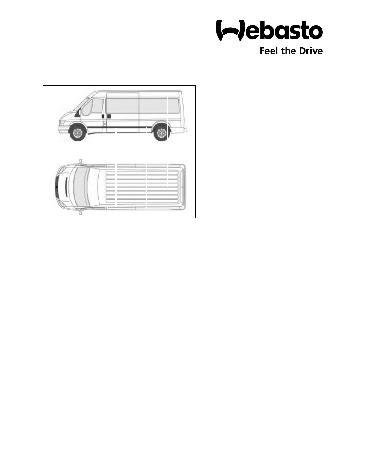
Webasto Ford Transit User manual

Transit London
Extreme Climate
Chassis-Mounted Condenser
Legend
1 London HVAC Unit Assembly
2 Coolant Valve
3CoolantPump
Special Tools
– Oetiker pliers (Webasto P/N 5012954A)
– Rivnut installation tool
– Hole saw kit
– Refrigerant recovery and recharging machine
– Weather-Pack/Metri-Pack crimping tool 12085270
1
2
3
Ford Transit
2015 - 2019
3.5 and 3.7 Liter Engines
148” wheelbase - All Roof Heights
For kit 5013292A
Special instructions for these models
Part locations may differ slightly dependent on
the vehicle-specific configuration.
DOC P/N 5013295A KIT P/N 5013292A Printed in USA Webasto N.A., Inc.

2
London Ford Transit
– Installation and repair of Webasto heating and cooling systems requires special
Webasto training, technical information, special tools and special equipment.
– NEVER attempt to install or repair Webasto heating or cooling system unless you
have the proper certifications, technical skills, tools, and equipment required to
properly complete the necessary procedures.
– ALWAYS carefully follow Webasto installation and repair instructions and heed all
WARNINGS.
– Webasto rejects any liability for problems and damage caused by the system being
installed by untrained personnel.

Ford Transit London
3
Kit CoTable of Contentsntents
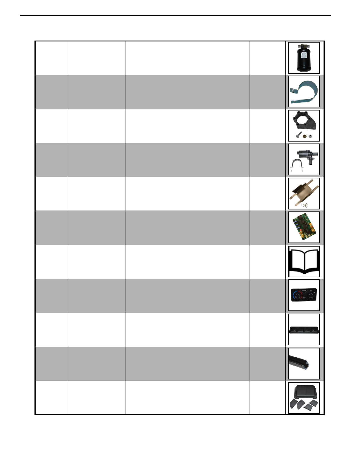
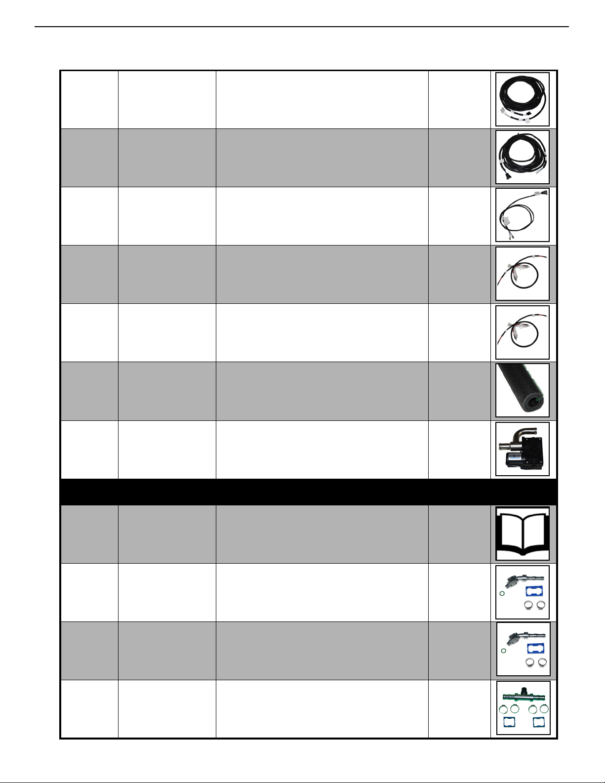
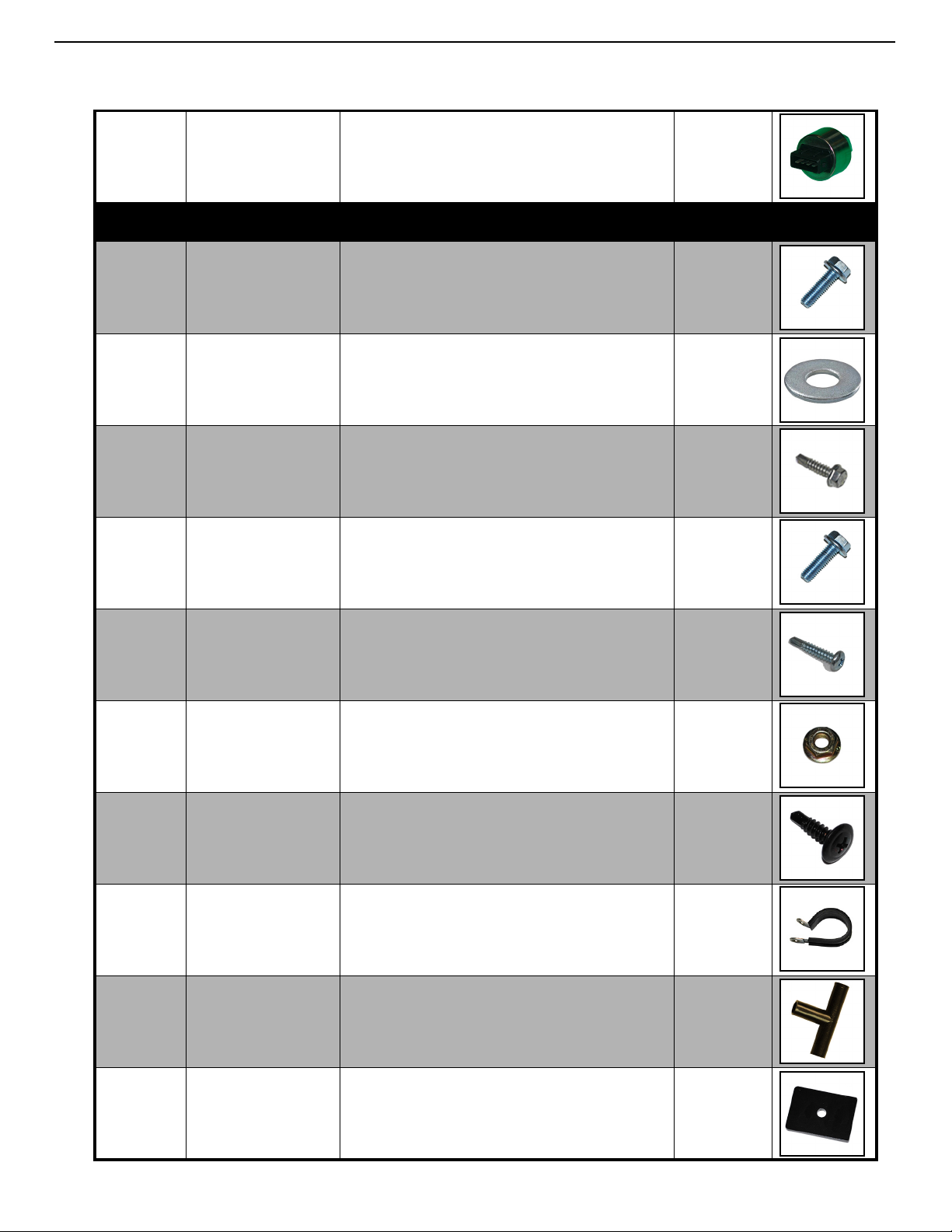
Kit Contents with Part Numbers . . . . . . . . . . . . . . . . . . . . . . . . . . . . . . . . . . . . . . . 4
INTRODUCTION . . . . . . . . . . . . . . . . . . . . . . . . . . . . . . . . . . . . . . . . . . . . . . . . . . 11
1.0 General Service and Safety Precautions . . . . . . . . . . . . . . . . . . . . . . . . . . 11
1.1 Refrigerants and Other Chemicals . . . . . . . . . . . . . . . . . . . . . . . . . . . . . 11
1.2 System Flushing, Purging, and Pressure Testing for Leaks . . . . . . . . . . . . 11
1.3 Scope . . . . . . . . . . . . . . . . . . . . . . . . . . . . . . . . . . . . . . . . . . . . . . . . . . . 12
1.4 Applicability of Manual . . . . . . . . . . . . . . . . . . . . . . . . . . . . . . . . . . . . . 12
1.5 Meaning of Warnings, Cautions and Notes . . . . . . . . . . . . . . . . . . . . . . 12
1.6 Safety . . . . . . . . . . . . . . . . . . . . . . . . . . . . . . . . . . . . . . . . . . . . . . . . . . 13
1.7 Legal Provisions for Installation . . . . . . . . . . . . . . . . . . . . . . . . . . . . . . . . 13
1.8 Prohibition on Venting . . . . . . . . . . . . . . . . . . . . . . . . . . . . . . . . . . . . . . 13
Vehicle and kit preparation . . . . . . . . . . . . . . . . . . . . . . . . . . . . . . . . . . . . . . 15
London HVAC Unit Installation . . . . . . . . . . . . . . . . . . . . . . . . . . . . . . . . . . . . . . 15
General References . . . . . . . . . . . . . . . . . . . . . . . . . . . . . . . . . . . . . . . . . . . . . . . 15
Electrical Installation . . . . . . . . . . . . . . . . . . . . . . . . . . . . . . . . . . . . . . . . . . . . . . 20
Wiring Harness Layout . . . . . . . . . . . . . . . . . . . . . . . . . . . . . . . . . . . . . . . . . 20
Extreme Board Layout . . . . . . . . . . . . . . . . . . . . . . . . . . . . . . . . . . . . . . . . . 21
A/C Hose Crimping . . . . . . . . . . . . . . . . . . . . . . . . . . . . . . . . . . . . . . . . . . . . . . . 30
Hose Installation . . . . . . . . . . . . . . . . . . . . . . . . . . . . . . . . . . . . . . . . . . . . . . . . . 32
A/C Hose Installation . . . . . . . . . . . . . . . . . . . . . . . . . . . . . . . . . . . . . . . . . . 34
Heater Hose installation. . . . . . . . . . . . . . . . . . . . . . . . . . . . . . . . . . . . . . . . 36
Initial Start . . . . . . . . . . . . . . . . . . . . . . . . . . . . . . . . . . . . . . . . . . . . . . . . . . . . . . 40
A/C System: . . . . . . . . . . . . . . . . . . . . . . . . . . . . . . . . . . . . . . . . . . . . . . . . . 40
Coolant System: . . . . . . . . . . . . . . . . . . . . . . . . . . . . . . . . . . . . . . . . . . . . . 40
Wiring Diagram . . . . . . . . . . . . . . . . . . . . . . . . . . . . . . . . . . . . . . . . . . . . . . . . . . 42
NEO 2 Extreme Kit . . . . . . . . . . . . . . . . . . . . . . . . . . . . . . . . . . . . . . . . . . . . 42
Extreme Board . . . . . . . . . . . . . . . . . . . . . . . . . . . . . . . . . . . . . . . . . . . . . . . 43

4
London Ford Transit
Item
Number Part Number Description Quantity
1 5011500A HVAC KIT LONDON 12V W-THERMO-
STAT 1
25011595A BRACKET - TRANSIT LONDON 1
3 62U00025459C CONDENSER - UNDERCHASSIS 1
45011825A BRACKET RDR UBC TRANSIT 1
5 5011824A BRACKET - SUPPORT RL UBC TRANSIT 1
65011822B BRACKET - SUPPORT CONDENSER -
FRONT 1
7 5011823A BRACKET - SUPPORT UBC TRANSIT 3
85011821A BRACKET - ANGLE SUPPORT - REAR 1
9 5013295A MANUAL - INSTALLATION 1
10 5011082C WARRANTY STATEMENT 1
Kit Contents

Ford Transit London
5
11 62017067A FILTER / DRYER R134-A 1
12 62036025D BRACKET - FILTER / DRYER 1
13 9027035A BAG - BRACKET U4847 1
14 1317523A CIRCULATION PUMP - U4847 1
15 5012655A BRACKET KIT - RELAY BOARD 1
16 5012514A RELAY BOARD HVAC EXTREME W/
LABEL 1
17 5010740A LABEL - SERIAL NUMBER 1
18 5012813A CONTROLLER - NEO 2 HVAC 1
19 6290321660B DIFFUSER 1
20 5013072A BAG - CABLE TIES AND TRIM 1
21 62U003AA093A COVER - EVAPORATOR 1

6
London Ford Transit
22 5013213A HOSE - REFRIGERANT -6 X 11M 1
23 5013159A HOSE - REFRIGERANT -8 X 6M 1
24 5013168A HOSE - REFRIGERANT -10 X 14M 1
25 5013225A HOSE HEATER 0.75 ID GATES BLUE STRIPE
4M 1
26 503221A HOSE HEATER 5/8 INCH ID 21M 1
27 5012587A WIRE HARNESS - T-STAT or LOW PRESSURE
SWITCH - 8600mm 2
28 5012948A WIRE HARNESS - HEATER CONTROL
EXTENSION SEALED 1
29 5012643A WIRE HARNESS - COMPRESSOR -
12,000mm 1
30 5012429A WIRE HARNESS - LP-HP SWITCH 5,900mm 1
31 5012584A WIRE HARNESS - CONDENSER FAN 2
32 5012883A WIRE HARNESS - EXTREME BOARD 1

Ford Transit London
7
33 5012876A WIRE HARNESS - BLOWER - 5500-
8100mm 1
34 5012880A WIRE HARNESS - NEO ADAPTER 1
35 5010321A WIRE HARNESS - COOLANT PUMP 1
36 5012447A BATTERY CABLE - POWER 1
37 5012570A BATTERY CABLE - GROUND 1
38 5011556A INSULTATION HOSE 1
39 6241258A COOLANT VALVE 1
5013294A BAG - AC COMPONENTS
40 5011771A LABEL - REFRIGERANT CHARGE 1
41 5011028B FITTING REFRIGERANT 45 -06THD -06HOSE 1
42 5011029B FITTING REFRIGERANT 45 -08THD -08HOSE 1
43 5011244B SPLICER IN LINE -10HOSE WITH PORT 1

8
London Ford Transit
44 5011005B FITTING REFRIGERANT 90 -12TUBE-O -
10HOSE 1
45 5011008B FITTING REFRIGERANT 90 -06THD -06HOSE 1
46 5011231B SPLICER IN LINE -08HOSE WITH PORT 1
47 5011030B FITTING REFRIGERANT 45 -10THD TO -10H 1
48 5011010B FITTING REFRIGERANT 90 -08THD -08HOSE 1
49 5011232B SPLICER IN LINE -10HOSE WITH PORT 1
50 5011212B FITTING REFRIGERANT 180 -06THD -
06HOSE 1
51 5011002A FITTING REFRIGERANT 90 -6CONN -6HOSE 1
52 5013071A BAG - TXV PLATE 1
53 5013253A ANTI-CONDENSATION TAPE 1
54 6233268A BAG - PRESSURE SWITCH 1

Ford Transit London
9
55 62043118A LOW-PRESSURE / HIGH-PRESSURE SWITCH 1
5013293A BAG - HARDWARE PARTS
56 905163Z BOLT HEX M8-1.25 6
57 902713Z WASHER FLAT 0.3125 x 0.75 6
58 5011487A SCREW SELF DIRLLING 0.25 X 1 INCH 10
59 5001321A BOLT HFH M6-1.0 6g x 20 11
60 902006Z SCREW SELF DRILLING 10-16ST x 1 5
61 5001322A NUT HEX FLANGE SERRATED M6-1 6H
8.8 8
62 5011593A SCREW SELF DRILLING - BLACK 7
63 21499A TUBE CLAMP 1
64 629069011A TEE DRAIN HOSE 12MM OD 1
65 5011594A THREADED PLATE M8X1.25 4

10
London Ford Transit
66 PPC301028A P-CLIP WITH RUBBER 60DIA 9
67 50000039A SCREW SELF DRILLING 0.25-14ST X 1.5 1
68 5001301A RIVET NUT FLUSH M6-1.0 4
69 5013178 BAG - ELECTRICAL SMALL PARTS 1
70 5013291A BAG ATO FUSE 20AMP 2 PIECES 1
71 5013476A SCREW CROSS RECESS M4x14 6
72 5012013A NUT NYLOCK M4-0.7 6
5013082A BAG - COOLANT SMALL PARTS
73 5011861A CLAMP SPRING BAND 22mm 12
74 5011862A CLAMP SPRING BAND 27mm 4
75 5012117A TEE COOLANT 19-16mm 2

Ford Transit London
11
INTRODUCTION
1.0 General Service and Safety Precautions
WARNING
Never service, repair, or troubleshoot this system unless you are a professional air conditioning/refrigeration service per-
son. Improper servicing can lead to serious injury or death from fire, electric shock, or explosion.
Refrigeration and air conditioning devices are extremely complicated by nature. Servicing, repairing, and
troubleshooting these products should be done only by those with the necessary knowledge, training, and equipment.
1.1 Refrigerants and Other Chemicals
Contact with refrigerant, mixtures of refrigerant and oil, or other chemicals can cause a variety of injuries including burns
and frostbite. For example, if refrigerant contacts skin or eyes it can cause severe frostbite. Also, in the event of a
compressor motor failure, some refrigerant and oil mixtures can be acidic and cause chemical burns.
To avoid injury, wear appropriate protective eye wear, gloves, and clothing when servicing an air conditioning or
refrigeration system. Refer to your refrigerant supplier for more information.
If refrigerant or mixtures of refrigerant and oil come in contact with skin or eyes, flush the exposed area with water and
get medical attention immediately.
1.2 System Flushing, Purging, and Pressure Testing for Leaks
Failure to properly flush, purge, or pressure test a system for leaks can result in serious injury or death from explosion, fire
or contact with acid-saturated refrigerant or oil mists.
Webasto recommends that the system be serviced using a flush and purge station such as a Robinair®
unit or similar equipment designed for R134a refrigerant systems.
Follow these precautions when flushing/purging a system or pressure testing a system for leaks:
• Use flushing products according to the manufacturer’s instructions.
• To purge a system, use only dry nitrogen.
• When pressure testing for leaks, use only
• regulated dry nitrogen or dry nitrogen plus trace amounts of the serial label refrigerant, in this case, R134a.
• When purging or pressure testing any refrigeration or air conditioning system for leaks, never use air, oxygen or
acetylene.
• Oxygen can explode on contact with oil.
• Acetylene can decompose and explode when exposed to pressures greater than approximately 15 PSIG.
• Combining an oxidizing gas, such as oxygen or air, with an HCFC or HFC refrigerant under pressure can result in
a fire or explosion.
• Use a pressure regulating valve and pressure gauges.
Commercial cylinders of nitrogen contain pressures in excess of 2000 PSIG at 70°F. At pressures much lower than 2000
PSIG, compressors can explode and cause serious injury or death. To avoid over pressurizing the system, always use a
pressure regulating valve on the nitrogen cylinder discharge. The pressure regulator must be able to reduce the pressure
down to 1 or 2 PSIG and maintain this pressure. The regulating valve must be equipped with two pressure gauges:
• one gauge to measure cylinder pressure, and
• one gauge to measure discharge or down-stream pressure.
76 5013547A COUPLER REDUCER 3/4 X 5/8 PLASTIC 1
77 5012120A BLEEDER VALVE OD 16mm 1

12
London Ford Transit
In addition to a pressure regulating valve and gauges, always install a pressure relief valve. This can also be a frangible disc
type pressure relief device. This device should have a discharge port of at least 1/2” MPT size. The valve or frangible disc
device must be set to release at 175 PSIG.
• Do not pressurize the system beyond 150 PSIG field leak test pressure. When field testing a system for leaks, 150
PSIG is adequate test pressure.
• Disconnect nitrogen cylinder and evacuate the system before connecting the refrigerant container. Disconnect the
nitrogen cylinder and release the pressure in the system before connecting a refrigerant container to the system. The
higher pressure gas in the system can explode the refrigerant container.
1.3 Scope
These non-binding installation instructions are intended to support trained or certified dealers, and personnel in the installa-
tion of the Webasto London-series HVAC unit. Provided these instructions are followed properly and all options listed in the
parts breakdown are installed, this system will provide supplemental heating and cooling.
1.4 Applicability of Manual
These non-binding installation instructions apply to the make/model listed on the front cover of this installation manual.
Due to optional equipment, there may be build variations between this installation manual and the vehicle you are working
on. Technical modifications that differ from the instructions set forth exclude all liability claims. Acknowledged engineering
conventions must be observed for the installation work. Carefully read all documentation prior to installation.
CAUTION
Location of the Webasto provided components, wiring and control devices are important for proper operation. Failure to
comply with the installation instructions provided may result in poor operation or damage to the Webasto unit, the vehicle,
or vehicle components.
Non-compliance with the installation instructions and information contained therein will void the warranty. The same
applies for repairs performed by untrained personnel and repairs not using original equipment spare parts.
1.5 Meaning of Warnings, Cautions and Notes
WARNING:
This heading is used to highlight that non-compliance with instructions or procedures may cause injuries or lethal accidents
to personnel.
CAUTION:
This heading is used to highlight that non-compliance with instructions or procedures may cause damage to equipment.
NOTE:

Ford Transit London
13
This heading is used to highlight and draw specific attention to information.
1.6 Safety
All relevant state and provincial regulations, if any, governing the installation of this device must be observed! The gen-
eral safety regulations for the prevention of accidents and the relevant operating safety instructions must be observed at
all times.
1.7 Legal Provisions for Installation
EPA regulations stipulate that all vehicles requiring the removal of refrigerants be serviced by a certified technician under
section 608 of the Clean Air Act and that all refrigerant be reclaimed and recycled.
Vehicle operation must not be impaired due to any Webasto installed components. All power circuits must be fused with
an appropriate fuse or circuit breaker.
1.8 Prohibition on Venting
Section 609 of the Clean Air Act prohibits individuals from intentionally venting ozone-depleting substances used as
refrigerants (generally CFCs and HCFCs), and their substitutes (such as HFCs) into the atmosphere while maintaining, ser-
vicing, repairing, or disposing of air-conditioning or refrigeration equipment.

14
London Ford Transit
Parts needed for the installation of the London HVAC Unit and related components:
Item
Number
Part Number Description Quantity
65 5011594A THREADED PLATE M8X1.25 4
2 5011595A BRACKET - TRANSIT LONDON 1
56 905163Z BOLT HEX M8-1.25 8
15011500A HVAC KIT LONDON 12V W-THERMOSTAT 1
39 6241258A COOLANT VALVE 1
63 21499A TUBE CLAMP 1
59 5001321A BOLT HFH M6-1.0 6g x 20 7
57 902713Z WASHER FLAT 0.3125 x 0.75 5
61 5001322A NUT HEX FLANGE SERRATED M6-1 6H 8.8 3
20 5013072A BAG - CABLE TIES AND TRIM 1
15 5012655A BRACKET KIT - RELAY BOARD 1
16 5012514A RELAY BOARD HVAC EXTREME W/LABEL 1
58 5011487A SCREW SELF DIRLLING 0.25 X 1 INCH 4
67 50000039A SCREW SELF DRILLING 0.25-14ST X 1.5 1
13 9027035A BAG - BRACKET U4847 1
14 1317523A CIRCULATION PUMP - U4847 1
3 62U00025459C CONDENSER - UNDERCHASSIS 1
65011822B BRACKET - SUPPORT CONDENSER - FRONT 1
85011821A BRACKET - ANGLE SUPPORT - REAR 1
71 5013476A SCREW CROSS RECESS M4x14 6
72 5012013A NUT NYLOCK M4-0.7 6
68 5001301A RIVET NUT FLUSH M6-1.0 2
11 62017067A FILTER / DRYER R134-A 1
12 62036025D BRACKET - FILTER / DRYER 1
55 62043118A PRESSURE SWITCH - 3 LEVEL 1
45011825A BRACKET RDR UBC TRANSIT 1
75011823A BRACKET - SUPPORT UBC TRANSIT 3
55011824A BRACKET - SUPPORT RL UBC TRANSIT 1

15
Ford Transit
Vehicle and kit preparation
Refer to the manufacturer’s instructions as
necessary:
• Remove the driver’s seat.
• Remove the battery.
• Remove the overhead package tray.
• Remove the battery tray.
• Remove the upper trim from the b- through e-pillars on the left side.
• Install the auxiliary A/C compressor.
1. Install the A/C compressor and mounting kit.
London HVAC Unit Installation
2. Insert the four threaded mounting plates
(65) in the locations as shown.
3. Install the mounting bracket (2, 56) and
London HVAC unit (1).
General References
• The locations of the components outlined in the manual are for reference only. If alternate locations re used the
wiring harness cannot be extended.
• Bare sheet metal, for example around drilled holes, must be treated with anti-corrosive coating.
• Secure hoses, cables and wiring harnesses with cable ties and fit protective hoses around them at chafing
points.
• Fit edge protectors (split fuel hose, grommet, split-loom, etc.) to sharp edges.
• Replace hose clamps as necessary. Hose clamps should be inspected before re-use. Look for damage to the
screw and to the band due to fatigue, corrosion, or improper installation.
• Some components pictured in this manual are prototype parts. Production parts may appear different.

16
London Ford Transit
4. Mount the coolant valve (39) near the left-
rear wheel using a p-clip (63) and an M6 bolt
and nut (59, 57, 61).
NOTE: Alternate method: drill two 2-inch
holes in the location shown and install
edge trim to protect against chaffing.
5. In front of the left-rear wheel, between the
inner and outer body panels, drill two 1 3/4
inch (45 millimeters) holes, five inches (127
millimeters) apart. Remove the material
between the holes and protect the cut edge
(20) against corrosion and wire chafing.
NOTE: The location of the extreme board is
not critical. Consider the best location for
installation and future service.
6. Install the extreme board and bracket (15, 16,
58) on the left side of the vehicle, along the
top of the wall.

17
Ford Transit London
NOTE: Alternate method: drill two 2-inch
holes in the location shown and install edge
trim to protect against chaffing.
7. Drill two 1 3/4 inch (45 millimeters) holes in
front of the left-rear wheel, similar to
previously done. Install edge protection
around the cut hole and protect against
chaffing.
8. Using the 1/4 in. X 1 1/2 in. self-tapping
screw (67) and coolant pump mount, secure
the coolant pump to the chassis outrigger
next to the fuel tank (13, 14).
9. Expand the 6 existing holes on the condenser
(3) to 4mm. Install the condenser
reinforcement brackets (6, 8) on the
condenser using 6 M4 bolts and nuts (71,
72).

18
London Ford Transit
10. Install the filter/dryer in the filter/dryer
mounting clamp (11, 12). Loosely install the
trinary switch (55) in the filter/dryer.
XXX
11.Install the filter/dryer assembly and the filter/
dryer bracket (4, 59). Use the existing
threaded holes in the chassis to mount the
bracket (56) Tighten the trinary switch.
NOTE: There are three right-angle con-
denser mounting brackets. The ‘long side’
of the bracket attaches to the condenser
assembly.
12. Loosely mount the three right angle
condenser mounting brackets (7, 59, 61) and
the straight bracket (5, 59, 61) to the
condenser.

19
Ford Transit London
NOTE: The condenser is installed on the left
side of the vehicle next to the fuel tank.
13. Hold the condenser in place and mark the
four mounting hole locations.
XXX
NOTE: In some cases you will only have to
drill three holes. One may already have the
appropriate threaded insert installed.
14. Drill four 3/8 inch holes and install the
threaded inserts (68) using an appropriate
tool.
NOTE: The A/C hose is shown installed for
clarity.
NOTE: The angled side of the bracket is
nearest the A/C fitting to prevent interfer-
ence between the bracket and the fitting.
15. Install the condenser assembly (59).

20
London Ford Transit
Electrical Installation
Refer to this graphic for electrical connections as needed.
1 Battery 12V power 8 Thermostat
2 Ignition ON 12V power 9 Compressor
3 Battery ground 10 Heat switch (NEO 3 only - goes to blower pin C) #
4 Blower motor connection at evaporator assembly 11 AC switch (NEO 2/3 - goes to AC blower pin C)
5 Blower motor connection at controller 12 AC swtich - extreme system only *
6 Coolant pump 13 Condenser fan connection at condenser *
7 Coolant valve 14 Condenser fan connection at extreme board *
# not used in this kit. Insulate and protect the wire * Used only in Extreme systems
Table of contents