Webasto Diavia PORDOI 3000 User manual
Codice / Code: 62U003FF110EC
Istruzioni di montaggio
Instructions pour le montage
Fitting instructions
Einbauanleitungen
Instrucciones de montaje
PORDOI
3000 "R134a"
Via Nobili, 2 40062 Molinella C.P. 69 (Bologna) - Italy
WEBASTO THERMO & COMFORT ITALY S.r.l.

DESCRIZIONE SIMBOLOGIA UTILIZZATA / DESCRIPTION DE LA SYMBOLOGIE UTILISÉE
DESCRIPTION OF SYMBOLS USED / BESCHREIBUNG DER VERWENDETEN SYMBOLIK
DESCRIPCIÓN DE LOS SIMBOLOS UTILIZADOS
Riferimento a figura / Référence à la figure / See figure
In Bezug auf Abbildungen / Referencia a la figura
Riferimento a componenti di fornitura / Référence aux composants de la fourniture
See supplied components / Bezug auf Gelieferte Einbauelemente
Referencia a los componentes de abastecimiento
Riferimento a posizione schema elettrico / Référence à la position du schéma électrique
See position in wiring diagram / In Bezug auf Position im Schaltschema
Referencia a la posición del esquema eléctrico
1
1
- Lubrificare tutti i raccordi e gli O.R. con il nuovo olio
refrigerante prima di collegarli
- Graisser tous les raccords et les O.R. avec le nuve-
au huile réfrigérant avant de les raccorder
- Forare
- Percer
- To drill
- Durchbohren
- Taladrar
- Tagliare con utensile appropriato al materiale
- Couper à l’aide d’outil approprié
- Cut with a device suitable for the material
- Mit dem Material entsprechendem Werkzeug
schneiden
- Cortar con herramienta apropiada al material
- Per avvitare a fondo o allentare i raccordi tubi gas usare due
chiavi per bilanciare coppia di torsione
- Pour visser à fond ou desserrer les raccords des tuyaux gaz, uti-
liser le deux clés pour équilibrer le couple de torsion
-Lubricate all fittings and O-rings with new refrigerant oil before con-
necting them
- Alle Verbindungsstücke und OR-Ringe vor deren Verbindung mit
dem neuen Kühlmittellöl ölen
- Lubrificar todos los empalmes y los O.R. con el nuevo aceite refri-
gerante antes de conectarlos
- When tightening or loosening the fittings of the gas pipes, use two wren- ches
to equilize the torsion couple
- Um die Verbindungsstücke der Kältemittelschläuche gleichmäßig festzu-
schrauben oder zu lockern, zwei Schlüssel für das Verschraubungspaar
verwenden
- Para enroscar a fondo o aflojar los empalmes tubos gas se deben usar dos lla-
ves para balancear el par de torsión
- Stagnare
- Étamer
- Tin
- Verzinnen
- Estañar
- Spianare
- Niveler
- Flatten out
- Richten
- Nivelar
- Tagliare con utensile a lama calda
- Couper à l'aide d'un outil à lame chaude
- Cut using the tool with heated blade.
- Mit Schweißmesserwerkzeug schneiden
- Cortar con útil a hoja caliente
1-
1A
3
Pos. ITALIANO FRANÇAIS ENGLISH DEUTSCH ESPAÑOL
61 Gruppo refrigerante Groupe réfrigérant Refrigeration unit Kühlereinheit Grupo refrigerante
61.1 Convogliatore
elettroventole Convoyeur
ventilateurs Electric fan conveyor Elektrogebläse
Luftförderer Transportador
electroventiladores
61.2 Copertura tubo
scarico condensa
Couverture tuyau
écoulement des
condensations
Condensate drain
hose cover
Abdeckung des Kon-
denswasserabfluß-
schlauchs
Cobertura tubo
de descarga
condensación
61.3 Fustellato
anticondensa Plaque anti-buée Condensation-
proofing punch Gestanztes
Antikondenswasserteil Troquelado
anti-condensación
61.4 Fermo per fustellato Dispositif de blocage
pour plaque Fastener for punch Klemmen für Stanzteil Bloqueo para
troquelado
62 Sacchetto accessori Sachet accessoires Bag of accessories Säckchen mit
Zuberhörteilen Bolsita accesorios
63 Tubo scarico
condensa Tuyau d’écoulement
des condensations Condensate
drain pipe Kondenserwasserab-
lußschlauch Tubo descarga
condensación
66 Display comandi Display commandes Control display Steuerungsdisplay Display mandos
67 Supporto display Support display Display support Displayträger Soporte display
68 Impianto elettrico per
display comandi
Faisceau électrique
pour écran des
commandes Electrical system
for control display Elektrische Anlage
des Steuerungsdis-
plays Instalación eléctrica
paradisplaymandos
69 Staffa di supporto
rele’ Support relais Relay support Relais-Halterbügel Estribo de soporte
relé
70 Copri-relais Couvre-relais Relay cover Relais-Verkleidung Cubre-realais
71 Sacchetto accessori
porta comandi Sachet accessoires
porte commande Bag of control
panel accessories
Säckchen mit
Zusatzteilen der
Steuerungshalterung
Bolsita accesorios
porta mandos
72 Sede comandi Logement
commandes Control panel Steuerungssitz Caja mandos
73 Staffa di supporto
sede comandi Etrier support du
logement
commandes Control panel support
bracket Haltebügel des
Steuerungssitzes Abrazadera de
soporte caja mandos
74 Sede per tappo
coprivite Logement pour
bouchon couvre-vis Housing for screw
plug Sitz für
Schraubenabdeckung Caja para tapa cubre
tornillo
75 Tappo coprivite Bouchon couvre-vis Screw cover plug Schraubenabde-
ckung Tapa cubre-tornillo
76 Contenitore olio Révoir huile Oil tank Ölbehälter Contenedor aceite
78 Etichetta adesiva carica
gas R134a Etiquette adhésive
charge gaz R134a Gas R134a charge
sticker
Selbstklebende
Etiketten
Kühlmittelfüllung
R134a
Etiqueta adhesiva
carga gas R134a
79 Busta documenti Enveloppe
documentation Document case Document bag Bolsa documentos
82 Impianto elettrico
Diavia Frigo Faisceau électrique
Diavia Frigo Wiring system
Diavia Frigo Elektrische Anlage
Diavia Frigo Instalación eléctrica
Diavia Frigo
Fascetta a strappo Bride auto-bloquant Self-locking clamp Selbstsichernde
Schelle Banda
autobloqueante
4
Scopo e ambito
Il frigorifero può essere utilizzato come unità di refrigerazione del vano di carico solo per i veicoli di categoria N1 come defi-
nita nelle direttiva 2007/46/CE (Veicoli progettati e costruiti per il trasporto di merci, aventi massa massima non superiore a
3,5 t.).
Objectifs et champ d'application
Le groupe frigorifique embarqué peuvent être utilisées en tant que unité de réfrigération de compartiment à marchandises
seulement sur des véhicules des catégories N1 telles que définies par la directive 2007/46/CE (Véhicules conçus et construits
pour le transport de marchandises ayant un poids maximal ne dépassant pas 3,5 tonnes).
Scope and purpose
The cooling equipment can be used as a cargo space refrigeration unit on vehicle category N1 only, as defined by Directive
2007/46/EC (Vehicles designed and constructed for the carriage of goods and having a maximum mass not exceeding 3,5
tonnes).
Geltungsbereich und Zweck
Fahrzeugkühlaggregat zur Laderaumkühlung nur auf Fahrzeugen der Klasse N1 gemäß Richtlinie 2007/46/EG (Für die Gü-
terbeförderung ausgelegte und gebaute Kraftfahrzeuge mit einer zulässigen Gesamtmasse bis zu 3,5 Tonnen).
Aplicación y uso
Equipo de refrigeración en vehículos puedes ser utilizado por unidades de refrigeración del espacio de carga sólo para
vehículos de las categorías N1 con arreglo a la definición de la Directiva 2007/46/CE (Vehículos cuya masa máxima no supere
las 3,5 toneladas diseñados y fabricados para e transporte de mercancías).

5
Pos.
Descrizione
Description
Description
Beschreibung
Descripción
Codice
Code
Kode
Codigo
61 Gruppo refrigerante 0301176/1
61.1 Convogliatore
elettroventole 0322124/2
61.2 Copertura tubo
scarico condensa 0321878/1
61.3 Fustellato anticondensa 0701281/1
61.4 Fermo per fustellato 52459054/00
62 Sacchetto accessori 029925/0
63 Tubo scarico condensa 069855.2
66 Display comandi 0682513/5
67 Supporto display
68 Impianto elettrico per
display comandi 0282334/1
69 Staffa di supporto rele’ 0681260/0
70 Copri-relais 0361158/0
71 Sacchetto eccessori
porta comandi 029819/0
72 Sede comandi 0321892/0
73 Staffa di supporto
sede comandi 0682052/0
74 Sede per tappo
coprivite 069291/0
75 Tappo coprivite 069586/0
76 Contenitore olio 040595/1
78 Etichettaadesivacaricagas
(R134a) ETHDV00080/2
79 Busta documenti DDC003/2
MONTAGGIO GRUPPO REFRIGERANTE / POSE DU GROUPE REFRIGERANT
REFRIGERANT UNIT ASSEMBLY / EINBAU DER KÜHLEINHEIT
MONTAJE E INSTALACIÓN DEL GRUPO REFRIGERANTE
MATERIALE FORNITO / MATERIEL FOURNI / SUPPLIED MATERIAL / GELIEFERTES MATERIAL / MATERIAL ABASTECIDO
1A
61
61.1
63
68
67 6669 70 0282334/1
1.1A
76
62
78
79
71
74
75
73 72
61.2
61.3
61.4
6
Pos.
Descrizione
Description
Description
Beschreibung
Descripción
Codice
Code
Kode
Codigo
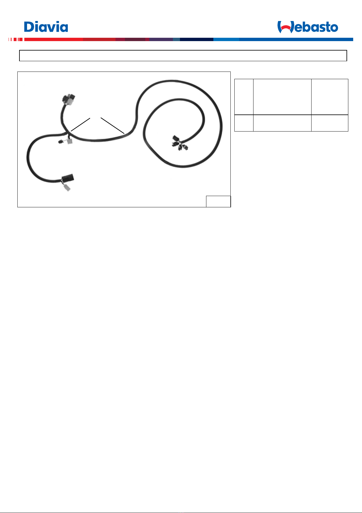
82 Impianto elettrico
Diavia Frigo 0282335/2
MATERIALE FORNITO / MATERIEL FOURNI / SUPPLIED MATERIAL / GELIEFERTES MATERIAL / MATERIAL ABASTECIDO
2A
82
0282335/2
7
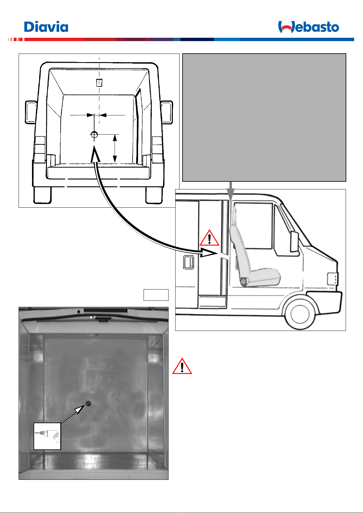
3A
35mm
600mm
(I) Forare la paratia di coibentazione con leggera inclinazione
(F) Percer la paroi d'isolation avec une légère inclination
(GB) Drill the insulation firewall at a slight angle
(D) Die Isolierungswand mit leichter Neigung bohren
(E) Perforar el mamparo de aislamiento con leve inclinación
80mm
(I)
VALIDO PER VEICOLI CON PARATIA ANTERIORE DELLA CELLA
FRIGORIFERA A RIDOSSO DEI SEDILI DELLA CABINA DI GUIDA.
(F)
VALABLE POUR LES VÉHICULES AYNT LA PAROI AVANT DE LA
CELLULE A GLACE CONTRE LES SIÈGES DE LA CABINE DE
CONDUITE.
(GB)
VALID FOR VEHICLES WHERE THE FRONT REFRIGERATION
CELL WALL IS SET AGAINST THE DRIVING CABIN SEATS.
(D)
GÜLTIG BEI FAHRZEUGEN MIT WAND VOR DER KÜHLZELLE
HINTER DEN SITZEN DER FÜHRERKABINE.
(E)
VÁLIDO PARA COCHES CON MAMPARO ANTERIOR DE LA CÁMARA DE
REFRIGERACIÓN JUNTO A LOS ASIENTOS DE LA CABINA DE
CONDUCCIÓN.
8
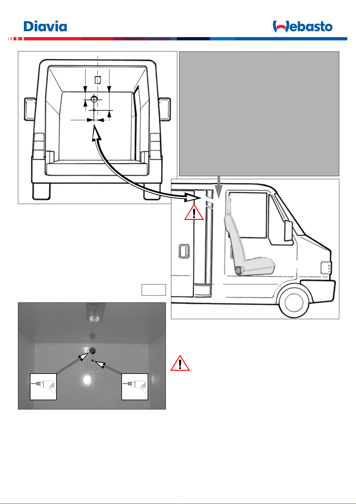
3.1A
35mm
200mm
(I) Forare la paratia di coibentazione con leggera inclinazione
(F) Percer la paroi d'isolation avec une légère inclination
(GB) Drill the insulation firewall at a slight angle
(D) Die Isolierungswand mit leichter Neigung bohren
(E) Perforar el mamparo de aislamiento con leve inclinación
80mm
80mm 24mm
(I)
VALIDO PER VEICOLI CON PARATIA ANTERIORE DELLA CELLA
FRIGORIFERA DISTANZIATA DAI SEDILI DELLA CABINA DI GUIDA.
(F)
VALABLE POUR LES VÉHICULES AYANT LA PAROI AVANT DE LA
CELLULE A GLACE ELOIGNÉE DES SIÈGES DE LA CABINE DE
CONDUITE.
(GB)
VALID FOR VEHICLES WHERE THE FRONT REFRIGERATION
CELL WALL IS SET AT A DISTANCE FROM THE DRIVING CABIN SEATS.
(D)
GÜLTIG BEI FAHRZEUGEN MIT WAND VOR DER KÜHLZELLE, VON DEN
SITZEN DER FüHRERKABINE ENTFERNT GELEGEN.
(E)
VÁLIDO PARA COCHES CON MAMPARO ANTERIOR DE LA CÁMARA DE
REFRIGERACIÓN SEPARADO DE LOS ASIENTOS DE LA CABINA DE
CONDUCCIÓN.

9
61.461.461.461.461.4
61.3
61.4
(I)
Posizionare il fustellato “61.3” in corrispondenza dello spigolo inferiore della batteria evaporante del gruppo Diavia Frigo, in modo che
risulti uniformemente sporgente di ~20mm, lungo tutto il lato di appoggio, come indicato nel dettaglio di figura. Bloccare il fustellato alla
batteria evaporante inserendo ad incastro i sei fermi forniti ”61.4” tra le alettature della batteria. Il definitivo posizionamento e il bloccaggio
del fustellato verrà garantito al momento dell’accoppiamento del gruppo evaporante al convogliatore aria.
(F)
Placer la plaque "61.3" à la hauteur de l'arête inférieure de la batterie d'évaporation du groupe Diavia Frigo, de telle sorte qu'elle dépasse
de façon uniforme de ~20mm, sur tout le côté d'appui, de la façon indiqué dans le détail de la figure. Bloquer la plaque à la batterie d'év-
aporation, en encastrant les six dispositifs de blocage fournis "61.4" entre les ailettes de la batterie. Le positionnement définitif et le blo-
cage de la plaque sont assurés au moment de l'accouplement du groupe d'évaporation au convoyeur d'air.
(GB)
Position the punch "61.3" on the lower edge of the Diavia Frigo unit evaporating battery so that it protrudes uniformly by ~20mm along
the entire contact edge as indicated in the inset in the figure. Lock the punch to the evaporating battery by snapping it in, between the
fins of the battery, on the six fasteners provided "61.4". Final positioning and securing of the punch is ensured when the evaporating unit
is coupled to the air conveyor.
(D)
Stanzteil "61.3" an untere Kante der Verdampferbatterie der Diavia Frigo Gruppe positionieren, sodass dieses Teil entlang der gesamten
Auflageseite, wie im Detail der Abbildung dargestellt gleichmäßig ~20mm Hervorsteht. Das Stanzteil an Verdampferbatterie befestigen
indem man die sechs gelieferten Klemmen "61.4" zwischen die Rippen der Batterie festklemmen. Die endgültige Positionierung und Be-
festigung des Stanzteils ergibt sich bei der Anpassung der Verdampfergruppe an den Luftförderer.
(E)
Colocar el troquelado "61.3" en correspondencia con la arista inferior de la batería evaporadora del grupo Diavia Frigo, de manera que
quede uniformemente saliente de ~20mm a lo largo de todo el lado de apoyo, como se indica en el detalle de la figura. Bloquear el tro-
quelado a la batería evaporadora introduciendo a encastre los seis bloqueos abastecidos "61.4" entre las aletas de la batería. La colo-
cación definitiva y la fijación del troquelado estarán garantizadas cuando el grupo evaporador se acople al transportador aire.
61.3
20mm
INSERIRE AD INCASTRO
INSERER PAR EMBOITEMENT
TO INSERT TO JOINT
EINKLEMMEN
INSERIR A ENCASTRE
61.4
61.3
4A
ELIMINARE
ELIMINER
DISCARD
ENTFERNEN
ELIMINAR
61.3
10
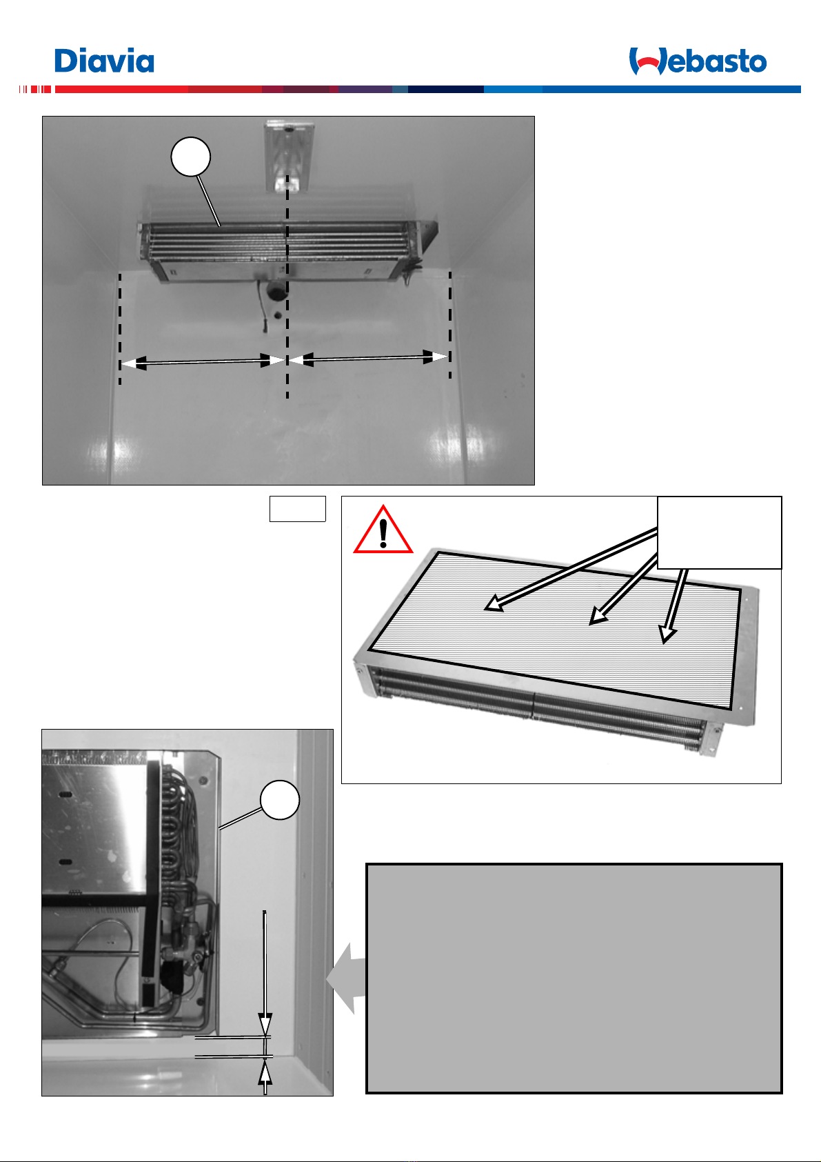
35mm
61
5A
61
== (I) Vedi anche figura seguente
(F) Voir aussi figure suivante
(GB) Also see the following figure
(D) Siehe auch folgende Abbildung
(E) Véase también figura siguiente
SILICONARE
METTRE DE LA SILICONE
COAT WITH SYLICONE
MIT SILIKON ABDICHTEN
SILICONAR
(I) Distanza consigliata dalla parete anteriore della cella
frigorifera.
(F) Distance conseilléedela paroi avantdelacellule à glace.
(GB) Suggested distance form the front wall of the
refrigeration cell.
(D) RatsamerAbstandvondervorderenWandderKühlzelle.
(E) Distancia aconsejada del mamparo de la cámara de
refrigeración.
11
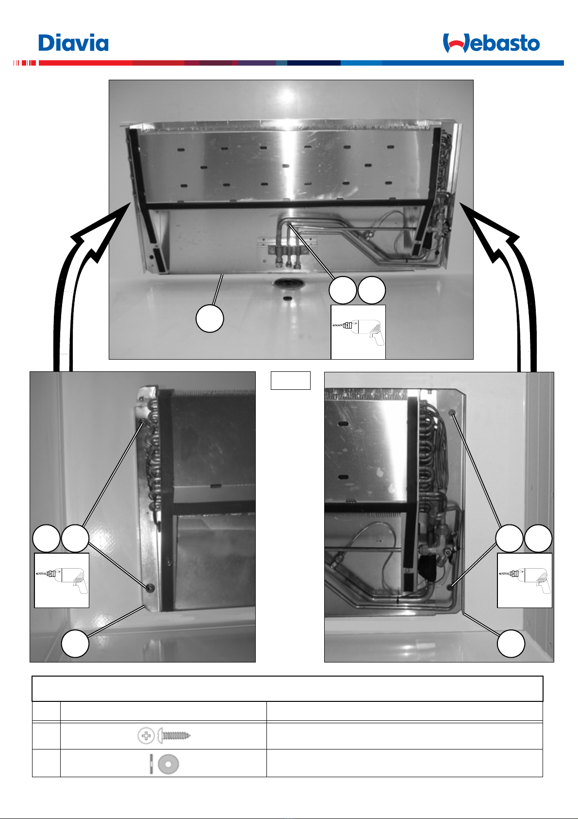
6A
61
ELEMENTI DI FISSAGGIO / PIECES DE FIXATION / FIXING PARTS
BEFESTIGUNGSELEMENTE / ELEMENTOS DE FIJACION
Pos. Tipologia / Typologie / Typology / Tipologie / Tipologia Descrizione / Description / Description / Beschreibung / Descripción
61.5 6 x 25
61.6 6 x 18 x 2 (INOX)
4,5mm
61.661.5
61
61.561.6
4,5mm
61
4,5mm
61.561.6
12
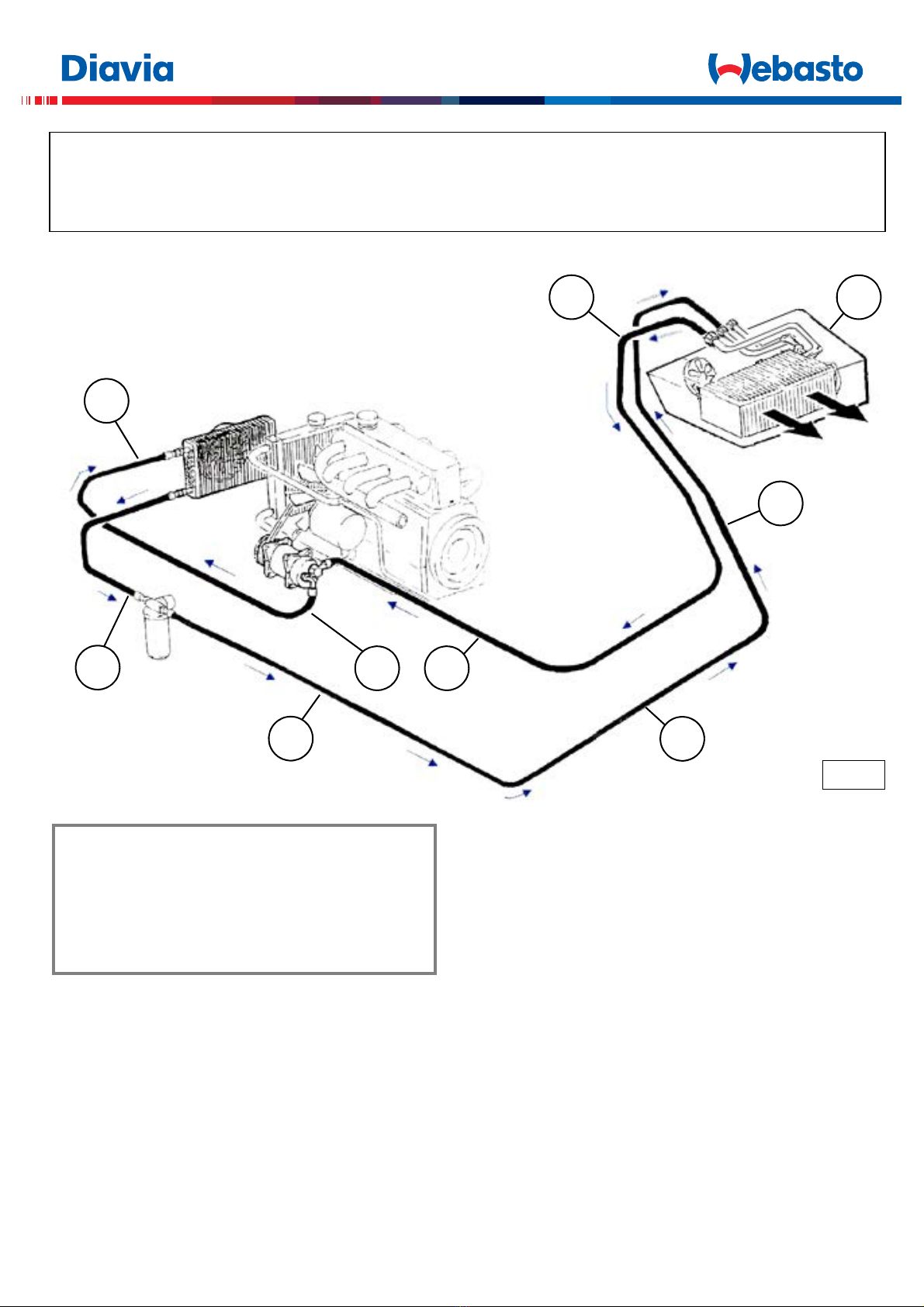
COLLEGAMENTO TUBI GAS - CIRCOLAZIONE FLUIDO REFRIGERANTE - INSTALLAZIONE COMPONENTI ELETTRICI
CONNEXION DES TUYAUX GAZ - CIRCULATION FLUIDE RÉFRIGÉRANT - INSTALLATION COMPOSANTS ÉLECTRIQUE
GAS HOSE CONNECTION - REFRIGERANT CIRCULATION - ELECTRICAL COMPONENT INSTALLATION
KÄLTEMITTELSCHLAUCHVERBINDUNG - KÜHLMITTELKREISLAUF - EINBAU DER ELEKTRISCHEN BAUTEILE
CONEXIÓN DE LOS TUBOS GAS - CIRCULACIÓN LÍQUIDO REFRIGERANTE - INSTALACIÓN DE LOS COMPONENTES ELÉCTRICOS
7A
61
5/16"
FE
1/2"
EC
5/16"
FE
1/2"
EC
13/32"
CC
5/16"
FE
5/16"
CF
13/32"
CC
(I) Componenti forniti nell’impianto base
(F) Composants fournis avec l'installation de base
(GB) Components supplied with the base kit
(D) Mit Grundausstattung geliefertes Material
(E) Componentes abastecidos con la instalación de base

13
8A
80mm
(I) Zona retrostante sedili
(F) Zone sous les sièges
(GB) Area behind the seats
(D) Bereich hinter den Sitzen
(E) Zona situada detrás los asientos
5/16"
FE
5/16"
FE
9A
63
63 1/2"
EC
1/2"
EC
80mm

14
10A
ELEMENTI DI FISSAGGIO / PIECES DE FIXATION / FIXING PARTS
BEFESTIGUNGSELEMENTE / ELEMENTOS DE FIJACION
Pos. Tipologia / Typologie / Typology
Tipologie / Tipologia Descrizione / Description / Description
Beschreibung / Descripción
69.1 4 x 12
Fascetta a strappo
3
63
63
69.1
69
69.1
82
5A
68
4
82
82
82
11
10-10A
11
10-10A
11
10-10A
3A
(I)
Impianto prolunga DIAVIA FRIGO fornito nell’impian-
to base.
(F)
Installation rallonge DIAVIA FRIGO fournie avec l'installation
de base.
(GB)
DIAVIA FRIGO extension supplied with base.
(D)
Mit Grundaustattung gelieferte Verlängerungskabelstrang
DIAVIA FRIGO.
(E)
Grupo extensible DIAVIA FRIGO abastecido con la instalación
de base.
5/16"
FE
1/2"
EC
5/16"
FE
1/2"
EC
82
81
15
11A
6361 82
5/16"
FE
61
1/2"
EC
16
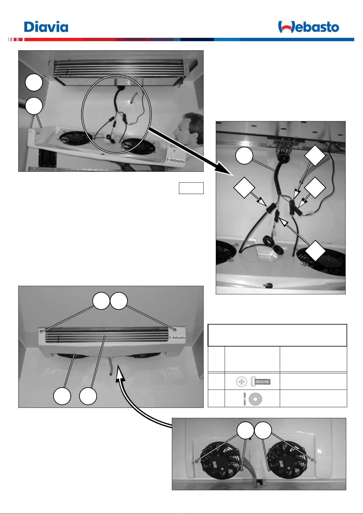
12A
61.1
61
61.161
61.861.7
ELEMENTI DI FISSAGGIO / PIECES DE FIXATION
FIXING PARTS / BEFESTIGUNGSELEMENTE
ELEMENTOS DE FIJACION
Pos. Tipologia / Typologie
Typology / Tipologie
Tipologia
Descrizione / Description
Description / Beschreibung
Descripción
61.7 M6x20 (INOX)
61.8 6,7x25 (INOX)
61.861.7
7D
82
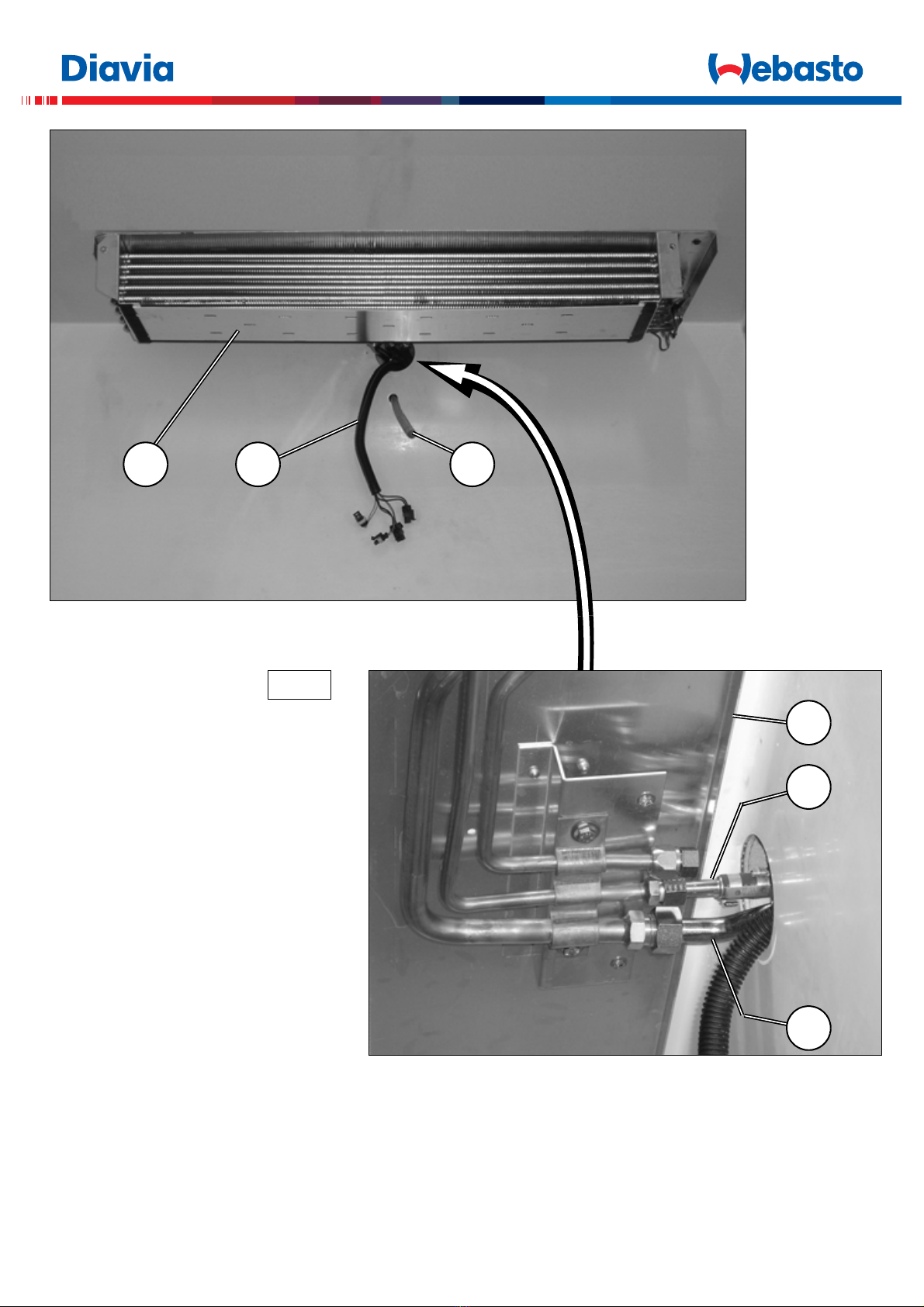
(I)
ATTENZIONE: sigillare il foro di ingresso nella cella
frigorifera, dei tubi gas e cavi elettrici, mediante poliu-
retano espanso o silicone.
(F)
ATTENTION: sceller le trou d'entrée à la cellule à gla-
ce, des tuyaux gaz et fils électriques, à l'aide de
polyuréthane expansé ou silicone.
(GB)
CAUTION: seal the hole through which the gas hoses and wires
enter the refrigeration cell with polyurethane foam or silicone.
(D)
ACHTUNG: die Eintrittsöffnung der Kältemittel schläuche und
der elektrischen Kabeln in die Kühlzelle, ist mit Polyurethan-
Schaumstoff oder mit Silikon abzudichten.
(E)
ATENCIÓN: sellar el orificio de entrada en la cámara de refri-
geración, de los tubos gas y de los cables eléctricos, mediante
espuma de poliuretano o silicón.
6A
6
7E

17
13A
61.2
63
ELEMENTI DI FISSAGGIO / PIECES DE FIXATION
FIXING PARTS / BEFESTIGUNGSELEMENTE
ELEMENTOS DE FIJACION
Pos.
Tipologia
Typologie
Typology
Tipologie
Tipologia
Descrizione
Description
Description
Beschreibung
Descripción
61.9 4 x 14 (INOX)
61.2
61
20mm
63
61.2
61
61.9
61.2
61
61.9

18
(D)
Einbau der im Armaturenbrett angepassten Display-Steuerung.
Die Anschlüsse der elektrischen Anlage "68" an Display-Steuerung "66" unter Befolgung des Schaltschemas im Anhang ausführen und mit
der Befestigung des Displays im Inneren der Führerkabine in dem vom Einbauer als angebrachten Bereich angesehene Position fortschrei-
ten (rechteckige Bohrung 29x71mm ausführen) Zur Befestigung die seitlichen Halterungen "67" verwenden, die mit dem Display mitgeliefert
wurden.
(E)
Instalación del Display mandos integrado en el tablero.
Efectuar las conexiones de la instalación eléctrica "68" al display mandos "66" siguiendo el esquema eléctrico adjunto y fijar el display al
interior de la cabina de conducción, en zona apropriada, a establecer por el instalador (efectuar orificio rectangular 29x71mm), utilizzando,
para bloquearlo, los soportes laterales "67", abastecidos junto al display.
66
68
1
3
(I)
Installazione del Display comandi integrato nel cruscotto.
Eseguire i collegamenti dell’impianto elettrico "68" al display comandi
"66" seguendo lo schema elettrico allegato e procedere al fissaggio del
display all'interno della cabina di guida, in zona appropriata, da stabilire
a cura dell'installatore (eseguire foro rettangolare 29x71mm), utilizzando
per il suo bloccaggio i supporti laterali "67", forniti unitamente al display.
(F)
Installation de l'Écran commandes incorporé dans le tableau de
bord.
Effectuer les branchements du faisceau électrique "68" à l'écran com-
mandes "66" selon le schéma électrique joint et procéder à la fixation de
l'écran à l'intérieur de la cabine de conduite, dans une zone appropriée
choisie par l'installateur (effectuer un trou rectangulaire de 29x71mm);
pour la fixation utiliser les supports latéraux "67", fournis avec l'écran.
(GB)
Installing the integrated Control
Display in the dashboard. Hook up
the supplied wiring system "68" to the
control display "66" following the indi-
cations in the enclosed wiring dia-
gram and securing the display in an
appropriate position inside the driving
cabin carefully determined by the in-
staller (prepare a 29x71mm rectan-
gular hole on site). Lock in place with
the side supports "67" provided with
the display.
67
66
14A
1

19
66
7268
73
75
75
75
74
74
74.2
74.1
74.1
74.2
74.3
74.3
67
67
1
15A
66
68
1
3
(I)
Installazione del Display comandi
sul cruscotto mediante utilizzo di
supporto.
Eseguire i collegamenti dell’impianto
elettrico "68" al display comandi "66",
inserendo i cavi attraverso il foro pre-
disposto sul supporto e seguendo le
indicazioni dello schema elettrico alle-
gato. Alloggiare il display all'interno
del supporto utilizzando per il suo
bloccaggio i supporti laterali "67", for-
niti unitamente al display. Abbinare al
supporto la staffa di fissaggio.
ATTENZIONE: per ragioni di sicu-
rezza, fissare il controllore sul cru-
scotto, nel lato a sinistra del
volante (lato destro per guida RHD).
ELEMENTI DI FISSAGGIO / PIECES DE FIXATION
FIXING PARTS / BEFESTIGUNGSELEMENTE
ELEMENTOS DE FIJACION
Pos.
Tipologia
Typologie
Typology
Tipologie
Tipologia
Descrizione
Description
Description
Beschreibung
Descripción
74.1 3,9 x 13
74.2 M4 x 16
74.3 4 x 16 x 1,5
Fascettaastrappo
20
Fig.15A
(F)
Installation de l'Écran commandes sur le tableau de bord au moyen d'un support .
Effectuer les branchements du faisceau électrique "68" à l'écran commandes "66", et introduire les fils à travers le trou situé sur le support
selon les indications du schéma électrique joint. Loger l'écran à l'intérieur du support; pour la fixation utiliser les supports latéraux "67",
fournis avec l'écran. Assembler l'étrier de fixation au support.
ATTENTION: Pour des raisons de sécurité, fixer le contrôleur sur le tableau de bord, sur le côté situé à gauche du volant (côté
droit pour conduite RHD).
(GB)
Installation of the Control Display in the dashboard using supports.
Hook up the supplied wiring system "68" to the control display "66" and pass the wires through the holes arranged on the support. Follow
the indications in the enclosed wiring diagram. Set the display inside the support and lock in place with the side supports "67" provided with
the display. Connect the securing bracket to the support.
CAUTION: For safety reason, fix the controlling device on the instrument panel, on the left side of the steering wheel (right side
for RHD driving).
(D)
Einbau der Display-Steuerung am Armaturenbrett unter Verwendung der Halterung.
Die Anschlüsse der elektrischen Anlage "68" an Kabel durch die vorhandene Öffnung an der Halterung unter Befolgung der Anleitungen
des Schaltschemas im Anhang einführen und Anschlüsse an Steuerungsdisplay "66" ausführen. Display im Inneren der Halterung unter-
bringen und mit den seitlichen gelieferten Halterungen "67" zusammen mit dem Display befestigen.
ACHTUNG: Aus Sicherheitsgründen ist das Kontrollgerät links vom Lenkrad am Armaturenbrett zu befestigen (rechten Seite für
RHD Fahren).
(E)
Instalación del Display mandos sobre el tablero mediante utilización de soporte.
Efectuar las conexiones de la instalación eléctrica "68" al display mandos "66" inserendo los cables a travès el orificio predispuesto sobre
el soporte y siguiendo las indicaciones del esquema eléctrico adjunto. Colocar el display al interior del soporte utilizzando, para bloquearlo,
los soportes laterales "67" abastecidos junto al display. Acoplar la abrazadera de fijación al soporte.
ATENCION: Por motivos de seguridad, fijar el controlador al salpicadero, en la parte izquierda del volante (lado derecho por RHD).
(I)
ATTENZIONE:
Terminate le fasi di montaggio dell’Impianto PORDOI, eseguire le operazioni di carica e di rabbocco olio, secondo le indicazioni riportate
nel manuale fornito con l’Impianto base; avviare l’impianto di refrigerazione ed impostare i valori delle temperature di esercizio, in base
all’esigenza dei prodotti trasportati, regolando il dispositivo elettronico di comando (66) secondo le indicazioni riportate nel libretto d’Uso
e seguendo le procedure di programmazione parametri illustrate nel manuale allegato al dispositivo elettronico di comando.
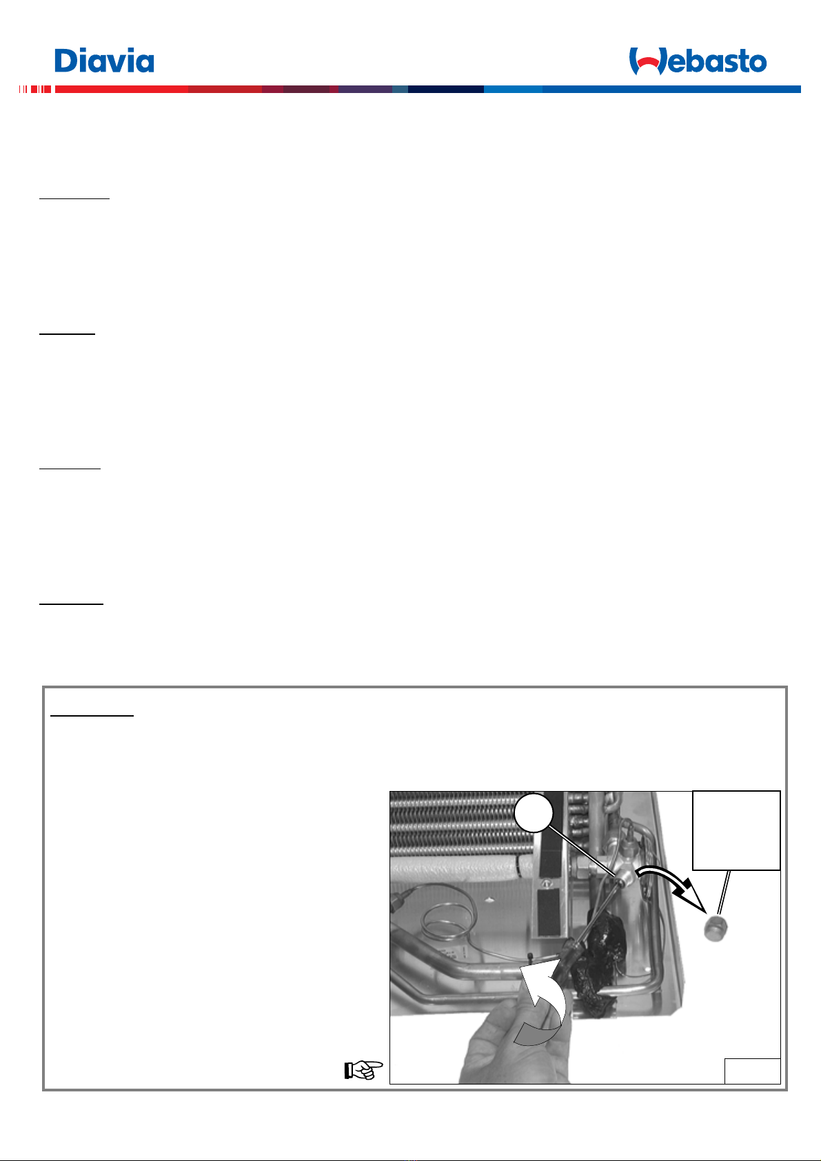
Mantenendo collegata la centralina di carica, è necessario
anche verificare la corretta registrazione del surriscaldamen-
to del refrigerante in uscita dall'evaporatore. L’operazione
consiste nell’avviare l’impianto di refrigerazione con un regi-
me di rotazione del motore di ~2000 giri/min. e controllare
che alla temperatura di utilizzo (ad esempio 5°C), la pressio-
ne di aspirazione sia maggiore o uguale a 0,5 bar.
In caso contrario è necessario diminuire il surriscaldamento
attraverso la rotazione antioraria (180° per ogni fase di rota-
zione) della vite di regolazione "V" della valvola di espansio-
ne, in modo da ottenere una pressione di aspirazione
adeguata.
N.B.
La mancata regolazione potrebbe procurare problemi di
affidabilità del compressore a causa di un’inadeguata lu-
brificazione.
16A
VRIMUOVERE
ENLEVER
REMOVE
ENTFERNEN
QUITAR
Table of contents
Other Webasto Refrigerator manuals


