rative When Mechanism
2. Switch contacts worn, dirty or broken.
(a) Clean contacts or replace. See "Speed
Equalization Switch Adjustment".
1. Damaged or worn cam and shaft assembly
(35A). (a) Replace.
ADJUSTMENTS
Pressure Pad And Lever Adjustments-
Cleaning, adjusting or replacing pressure pad
assembly and lever assemblies should be done in the
following manner:
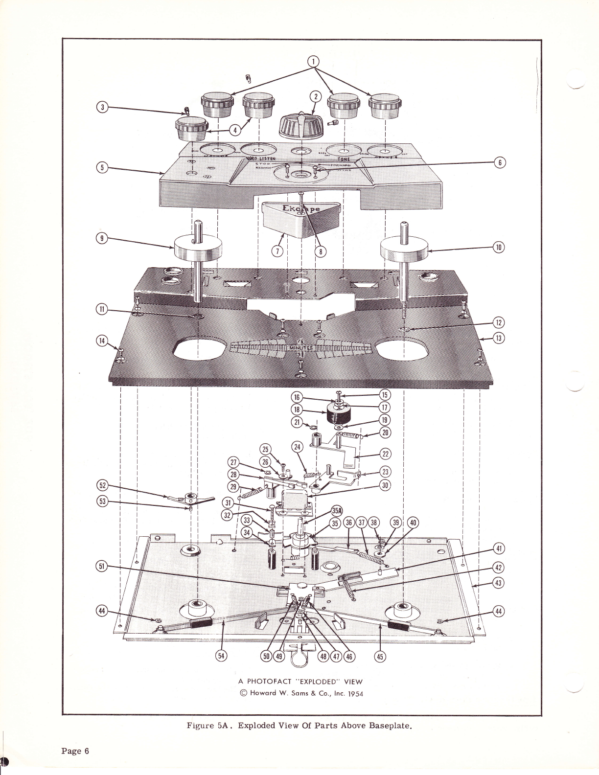
1. To adjustpressure padassembly(28), remove
back cover (5) and top panel (13). To remove
assembly f or cleaning, repair or adjustment,
remove spring (29) and retaining ring (2?). Ro-
tatethe pressurepad assemblyslightly counter-
clockwise and lift off. Reassemble in reverse
orderand lubricate (see "Lubrication"). Adjust
by turning cam and shaft assembly (35A) to "For-
ward" position and check to be sure pressure
pads engage groove of head properly.
NOTE: Be sure flat of pad presses against the erase
and record pole pieces. To adjust properly,
bend levers accordingly.
Improper Rewind Operation-
Ifthe unit doesnot perform the rewind operation
properly, check.as follows:
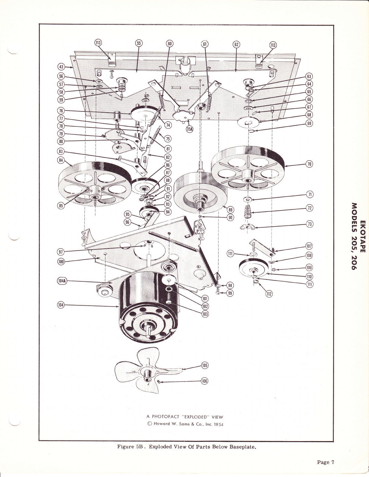
1. Adefectivemotorpulley(94) maybe the cause
of improper rewind. To replace a defective
motorpulleyassembly, remove the three mount-
ingscrews (103) from motor and plateassembly
(104). Carefully remove theassembly so as not
to damage the drive idler assemblies (?6 and 86).
Before removing the motor pulley measure and
note distance from hub to motor. Loosen the
twoAllen head set screws andremove themotor
pulley a.ssembly. Reassemble witha irew pulley
inreverse order. Be surepulley hub is correct
distance from motor as previously noted.
2. Adirty or defective supply reelshaft support
assembly (55) may be responsible for improper
rewind. To correctfaulty operation, clean, re-
pair or replace any damaged or worn parts.
Adjusting Brake Lever Assembly (45 and 54)-
If tape overruns from "Rewind" to "Stop" posi-
tion, adjust, clean or replace brake lever assembly
(45).
1. To ad just brake lever assembly (45), turn
camand shaft assembly (35A) to"Rewind" posi-
tion. Adjust either by bending the brake lever
assembly (45) or by slightly bending the stop on
mechanism panel just enough to clear the cup
disc on reel shaft (10). Clearance should not
exceed 1/64 inch. Adjust brake lever (45) so
that remote lever (51) returns to "Stop" posi-
tion. Check to be sure brake lever (54) on the
supply reel (9) is being held in its stop position
Page 10
by the remote lever assembly (51). If not, turn
camand shaftassembly (35A) to "Fast Forward"
andadjust brake lever assembly(54) as outlined
above. Before reassembly of top panel, thread
recorder with tape and checkunit for any further
trouble.
2. If tape overruns from "Fast Forward" to
"Forward", check operation of bral<e lever (54)
as explained in above paragraph with this ex-
ception; turn cam and shaft assembly (35A) to
"Fast Forward" position and adjust brake Iever
(54) on the supply reel (9). Check brake lever
(45) on the tale-up reel to be sure it is held in
its stop position by the remote lever assembly
(51). If not, turn cam and shaft assembly (35A)
to "Rewind" and adjust brake lever as covered
in above paragraph.
Adjusting Brake Arm Assembly (113)-
If af ter completing adjustments as covered in
"Adjusting Brake Lever Assembly", the overrun on
"Rewind" and "Fast Forward" is not corrected, re-
move the unit from the case and check as follows:
1. Check "Rewind" position first and adjust or
replace brake arm assembly (113). First be
sure brake pad is still attached to arm. Turn
cam and shaft assembly (35A) to the "Rewind"
position and adjust the brake arm (113) so pad
just clears the reel pulley assembly (?0) but by
no more than 1/64 inch.
2. Check "Fast Forward" position and adjust or
replace brake arm assembly (113). First be
sure brake pad is still attached to arm. Turn
cam and shaf t assembly (35A) to "Fast For-
ward" position and adjust bral<e arm (113) so
thatthe pad clears reel pulley assembly (Ba) by
no more than 1/64 inch.
Correcting Take-Up And Fast
Forward Troubles-
If take-up and fast forward drive does not func-
tion properly, r e m o v e unit from case and check as
follows:
1. If the take-up or fast-forward drive is weak,
screw the self-locking wing nut (?3) on the reel
shaJt (10) s o spring (?2) witt produce a greater
friction drive,
2. lf af.ler adjusting the self-locking wing nut
(?3) a weak drive still exists, then remove wing
nut, spring (?2), washer (?1) and reel pulley
assembly (70) and check f e I t pad on pulley. If
pad is worn badly, replace assembly (70), but
if pad shows no excessive wear, remove clutch
disc (68) and check to see if drive pin (6?) is in
place. Replace pin if missing and reassemble
in reverse order and adjust wing nut.
3, If unit i s noisy in "Forward" or "Fast-For-
ward" position, check to s e e if idler assembly
(110) isdirty or damaged. Or it may be the re-
sult of dirty bearings on the take-up shaft or
pulley assembly. To check, inspect idler
assembly (110) and determine if dirty or defec-
tive. Remove retainingring (112), fibre washer
(111), idler assembly (110), and fibr e washer
(111). Clean any dirt or oil from idler tire and