Wei Long E55 Plus User manual

E55 Plus Installation guide - Ver1.0
.
0
E55 Plus Installation Guide

E55 Plus Installation guide - Ver1.0
.
0
E55 Plus Installation guide
© 2020 Wei Long Electronics Engineering
.
All rights reserved.
Version
April 2020, Ver1.0.0
Published by
伟龙电子工程(马)有限公司
WEI LONG ELECTRONIC ENGINEERING (M) SDN BHD,
Iskandar Puteri, Johor, Malaysia.
Target Audience
Dealer, Agent, System Integrator, Buyer, Installer, Contractor.
Disclaimer
The document for general information only, in subject to any prior
revise from time to time and will be without prior notice. Wei Long
hold no responsibility on any errors or inaccuracies that may appear
in this manual.

E55 Plus Installation guide - Ver1.0
.
0
Safety Declaration
Wei Long declines any responsibility on failure, injury or death due
to improper use or use other than the use of what product is
intended or due to negligence on Good Workmanship when
installing or handling this product.
Contact us
伟龙电子工程(马)有限公司
WEI LONG ELECTRONIC ENGINEERING (M) SDN BHD
9, Jalan SILC 2/19,
79200 Iskandar Puteri,
Johor, Malaysia.
Tel
:
07-5852700
Email: malaysia@weilongelectronics.com

E55 Plus Installation guide - Ver1.0
.
0
Contents
Introduction
........................................................................................
1
Site prerequisite
.................................................................................
1
Physical Installation
............................................................................
6
Tool list
.......................................................................................
6
List of Enclosed Accessories
........................................................
7
On wall cabling
............................................................................
7
Install the Kiosk
.............................
Error! Bookmark not defined.
Attaching AC Power
.................................................................
10
Attaching LAN Network
.............................................................
11
Connect the Intercom
...............................................................
11
Analog Intercom Connection
..........................................
11
Dimension
.........................................................................................
13
Block Diagram
...................................................................................
14
Technical data
...................................................................................
16
Remarks
............................................................................................
17

E55 Plus Installation guide - Ver1.0
.
0
1
Introduction
●
This guide is intended for the installation team on-site. It serves
as a basis for the execution/processing of the installation of
one/multiple kiosk system(s) E55 Plus
.
●
All the steps for installation must be done before operating the
kiosk.
●
Wei Long Electronics Engineering technical support can be
reached on:
wlmy.support@weilongelectronics.com or XXX-XXXXXXX
Site prerequisite
Reasonable location must be selected to install E55 Plus kiosk:
●
The installation site must have the space for the E55 Plus Kiosk
enclosure. Dimensions are: 446 mm x 197 mm x 793 mm (W x L
x H) with weight of XX kg
●
The installation of E55 Plus is by wall mounting, suitable wall
surface required.
●
Visible location from parking customer. If not possible, must aid
customer with sign pointing to the kiosk.
●
Must not near any hazard and water source (eg: High Voltage,
Flammable material, Bomba water hose, Water dispenser, etc)
●
E55 Plus kiosk is non water resistant, therefore, if you are
installing outside, please install an awning or roof over the Kiosk
to protect it from rain, inclement weather and to aid screen
visibility in direct sun light.
●
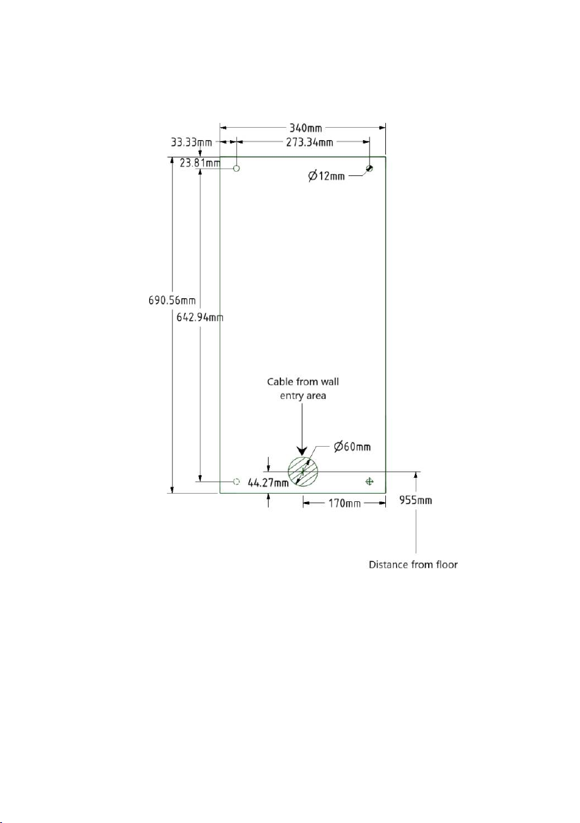
Must follow wall and floor clearance for maintenance and
operation work as Figure 1.1 and Figure 1.2.

E55 Plus Installation guide - Ver1.0
.
0
2
Figure 1.1 Wall recess from top view
Figure 1.2 Floor clearance

E55 Plus Installation guide - Ver1.0
.
0
3
●
Must have wall cabling with
:
●
Incoming local LAN network coverage (CAT5e or CAT6) with
minimum speed of 100Mbps.
●
Incoming AC power (240VAC 50/60Hz) from local sub-board
with supply isolators (e.g. MCBs or fuses)
●
An incoming analog intercom system connection if required.
●
Must define the cabling path:
●
On the wall. Must guide to the cable hole on top of E55 kiosk
(see Figure 1.3)
●
From the wall. Must guide the cable into cable hole area at
the back side of E55 Plus (See Figure 1.3 and 1.4).

E55 Plus Installation guide - Ver1.0
.
0
4
Figure 1.3 Cable entry into the E55 Plus Kiosk.

E55 Plus Installation guide - Ver1.0
.
0
5
Figure 1.4 E55 Plus wall base dimension

E55 Plus Installation guide - Ver1.0
.
0
6
Physical Installation
Tool list
In addition to the standard tools, the following tools are required to
setup the E55 Plus Kiosk
:
Hammer drill with stone drill XX,
Bolt wrench XX mm (for the body mounting)
Network cable tester
RJ45 Crimper
Hammer

E55 Plus Installation guide - Ver1.0
.
0
7
List of Enclosed Accessories
Here is the list of accessories together in the packaging:
Figure 2
.
1 Steel Masonry Anchor bolt set
1. 4 x Steel Masonry Anchor bolt set
(
XX mm drill hole / XX mm
deep
)
2. 1 x Wall mount template
3. 4 x Double sided tape
4. 2 x Set of key
On Wall Cabling
Cable entry for on wall cabling is covered with metal plate(See
Figure 1.3). By using hammer, knock the cover until it detach.
Install the Kiosk
Follow this procedure to install the E55 Plus Kiosk
:
1. Remove the packaging from the kiosk.
2. Look for the mini package containing manual, accessories and
key enclosed together with the terminal packaging.

E55 Plus Installation guide - Ver1.0
.
0
8
Figure 2.2: Mini package
3. Take wall mount template (Figure 2.3) and stick it by using
double sided tape on the wall
.
Make sure the side position of
kiosk, floor distance and cable hole area is correct.
4. Mark the location for drill holes based on the template. Remove
the mount template.
5.
C
reate the drill holes on wall and install the steel anchors. 4
fastening points is required. Remove the mount template.
6.
Lift the device into the fastening points on the wall.
7. Guide the power cable and the LAN cable to the cable entry
inside of the housing.
8. Fasten kiosk body to the wall with the washer
s
and nuts
provided.

E55 Plus Installation guide - Ver1.0
.
0
9
Figure 2.3: E55 Plus Wall mount template.

E55 Plus Installation guide - Ver1.0
.
0
10
Attaching AC Power
E55 Plus Kiosk require live wire, ground wire and earth wire from
incoming AC power. To attach incoming AC power:
1. Guide the AC power cable to the power connector.
Figure 2.4: Location of power connector, network switch and analog
intercom slave in E55 Plus Kiosk.

E55 Plus Installation guide - Ver1.0
.
0
11
2. Insert the power supply cable in accordance with the markings.
Attaching LAN Network
LAN network cable will be attached to the network switch inside the
kiosk. To attach LAN network:
1. Guide the LAN network cable to the network switch. Use the
cable conduit passage until reach the network switch (Figure 2.4)
.
2. Clamp the network cable head. Must use the 8P8C Way Male
Modular Plug Head.
3. Plug-in the network cable into available port at the network
switch.
Connect the intercom
Depending on the specification of the E55 Plus kiosk, intercom in the
E55 Plus kiosk can be either analogue type or digital type. For digital
intercom, no extra installation required. Please refer to the
seller/distributor for the product verification.
Analogue intercom connection
For analogue intercom system, E55 Plus will be equipped with slave
analog intercom. To connect the analog intercom:

E55 Plus Installation guide - Ver1.0
.
0
12
1. Guide the analog intercom cable from base to the slave intercom.
Use the cable conduit passage until reach the slave intercom (See
Figure 2.4)
.
2. Connect analogue intercom cable in accordance with the markings.
Figure 2.13: Slave analog intercom connection markings.

E55 Plus Installation guide - Ver1.0
.
0
13
Dimension

E55 Plus Installation guide - Ver1.0
.
0
14
Block Diagram
Figure 3.1: E55 Plus block diagram with analog intercom

E55 Plus Installation guide - Ver1.0
.
0
15
Figure 3.2: E55 Plus block diagram with digital intercom

E55 Plus Installation guide - Ver1.0
.
0
16
Technical data
Dimension 446 mm x 197 mm x 793
mm
Weight XX KG
Operating Voltage 220 - 240VAC / 50-60 Hz
Rated Current XX A
Ambient temperature 5°
C
– 65°
C
Protection Class IPXX
Card reader Mifare, Barcode, EMV,
TnGo
Display 24 Inch Full Color LCD
Warranty 1-year part warranty
Table of contents