WEISS FV802 User manual

Home Ventilation
System
Weiss (NZ) Limited
Installation and
Operation Manual
(FV802)
PRIOR TO INSTALLATION
Thank you for purchasing this quality Home Ventilation product by Weiss (NZ) Limited.
With your Weiss HVS™ correctly installed you can be assured of many years of trouble free operation.
PLEASE READ ALL INSTRUCTIONS CAREFULLY BEFORE COMMENCING INSTALLATION.
Note: Pictures and diagrams on packaging are designed only to be used as a concept. All installation details should be carried out as per the
instructions herein.
SAFETY NOTE
Electrical Note: Weiss (NZ) Limited recommends that the mains electrical installation be completed by a registered electrical contractor.
Please ensure the electrical installation of this product complies with local wiring regulations.
SYSTEM EFFICIENCY
The main points affecting system efficiency are:
•Internal doors should be left open to allow air flow
•No tight bends or kinks in the ducting to prevent flow restrictions
•Good air flow out of the home (existing externally ducted appliances will assist with this)
PLANNING YOUR INSTALLATION
Included with this system:
FV802
1 x main fan unit (with suspension chain)
2 x filter bags
3 x 3 metre lengths of insulated ducting
2 x outlet vents
1 x electronic control pad
1 x plug in connection cable for control pad (5 metres)
1 x wall mounting flush box
1 x 200mm junction
The first steps to installing your MAIN FAN UNIT are dependent on 3 main points:
•The placement of the outlet vents (Step 1)
•The layout of the insulated ducting (Step 3)
•The installation of the control pad connection cable (Step 7)
Step 1: PLACEMENT OF OUTLET VENTS
The outlet vents should be placed as far apart as the ducting will allow (i.e. 5 metres), with one situated in the main living area and the other in the
hallway by the bedrooms, or in the stairwell if the house is 2 stories. When placing outlets consideration should be given to obstacles (e.g. joists
etc) in the ceiling.
It is not necessary to put an outlet in the centre of a room.
Do not install outlet vents for this product into the Kitchen, Bathroom or other areas of high moisture content.
The outlet vents should be installed at least one metre away from smoke alarms or motion detection units.
The outlet vents need to be opened at least 25mm.
Step 2: INSTALLATION OF OUTLET VENTS
Use the cutting template on the bottom of the product packaging to mark out your ceiling for the outlet vent.
1) Use a saw to cut out the
pencil drawn lines. Before you
cut be sure to check above the
unit for a minimum clearance
space of 350mm, and the
location of the ceiling joists. The
fascia mounting back must fit
freely in the hole.
2) Unscrew the 3 retention
screws until the gap between the
toggles and the lip of the unit is
greater than the thickness of the
ceiling material. Fold toggles
inwards and insert the unit into
the hole.
3) Turn the retention screws
clockwise. This will turn the
toggles outwards. Tightening
the retention screws will allow
the toggles to grip the ceiling
material.
Fit the fascia ring on.
4) Finally, attach the ducting
tube to the rear and*, secure
with provided ducting tape,
repeat step for outlet vents.
Support ducting to prevent it
collapsing and restricting the
flow.
© Weiss (NZ) Limited 2005 Weiss (NZ) Limited reserves the right to alter designs and specifications without notice. R02:1110708
INSHVS

Step 3: LAYING OUT THE INSULATED DUCTING
Do not cut the insulated ducting, if it is too long try to mount the blower unit or outlet vents to accommodate the full length or spread the ducting out
in a large loop. Ensure there are no kinks, or tight bends – support (by suspending) if needed.
Step 4: INSTALLING THE MAIN FAN UNIT
Keep the main fan unit away from the bedroom area to keep any possible noise to a minimum.
The main blower unit is mounted by suspending it on the single chain provided.
Ensure the unit is not touching anything in the ceiling cavity as this may cause noise or vibration when the unit is running.
The main blower unit needs to be mounted as high as possible (check the control cable and ducting will reach prior to mounting) in the roof cavity,
as this will allow it to collect the warmest air in heat recovery mode.
Use the included 200mm wire securing ring in addition to the provided duct tape to ensure the permanent fitting of the ducting to the main blower
unit.
Step 5: FITTING OF FILTER BAGS (FV82)
The filter bags (FV82) are a tight fit and will need to be stretched over the bag holder ring; the Velcro tabs will hold the bags in place.
Step 6: MAINS SUPPLY TO FAN UNIT
A power outlet needs to be installed by a registered electrical contractor in the ceiling next to the fan unit, and the unit plugged in using the supplied
power cable and plug.
Any modifications to, or removal of this power cable will invalidate the warranty.
This unit contains sensitive electronic components that will be damaged by incorrect electrical installation.
Step 7: INSTALLATION OF CONTROL PAD
The included control pad and flush box should be installed by one of the outlet vents in the hallway (or stairwell) of your home.
Run the supplied 5metre control cable (with the push in connections on both ends) down the wall, this needs to be first plugged into the main unit,
and then into the control pad. DO NOT cut, shorten, modify, or use any other cable – surplus control cable should be left in the ceiling cavity.
*Modification of the control cable will invalidate the warranty.
There is no designated end to the control cable (i.e. either end can be plugged in at either connection).
ENSURE THE CONTROL PAD IS NOT IN DIRECT SUNLIGHT, OR NEAR A HEAT SOURCE SUCH AS A PANEL HEATER AS THE CONTROL
PAD CONTAINS A TEMPERATURE SENSOR.
Note: The control cable supplied to connect the unit to the control pad should be kept as far away from mains voltage cables, light cable, power
cables etc as possible and NOT coiled up.
Step 8 (Optional): DUCT TEMPERING UNIT
A separate Duct tempering unit (FH800) can be purchased to work in conjunction with your Weiss Home Ventilation System. The duct warming unit
is used to warm incoming air to your home on cool winter nights. This unit contains a 1,000-watt element and is controlled electronically from your
Home Ventilation System; the heater temperature is based on your ceiling cavity temperature, and the program setting you have selected
(see section 4).
Step 9 (Optional): INSTALLATION OF DUCT TEMPERING UNIT (FH800 – Optional Extra)
To install a duct tempering unit, the power must be completely disconnected from the entire Weiss Home Ventilation system, The Duct tempering
unit needs to be fitted as close as possible to the main blower unit (less than 300mm).
PROGRAMMING AND CONTROL
FIRST POWER UP OF THE SYSTEM
Connect the main power and control cable. The order of these connections is not important. The ventilation system will automatically start when all
connections are completed. It will then take 20 seconds for the system to start, following this the On / Off LED will blink for approximately 2 minutes
as the system initialises.
When initialising is complete the auto/manual LED will illuminate, the program LED will illuminate and the bottom Speed button will illuminate. The
system will now be running in auto program 1.
The system will then continue to run in automatic mode in the default program (System Setting 1).
If this setting does not suit your house size, i.e. less than 100m2ensure the system is in automatic mode (indicated by the Manual / Auto LED being
on) and then use the ‘speed’ up / down buttons to select another program that suits your home size, from the program chart. Make sure the LED
light pattern matches the setting you require.
The settings can be changed rapidly at any time and become the default setting 1 hour after the change has been made.
Always leave the unit turned on. If your house is over approximately 22 degrees the system will go to Standby mode and wait until the temperature
drops, when it will restart again.
For Systems fitted with a duct tempering unit
The winter button turns the duct warmer on and off and will illuminate when pressed but will not turn the warmer on until the temperature in the
ceiling drops below 13.
The duct tempering unit is always controlled by a microprocessor located in the main unit and the programme you have selected
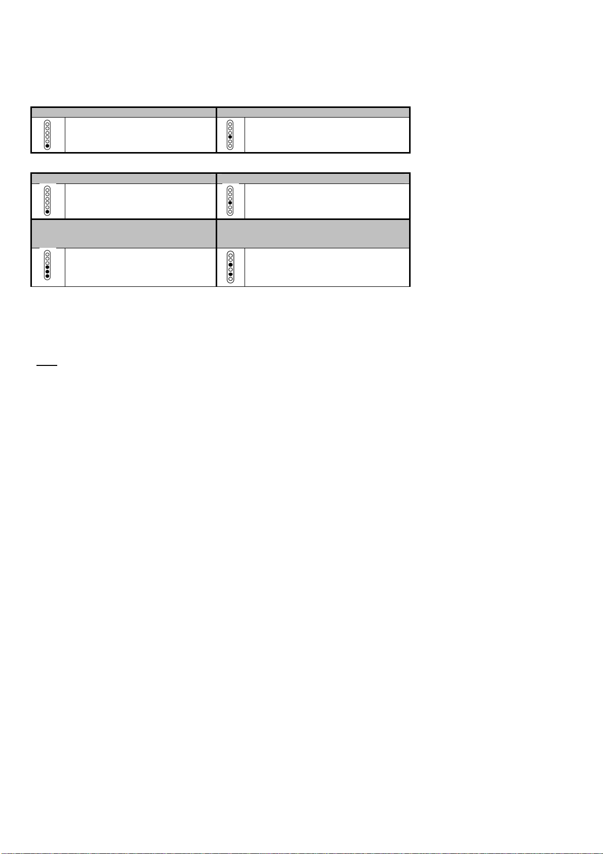
RECOMMENDED SETTINGS
FOR FV802 – Dual Outlet Home Ventilation System ONLY – (Without a Duct Tempering Unit):
© Weiss (NZ) Limited 2005 Weiss (NZ) Limited reserves the right to alter designs and specifications without notice. R02:1110708
INSHVS

If a duct tempering unit is not fitted, select SYSTEM SETTING 1 for a small home, and SYSTEM SETTING 4 for a medium home, SYSTEM
SETTING 7 for a large home, and SYSTEM SETTING 10 for an extra large home (see Table 2 for the correct light pattern).
If a duct warming unit is fitted, refer to the separate included instructions for the program settings that relate to that unit.
These tables show the light patterns that need to be displayed on the ‘Speed’ LED’s for the various home sizes:
TABLE 1
SETTING FOR A HOME UNDER 100m2SETTING FOR A HOME UNDER 160 m2
System Setting 1 System Setting 4
For a Small House (Less than 100m2) For a Medium House (Less than 160 m2)
TABLE 2 - FV802 ONLY
SETTING FOR A HOME UNDER 100m2SETTING FOR A HOME UNDER 160 m2
System Setting 1 System Setting 4
For a Small House (Less than 100m2) For a Medium House (Less than 160 m2)
SETTING FOR A HOME UNDER
250 m2
SETTING FOR A HOME OVER 250m2– It is
recommended that 2 units are fitted in this
situation.
System Setting 7 System Setting 10
For a Large House (Less than 250 m2) For a Large House (Greater than 250 m2)
CONTROLLING THE UNIT
AUTO / MANUAL BUTTON
Manual Mode: - The ‘Auto / Manual’ Button switches between these two functions.
In manual mode you can select any of 6 possible fan speeds by pressing the ‘Speed Up / Down’ button. The unit will continue to run at this speed
until another speed is selected.
Note: In manual mode – no programs are selected, and the speeds are not controlled by temperature. The ‘Winter’ mode (Duct tempering unit) is
not available in manual mode.
Auto mode is selected by pressing the ‘Auto / Manual’ Button. Auto mode is on when the LED is illuminated. The ‘Up / Down’ buttons can now be
used to move through the 12 main programs. Make sure the LED light pattern matches the setting you require.
The program selected will automatically become the default program if the program settings are not changed for 1 hour.
ON / OFF BUTTON
This button turns the system On or Off
PROGRAM BUTTON
This function is only accessible by a qualified technician.
WINTER BUTTON
The winter button will manually switch the duct tempering unit (FH800) On / Off, if an optional duct tempering unit has been fitted to your system.
With the Winter button set to On, the duct tempering unit is controlled by a microprocessor located in the main unit. This button will operate if a
duct tempering unit is not fitted.
RESET WARNING
If all the indicator lamps on the control pad are flashing, this indicates a control fault, the control cable will need to be checked to ensure it is not
damaged or disconnected.
KEY LOCK FUNCTION
The control pad is programmed with a key lock. Pressing and holding the ‘On/Off’ key followed immediately by the ‘Manual/Auto’ key and held for 2
seconds will activate this. The key lock is turned off using the same procedure. (Function entry is indicated when all lights on the touch pad flash
once).
FILTER INDICATOR
This LED will illuminate after approximately 12 months of operation, indicating the air filter bags need to be replaced.
After the bags are replaced, the indicator lamp can be reset by pressing ‘On / Off’ key followed immediately by the ‘Winter’ key and holding for 2
seconds. (Function entry is indicated when all lights on the touch pad flash once).
STATUS INDICATOR
This function is only accessible by a qualified technician.
POWER CUTS
If there is a power cut / mains power failure the unit will automatically re-start in the program to which it was last set. Providing the program was
entered at least 1 hour before the power cut.
TROUBLESHOOTING THE SYSTEM
What do I do if the Weiss HVS stops working?
If your unit stops working for a period of longer than 24 hours, please contact your local Weiss product supplier.
What is wrong with my unit – the lights are all on, but the keypad does not respond?
You may have put the system into Key-Lock mode, which can be turned off by pressing and holding the ‘On/Off’ key followed immediately by the
‘Manual/Auto’ key and held for 2 seconds.
© Weiss (NZ) Limited 2005 Weiss (NZ) Limited reserves the right to alter designs and specifications without notice. R02:1110708
INSHVS

An area of my home is still fairly damp even though I have the internal doors open – why is this?
You will need to ensure that there is someway for the air to escape to the outside of the home close to the effected location.
The normal operation lights on the control pad are on, but the fan does not seem to be operating?
If your home is over 22 degrees Celsius, the fan unit will be in stand by mode waiting for the temperature of the home to drop below 22 degrees
before the unit will restart.
FREQUENTLY ASKED QUESTIONS
What maintenance is required?
The only maintenance requirement for the Weiss HVS is the changing of the filter bags. The microprocessor touch pad will illuminate the change
filter light at the end of a twelve-month period.
How long will it take before I know whether or not the Weiss HVS unit is working?
Most homeowners notice a dramatic reduction in condensation and mould build up within a period of two-four weeks
Do I need to switch the Weiss HVS off in summer?
It is recommended that the Weiss HVS is left on continuously, as the unit is fitted with dual microprocessors that sense temperature in the roof
cavity and the home, and adjusts itself accordingly, to suit both summer and winter climates.
Can the Weiss HVS be used as a Heat Transfer System?
No, the unit is not designed to transfer heat between rooms.
Can the home handyman install the unit?
Yes. The home handyman can install the unit, however, it is recommended that a registered Electrician complete the mains wiring.
Can a duct tempering unit be fitted to this unit after installation?
Yes. The microprocessor automatically senses a tempering unit installation and controls the unit accordingly.
Will the Weiss HVS System work the same with the internal doors in my house closed?
No, air circulation throughout the house is required for maximum efficiency, so internal doors should be left open.
Do I need an outlet vent downstairs in a two-storied house?
Yes, this would be ideal, but as most installations are into existing homes, this is generally not possible. Your system will still work with the outlet
vents upstairs but it may be necessary to allow some air to escape from the downstairs area to the outside.
SUITABILITY
•Weiss HVS™ has been designed to fit into your roof space/ceiling cavity.
•This unit is NOT designed to be installed outside of your home.
•Weiss HVS™ must not be mounted in areas subject to direct splashing.
•Refer to New Zealand standard NZECP2: 1988 Section 4.6 and Australian Standard AS3000:1991, Section 6.2.
ROOF SPACE MOISTURE
The roof cavity needs to be checked to ensure there are no leaks, or moisture being directly vented into the cavity from un-ducted kitchen /
bathroom extraction, or uncovered water tanks.
MOISTURE IN THE HOME
The following items also need to be taken into consideration when installing the system:
•Un-flued gas heaters generate substantial amounts of moisture and will reduce the effectiveness of the system (HVS should not be used in
conjunction with these types of units).
•There needs to be adequate general heating in the home – Health Department recommendation is a minimum internal temperature of 15oC in
winter.
•Moisture/steam should be extracted from the bathroom(s), laundries and un-vented clothes dryers, and expelled outside (not into the ceiling).
•For optimum performance of the unit, the walls/ceilings of the home need to be adequately insulated.
•The drying of clothes by fires / or heaters in the home expels a large amount of moisture and can effect the overall performance of the unit.
GENERAL REQUIREMENTS
•Check that there is adequate ventilation into the roof cavity; this is to enable the system to draw from the dryer air outside of the home.
•Unenclosed down lights may affect the performance of this unit (air will not be drawn from the outside of the home, but instead the damp air
inside the home will be re-circulated).
•High studs, badly insulated or cold homes will remain more difficult to keep dry than low ceiling – well insulated warm homes.
•The supply cord of this equipment cannot be replaced. If it is damaged the entire unit should be replaced.
•Precautions must be taken to avoid the back flow of gases into the room from the open flue of gas or other open fire appliances.
•These systems are only designed for use with the one or two outlets supplied in the kit.
© Weiss (NZ) Limited 2005 Weiss (NZ) Limited reserves the right to alter designs and specifications without notice. R02:1110708
INSHVS
Other WEISS Fan manuals