Wellav smp100 User manual

Simple Media Platform Quick Installation Guide V1.0-N
Simple Media Platform
Quick Installation Guide

2
Simple Media Platform Quick Installation Guide V1.0-N
1.InstallationInstruction
1.1 Mounting unit to a 19” rack
When selecting the installation site, try to comply with the following:
zProtective Ground - The protective ground lead of the building's electrical
installation should comply with national and local requirements.
zEnvironmental Condition - The installation site should be dry, clean, and
ventilated. Do not use this equipment where it could be at risk of contact with water.
To avoid electric shock, make sure the rack has been correctly grounded
before switching on the device.
To mount the unit to a 19”/42U rack, please perform the following steps:
1. Make sure the mounted rack surface is stable and can support the size and weight of this
equipment.
2. For single unit mounting, use an “L” shape slide (not included in the package) to support
holding the unit if necessary, and fastened with appropriate screws to each side of the
chassis’ rails.
L-shape slide
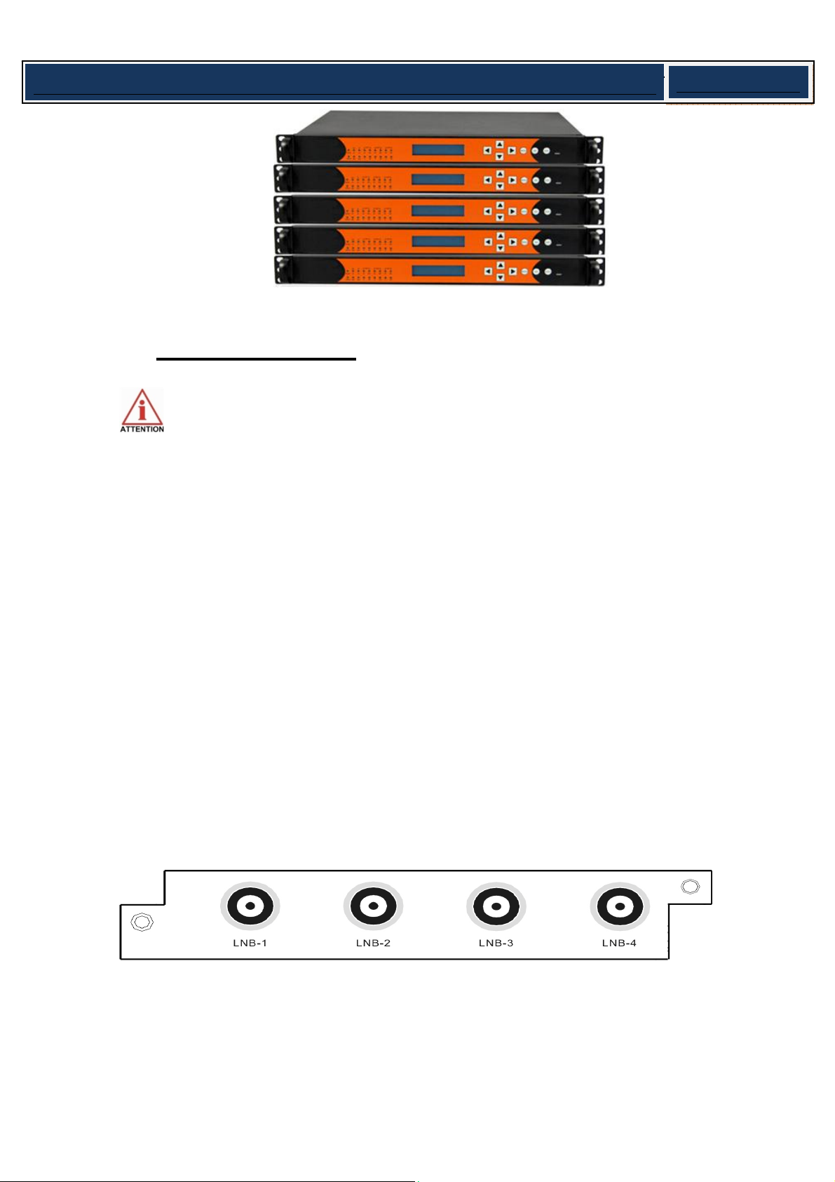
3. For group pile up (no space between each unit), the unit should be placed on a flat
holding bracket. No more than 5 units for each group, and leave at least one unit space
between each group to ensure good air ventilation.
3
Simple Media Platform Quick Installation Guide V1.0-N
5.2 Wiring Connection
Before setting up the connection, please turn off the equipment and all other
connected external devices. The equipment and all connected external devices are
required grounded. Turn on the devices only after the wiring connection is completed.
Otherwise the device may be damaged.
There are three slots on the real panel of the unit. Each slot supports all types of the
modules which are developed for the platform.
After you have inserted all the modules to the unit, start to connect the DMP according to its
inserted modules and set up per the application requirement.
1. DVB-S/S2 module: there are four RF ports on the module, each can be connected to one
transponder to receive a TS delivered from it. You can use four RF cables to connect the RF
ports to the antenna.
2. DVB-C module: there are four RF ports on the module, within them, port 2 & 4 (marked
with RF-IN 1/2 and RF-IN 3/4) are signal input ports, and port 1 & 3 are loop out ports. You

4
Simple Media Platform Quick Installation Guide V1.0-N
can use two RF cable to connect the module with cable source at the two signal input ports.
And if necessary, you can loop out the signal for other usage.
3. DVB-T/ISDB-T module: The DVB-T / ISDB-T module supports receiving programs
compliant with DVB-T / ISDB-T standard from 4 different frequencies simultaneously. Similar
to DVB-S/S2, four ports on the module. Four cables can be used to connect the four RF
ports with the signal source.
4. ASI Module: The ASI module is equipped with four BNC-type ASI connectors, supporting
four ASI inputs/outputs. The default setting of the module is: Ports 1 & 2 is for input, and
Ports 3 & 4 is for output. User can specify the port to be input or output at any time through
the NMS. According to your application, connect the four ports to the corresponding devices
(receive or send) with ASI cable.
5. GbE IP I/O Module The IP module is equipped with two RJ45 connectors and two SFP
connectors. These two types of connectors can not be used simultaneously. For both the
RJ45 connectors or SFP connectors: the left one is for the IP stream input/output; The other
is for stream output only, and it is as the backup output when you set the left port as output
mode.
Connect the TS/IP port with the IP stream receiving or sending devices according to your
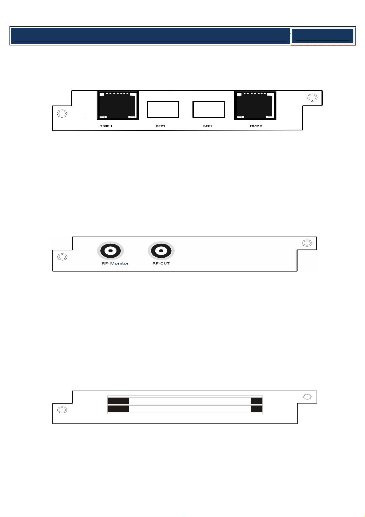
5
Simple Media Platform Quick Installation Guide V1.0-N
application. If you need to use the IP board for both receiving and transmitting data, you can
connect the left port to a signal source, and the right to a IP stream receiving device.
6.QAM/COFDM Module: The QAM/COFDM module can output up to 8 separate RF QAM
frequencies signals with one physical output interface, and extra monitor port is used for
local monitoring. With adopting corresponding license key, the module can turn to be a
4-COFDM module without changing the hardware. Connect the module with a RF cable
to the HFC.
7. CI Descrambling Module: The CI descrambling module is for decoding TV programs
scrambled with conditional access system. The module supports 2 CAMs working
simultaneously. Insert appropriate CAM card with smart card to decode program.
Note: different CAM card support different conditional access system. Before you
insert the card, you need to figure out by what kind of the CAS the program is
scrambled, you can inquire the information from the content provider.
8. 2 SD&HD H.264 SDI/AV Encoder Module: The 2-SD&HD H.264 SDI/AV Encoder
Module supports encoding 2 SDI channels or 2 AV channels simultaneously. To encode a

6
Simple Media Platform Quick Installation Guide V1.0-N
program from AV source, a specified AV cable, which is packed in your package, is
needed to connect the source to the CVBS/SDI port and the L-Audio-R port next to it. To
encode a program from SDI source, one common SDI cable is needed to connected the
source to the CVBS/SDI interface.
9. SD MPEG2 SDI/AV Encoder Module: The 2 SD MPEG2 SDI/AV Encoder Module
supports encoding 2 SDI channels or 2 AV channels simultaneously. To encode a
program from AV source, a specified AV cable, which is packed in your package, is
needed to connect the source to the CVBS/SDI port and the L-Audio-R port next to it. To
encode a program from SDI source, one common SDI cable is needed to connected the
source to the CVBS/SDI interface.
10. SD MPEG2 AV Encoder Module: The 2-SD MPEG2 AV Encoder Module supports
encoding 2 AV channels simultaneously. To encode a program from AV source, a
specified AV cable, which is packed in your package, is needed to connect the source to
the CVBS/SDI port and the L-Audio-R port next to it.
11. HD H.264 HDMI Encoder Module: The HD H.264 HDMI Encoder Module supports

7
Simple Media Platform Quick Installation Guide V1.0-N
encoding 2 HDMI channels simultaneously. You can use a HDMI cable to connect the
HDMI source to the HDMI port of the module.
12. DVB Scrambler Module: Connect the RJ45 port with crossover Ethernet cable to the
CAS server. (You may need a switch to setup the connection.)
13. MPEG2toMPEG4Transcoder/MPEG4toMPEG2TranscoderModule:Physicalconnectionis
notnecessaryforthismodule.
14. Power: There are two swappable power supply units (one for redundant), you can
connect them with two different power supply sources.
Connect this equipment only to the power sources that are identified on the
equipment-rating label normally located close to the power inlet connector(s).
Always pull on the plug or the connector to disconnect a cable. Never pull on the
cable itself.
To protect your valuable interests and services, equipping a UPS
(Uninterrupted Power Supply) and an AVR (Automated Voltage Regulator) to the
8
Simple Media Platform Quick Installation Guide V1.0-N
system is highly recommended.
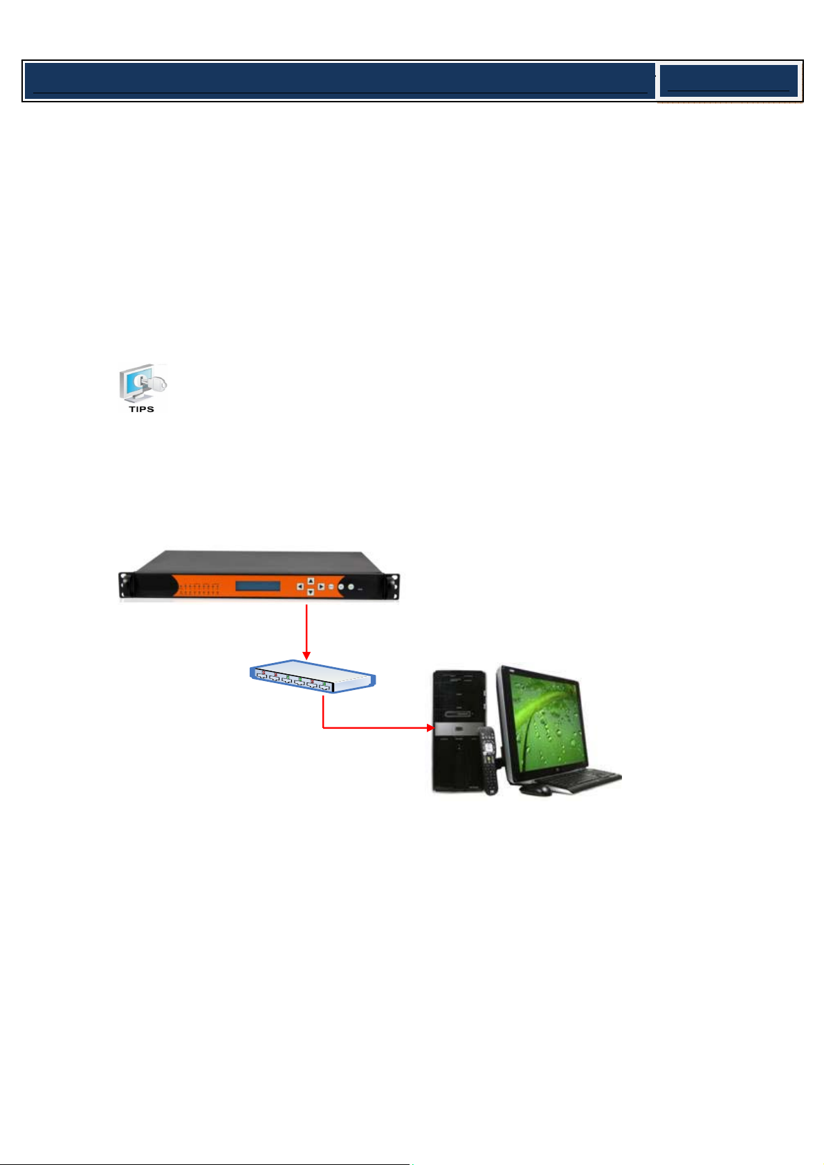
15. Management Port Connection: Connect the Management Port on the rear Panel to a
switch, and then connect the switch to a Monitor computer with crossover Ethernet
Cable. (PIC-5.2-2)
Note: The equipment can be connected directly to a monitor PC using a crossover
Ethernet cable.
In order to ensure a smooth communication between the management PC and
the equipment, please separate the connection of management port and TS/IP output
port to different switch. The switch with management port connected should be
without large data processing.
16.Ground Protective: Connect the Ground Port to the Rack with a lead wire.
PIC-5.2-2
Switch

9
Simple Media Platform Quick Installation Guide V1.0-N
6.OperationInstructions
6.1 Powering Up & Initializations
Before powering-up the device, make sure that all cabling is correctly
connected. The device is correctly connected to the power inlet and grounded.
When you have finished the wiring, power up the device, you can see the booting
information through the LCD screen on the front panel, the initialization will take about one
or two minutes.
After the initialization is finished, the Device Name and its IP address will appear on the LCD
screen (PIC-6.1-1).
If the unit fails to initialize and hangs at the “booting” stage, swtiching off the
device and then powering up again may help. If the device still fails to initialize,
please contact your service representative for help.
6.2 Enter the NMS interface
This unit provides a user-friendly UI interface for you to easily configure the device and
constantly monitor the device status. Before you can configure the unit through the NMS,
you need to set up a stable connection between the device and the monitor server. Below
steps will help:
Device Name
IP : 192. 168. 001. 016
PIC-6.1-1

10
Simple Media Platform Quick Installation Guide V1.0-N
1. Setup a connection between the media platform and monitor PC.
Note: Step 1 to Step 2 is operated from the front panel. There are six buttons on
the front panel: Up / Down / Left / Right / Menu / OK / Esc for you to manually
configure the basic parameters of the device.
zStep 1: Check out the device IP
Press MENU button to enter main menu.
Press UP button and DOWN to navigate to the sub menu System.
Press OK to Enter the Sub menu Ethernet Setup, within it, press UP button and DOWN
button, you can check out the IP, Gateway, Subnet Mask, etc.
zStep 2: Change the IP, Gateway and Subnet Mask to make it in the same network
section as the management PC:
Example:
Media Platform Management PC
IP Address 192.168.1.16 192.168.1.28
Gateway 192.168.1.1 192.168.1.1
Sub Mask 255.255.255.0 255.255.255.0
Note: to Change a parameter, you can first press OK button, Then the parameter
will be selected with a blinking short line under its first character (or number),
then you can use UP and DOWN button to change the parameter’s value as you
desired, press OK button to take effect.
zStep 3: After you have setup the above parameters, press MENU button to exit the
configuration, the device will reboot automatically.
zStep 4: Ping the new IP of the device through the management PC to check the
connectivity.
2. Enter the NMS interface
Step 1: Start the Network Management Software on the accessory CD in you package.
Network Management Software Icon
Other manuals for smp100
1
Table of contents
Other Wellav Server manuals


