Weq CFW700 Series Instructions for use

Motors | Automation | Energy | Transmission & Distribution | Coatings
SOLAR PUMP DRIVE
CFW700
Application Manual
Language: English
Document: 10006763201/ 04

Application Manual
Solar Pump Drive
Series: CFW700
Language: English
Document Number: 10006763201 / 04
Publication Date: 12/2022

Contents
Solar Pump Drive | 3
CONTENTS
ABOUT THE MANUAL ..............................................................................4
ABBREVIATIONS AND DEFINITIONS..................................................................................................... 4
NUMERICAL REPRESENTATION........................................................................................................... 4
QUICK PARAMETER REFERENCE..........................................................5
FAULTS AND ALARMS.............................................................................7
1 SAFETY INSTRUCTIONS.......................................................................8
1.1 SAFETY WARNINGS IN THIS MANUAL............................................................................................ 8
1.2 SAFETY WARNINGS IN THIS PRODUCT ......................................................................................... 8
1.3 PRELIMINARY RECOMMENDATIONS............................................................................................. 8
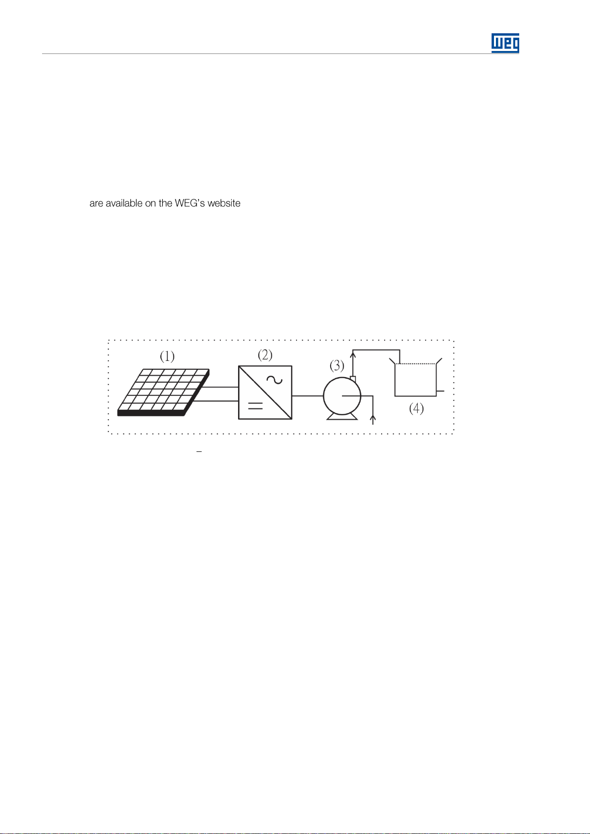
2 PHOTOVOLTAIC WATER PUMPING SYSTEM...................................10
2.1 OVERVIEW OF THE CFW700 IN PHOTOVOLTAIC SYSTEMS ....................................................... 10
2.2 GENERAL CHARACTERISTICS OF THE SOLAR PUMP................................................................ 10
3 INSTALLATION ....................................................................................12
3.1 SIZING OF PHOTOVOLTAICS SOLAR MODULES......................................................................... 12
3.2 CONNECTIONS............................................................................................................................... 15
3.2.1 T4 Model................................................................................................................................... 15
3.2.2 T4 Model with Hybrid Power.................................................................................................... 16
4 CONTROL METHOD BY MAXIMUM POWER POINT TRACKING .....17
5 PARAMETERS DESCRIPTION ............................................................18
5.1 VOLTAGE REGULATOR.................................................................................................................. 18
5.1.1 Voltage Setpoint Limits............................................................................................................ 18
5.1.2 Voltage PID Controller ............................................................................................................. 19
5.1.3 Cloud/Load Controller ............................................................................................................. 19
5.1.4 System Start Configuration ..................................................................................................... 20
5.1.5 Solar Detector.......................................................................................................................... 21
5.2 PRESSURE CONTROLLER............................................................................................................. 23
5.2.1 Pressure PID Controller........................................................................................................... 24
5.2.2 Sleep Mode............................................................................................................................... 25
5.3 PROTECTIONS................................................................................................................................ 25
5.3.1 Dry Pump.................................................................................................................................. 26
5.3.2 Minimum Output Pressure....................................................................................................... 27
5.3.3 Maximum Output Pressure...................................................................................................... 27
5.4 CONTROL SETPOINT..................................................................................................................... 28
5.5 HMI MONITORING.......................................................................................................................... 29
5.6 READING PARAMETERS................................................................................................................ 29
6 POWER UP AND START UP................................................................31

About the Manual
Solar Pump Drive | 4
ABOUT THE MANUAL
This manual provides the necessary information for the configuration of Solar Pump Drive application developed
with the CFW700 inverter SoftPLC function. This application manual must be used together with the CFW700
ABBREVIATIONS AND DEFINITIONS
PLC Programmable Logic Controller
CRC Cycling Redundancy Check
RAM Random Access Memory
USB Universal Serial Bus
WLP Ladder Language Programming Software
NUMERICAL REPRESENTATION
Decimal numbers are represented by means of digits without suffix. Hexadecimal numbers are represented with
the letter 'h' after the number.

Quick Parameter Reference, Faults and Alarms
Solar Pump Drive | 5
QUICK PARAMETER REFERENCE
Parameter
Description
Adjustable Range
Application Default
60 Hz (50 Hz)
User
Setting
Prop.
Groups
Page
P0100
Acceleration Time
0.1 to 999.0 s
20.0 s
BASIC
-
P0101
Deceleration Time
0.1 to 999.0 s
20.0 s
BASIC
-
P0133
Minimum Speed
0 to 18000 rpm
2400 (2000) rpm
BASIC
-
P0134
Maximum Speed
0 to 18000 rpm
3600 (3000) rpm
BASIC
-
P0136
Manual Torque Boost
0.0 to 30.0 %
According to
inverter model
V/F
MOTOR,
BASIC
-
P0142
Maximum Output Voltage
0.0 to 100.0 %
100.0 %
cfg V/F
-
P0143
Intermediate Output Voltage
0.0 to 100.0 %
60.0 %
cfg V/F
-
P0144
Minimum Output Voltage
0.0 to 100.0 %
28.0 %
cfg V/F
-
P0202
Control Type
0 to 5
0 (1) = V/F
cfg
STARTUP
-
P0205
Main Display Parameter
2 = Speed in rpm
5 = Frequency in Hz
5 = Output Freq.
HMI
29
P0206
Secondary Display Parameter
0 to 1500
4 = DC Link Voltage
HMI
29
P0207
Parameter for Bar
0 to 1500
3 = Motor Current
HMI
29
P0208
Ref. Eng. Scale Main Display
0 to 65535
600
HMI
29
P0209
Main Display Eng. Unit
3 = rpm
13 = Hz
13 = Hz
HMI
29
P0210
Main Display Decimal Place
0 to 7
1 = wxy.z
HMI
29
P0220
LOC/REM Selection Source
0 to 11
1 = Always Remote
cfg
I/O
-
P0222
REM Reference Sel.
0 to 17
7 = SoftPLC
cfg
I/O
-
P0226
REM Rotation Selection
0 to 12
0 = Clockwise
cfg
I/O
-
P0227
REM Run/Stop Selection
0 to 5
1 = DIx
cfg
I/O
-
P0228
REM JOG Selection
0 to 6
0 = Disable
cfg
I/O
-
P0230
Dead Zone (AIs)
0 to 1
1 = Active
cfg
I/O
-
P0231
AI1 Signal Function
5 = Pressure PID
Feedback
3 = Not Used
I/O
23
P0233
AI1 Input Signal
0 = 0 to 10 V
1 = 4 to 20 mA
0 = 0 to 10 V
I/O
-
P0235
AI1 Input Filter
0.00 to 16,00
0,30 s
I/O
-
P0236
AI2 Signal Function
6 = Solar Sensor
Detector
7 = Control Setpoint
3 = Not Used
cfg
I/O
22
P0238
AI2 Input Signal
0 to 3
0 = 0 to 10 V
cfg
I/O
-
P0251
AO1 Signal Function
11 = Repeat AI1
2 = Real Speed
cfg
I/O
23
P0263
DI1 Input Function
0 to 31
1 = Run / Stop
cfg
I/O
-
P0264
DI2 Input Function
25 = Pressure PID
Man/Auto
27 = Power by Group
or Network
27 = Power by Group or
Network
cfg
I/O
23/
43
P0265
DI3 Input Function
26 = 1st DI for Control
Setpoint Selection
27 = Power by Group
or Network
26 = 1st DI for Control
Setpoint Selection
cfg
I/O
23/
29
P0266
DI4 Input Function
26 = 2nd DI for Control
Setpoint Selection
27 = Power by Group
or Network
26 = 2nd DI for Control
Setpoint Selection
cfg
I/O
23/
29
P0275
DO1 Output Function
34 = Triggers External
Power
11 = Run
I/O
23
P0276
DO2 Output Function
2 = N > Nx
I/O
23
P0277
DO3 Output Function
1 = N* > Nx
I/O
23
P0296
Inverter Rated Voltage
0 to 7
According to
inverter model
cfg
-
P0320
FlyStart/Ride-Through
0 to 3
3 = Ride-Through
cfg
-
P0331
Voltage Ramp
0.2 to 60.0 s
10.0 s
V/f
-
P0339
Output Voltage Compensation
0 to 1
1 = Active
cfg V/f
-
P0340
Auto-Reset Time
0 to 255 s
255 s
26
P0400
Motor Rated Voltage
200 to 600 V
According to
inverter model
cfg
MOTOR,
STARTUP
-
P0401
Motor Rated Current
0.0 to 200.0 A
According to
inverter model
cfg
MOTOR,
STARTUP
-
P0402
Motor Rated Speed
0 to 30000 rpm
According to
inverter model
cfg
MOTOR,
STARTUP
-
P0403
Motor Rated Frequency
0 to 500.0 Hz
60.0 (50.0) Hz
cfg
MOTOR,
STARTUP
-

Quick Parameter Reference, Faults and Alarms
Solar Pump Drive | 6
Parameter
Description
Adjustable Range
Application Default
60 Hz (50 Hz)
User
Setting
Prop.
Groups
Page
P1001
Command for SoftPLC
0 to 2
1 = Run Program
SPLC
-
P1010
Solar Pump Drive Application
Version
0.00 to 10.00
-
ro
SPLC
29
P1011
Current Tracking Setpoint
0 to 1000 V
-
ro
SPLC
29
P1012
Actual Pressure Setpoint / Speed
0.0 to 4000.0 [Eng. Un.1]
-
ro
SPLC
29
P1013
Pressure Reading
0.0 to 300.0
-
ro
SPLC
29
P1014
Running Time
0 to 65535 h
-
ro
SPLC
30
P1015
Total Energy
0 to 65535 kWh
-
ro
SPLC
30
P1016
Remaining Time to a new Start
Attempt
0 to 3600 s
-
ro
SPLC
30
P1017
Deviation Stopping Value of AI2
0.0 to 100.0 %
0.0 %
SPLC
22
P1019
Increment Rate MPPT
10 to 40
20
SPLC
18
P1022
Minimum Setpoint Vdc
0 to 1000 V
440 V
SPLC
18
P1023
Maximum Setpoint Vdc
0 to 1000 V
750 V
SPLC
18
P1024
PID Proportional Gain Vdc
0.000 to 32.000
1.000
SPLC
19
P1025
PID Integral Gain Vdc
0.00 to 32.00
20.00
SPLC
19
P1026
PID Integral Gain Vdc
0.000 to 32.000
0.00
SPLC
19
P1027
Time Between Starts
0 to 3600 s
60 s
SPLC
21
P1028
Enable Starting Value of AI2
0.0 to 100.0 %
0.0 %
SPLC
21
P1029
Actuation Value DOx
AI2 Value to Start an External Power
Source (Network / Group)
0.0 to 100.0 %
0.0 %
SPLC
22
P1030
Pressure Control
0 = Manual
1 = Automatic
2 = DIx Selection
3 = Disabled
3 = Disable
SPLC
23
P1031
Pressure Sensor Scale
0.0 to 300.0
10.0
SPLC
24
P1032
PID Proportional Gain Pressure
0.000 to 32.000
1.000
SPLC
23
P1033
PID Integral Gain Pressure
0.00 to 320.00
10.00
SPLC
24
P1034
PID Integral Gain Pressure
0.000 to 32.000
0.000
SPLC
24
P1035
Motor Speed below which Solar
Pump Drive goes to Sleep Mode
0 to 4000 [P0209]
0 [P0209]
SPLC
25
P1036
Time Delay for Solar Pump Drive
goes to Sleep Mode
1 to 65000 s
10 s
SPLC
25
P1037
Control Process Variable Deviation
for Solar Pump Drive to Wake Up
0.0 to 300.0
0.0
SPLC
25
P1038
Cloud/Load Controller Activation
Level
0.0 a 100.0 %
1.0 %
SPLC
20
P1039
Cloud/Load Controller Gain
0.00 a 10.00
1.00
SPLC
20
P1040
Time Delay for Dry Pump Fault
(F765)
0 to 65000 s
0 s
SPLC
26
P1041
Motor Speed for Dry Pump
0.0 to 4000.0 [P0209]
54.0 (45.0) [P0209]
SPLC
26
P1042
Motor Current for Dry Pump
0.1 to 100.0 %
45.0 %
SPLC
23
P1043
Time Reset Fault for Dry Pump
0 to 6500 min
0 min
SPLC
26
P1044
Minimum Output Pressure
0.0 to 300.0
0.0
SPLC
26
P1045
Minimum Fault Pressure Time
0 to 65000 s
0 s
SPLC
27
P1046
Maximum Output Pressure
0.0 to 300.0
10.0
SPLC
27
P1047
Maximum Fault Pressure Time
0 to 65000 s
0 s
SPLC
27
P1049
Actuation Time DOx
0 to 65000 s
0 s
SPLC
22
P1051
Control Setpoint 1
0.0 to 4000.0 [Eng. Un.1]
60.0 (50.0)
SPLC
28
P1052
Control Setpoint 2
0.0 to 4000.0 [Eng. Un.1]
1.5
SPLC
28
P1053
Control Setpoint 3
0.0 to 4000.0 [Eng. Un.1]
1.5
SPLC
28
P1054
Control Setpoint 4
0.0 to 4000.0 [Eng. Un.1]
1.5
SPLC
28
P1059
Running time ((P1014) and Total
Energy kWh (P1015) Reset
0 = Not Used
1 = Reset Running Time
2 = Reset Total Energy
0 = Not Used
SPLC
28
2

Quick Parameter Reference, Faults and Alarms
Solar Pump Drive | 7
FAULTS AND ALARMS
Fault / Alarm
Description
Possible Causes
F021:
Undervoltage on the DC Link
Undervoltage fault on the intermediate circuit.
The input voltage is too low and the DC link
voltage dropped below the minimum permitted
value (monitor the P0004 parameter value):
Ud < 223V - 200 / 240V three-phase input voltage
(P0296=0);
Ud < 170V - 200 / 240V single-phase input
voltage (P0296=0);
Ud < 385V - 380 V input voltage (P0296 = 1);
Ud < 405V - 400 / 415V input voltage (P0296=2);
Ud < 446V - 440 / 460V input voltage (P0296= 3);
Ud < 487V - 480V input voltage (P0296=4);
Ud < 530V - input voltage 500 / 525V (P0296=5);
Ud < 580V - input voltage 550 / 575V (P0296=6);
Ud < 605V - input voltage 600V (P0296=7);
Phase loss at the inverter input;
Pre-charge circuit failure;
Parameter P0296 was set to a value higher than
the power supply rated voltage.
A163:
Signal Fault AIx 4..20 mA
Analog input signal AIx at 4 to 20 mA or 20 to 4 mA
is below 2 mA.
Current signal on the analog input AIx interrupted
or null.
Error in the parameterization of analog input Aix.
A750:
Sleep Mode Active
It indicates that the Solar Pump Drive is in the sleep
mode.
Value of the pump motor speed is below the
threshold programmed in P1035 during the time
programmed in P1036.
A752:
Starting Time
It indicates that the time between start attempts has
started, the remaining time to the new start attempt
can be followed in P1016.
Starting Time was due to lack of Solar Drive
power (low power on solar panels)
A754:
DC Checking Routine
It indicates that the drive is trying to accelerate to
minimum speed and checking the DC bus behavior.
DC Bus checking alarm occurs at each start
attempt when there is no measurement of a Solar
Detection Sensor (AI2).
A756:
Low Level Solar Detection
It indicates that there is Low Solar radiation (AI2).
The system is attempting to start with a low-level
measurement of a Solar Detection Sensor (AI2).
F761:
Minimum Pressure
Minimum system pressure failure.
The system pressure is below the value of P1044
for the time programmed in P1045.
F763:
Maximum Pressure
Maximum system pressure failure.
The system pressure is above the value of P1046
for the time programmed in P1047.
F765:
Dry Pump
It indicates that the pump was stopped due to dry
pump protection.
During a time (P1040) the value of the pump
motor speed remains above of the threshold
programmed in P1041 and motor torque remains
below the threshold programmed in P1042.
F799
Incompatible Firmware Version
It indicates that the Firmware is incompatible with the
Solar Pump Application.
The firmware of the product (P0023) is
incompatible with the Solar Pump Application
version.

Safety Instructions
Solar Pump Drive | 8
1 SAFETY INSTRUCTIONS
This manual contains the information necessary for the correct use of the frequency inverter CFW700 applied to
photovoltaic systems for water pumping.
It was developed to be operated by people with proper technical training or qualification to handle this kind of
equipment.
1.1 SAFETY WARNINGS IN THIS MANUAL
DANGER!
The procedures recommended in this warning aim at protecting the user against death, serious
injuries and considerable material damages.
ATTENTION!
The procedures recommended in this warning aim at preventing material damages.
NOTE!
The information mentioned in this warning is important for the proper understanding and good
operation of the product.
ATTENTION!
The voltage Voc should not be higher than 400 V for equipment with nominal voltage 200-240 Vac
and 800 V for equipment with nominal voltage 380 480 Vac to avoid damaging the frequency
inverter.
1.2 SAFETY WARNINGS IN THIS PRODUCT
The following symbols are attached to the products as a safety warning:
High voltages presente
Components sensitive to electrostatic discharges. Do not touch them.
Connection of the shield to the grounding.
1.3 PRELIMINARY RECOMMENDATIONS
DANGER!
Only persons with adequate technical training or qualification to operate this type of equipment.
These people should follow the safety instructions defined by a local regulation. Failure to follow
the safety instructions could result in death and/or equipment damage.

Safety Instructions
Solar Pump Drive | 9
NOTE!
For the purposes of this manual, qualified persons are those trained and are therefore suitable for:
1. Install, ground, energize and operate the CFW700 in accordance with these manual and legal
safety procedures.
2. Wear protective equipment in accordance with established local standards.
3. Provide first aid.
DANGER!
Always open switchQ1 (according to figure 3.2and 3.3 on section 3.2 Connections) to disconnect
the DC side of photovoltaic modules, before touching any electrical components connected to the
product. Wait for at least ten minutes in order to guarantee the full discharge of the capacitors.
Always connect the grounding point of the inverter to the protection grounding.
ATTENTION!
The electronic cards have components sensitive to electrostatic discharges. Do not touch the
components or connectors directly. If necessary, first touch the grounding point of the inverter
which must be connected to the protection ground or use a proper grounding strap
NOTE!
Read this manual thoroughly before installing or connecting the CFW700.

Photovoltaic Water Pumping System
Solar Pump Drive | 10
2 PHOTOVOLTAIC WATER PUMPING SYSTEM
This document presents information necessary to configure all the functions of the frequency inverter CFW700
applied to photovoltaic water pumping systems. For more detailed information on the function of expansion and
communications accessories, refer to the following manuals:
CFW700 Frequency Inverter Documentation;
Solar Pump Drive Installation Guide;
CFW700 SoftPLC Manual;
CFW700 Programming Manual;
These files - www.weg.net.
2.1 OVERVIEW OF THE CFW700 IN PHOTOVOLTAIC SYSTEMS
The frequency inverter CFW700 is a high-performance converter AC/DC and AC/DC that allows a speed and
torque control of inductionthree-phase motors. The frequency inverter CFW700 alsofeatures PLC (Programmable
Logic Controller) through the SoftPLC feature (integrated).
The function of the CFW700 in photovoltaic water pumping systems is to convert energy generated by
photovoltaic modules into alternating form, and to apply this energy in the activation of water pumps, according
to Figure 2.1.
Figure 2.1 Block Diagram of a photovoltaic pumping system
Where:
(1) Solar photovoltaic plant
(2) Frequency Inverter CFW700 WEG
(3) Water pump
(4) Water tank
2.2 GENERAL CHARACTERISTICS OF THE SOLAR PUMP
The maincharacteristic of the Solar Pump Drive developed for theCFW700inverter SoftPLC function is the control
of one pump using for this a frequency inverter using the power supply by a photovoltaic system, thus allowing
control of the speed of the pump.
Each is notable for the following characteristics:
■Acceleration and deceleration ramps for the pump driven by inverter;
■Maximum and minimum speed limits for the pump driven by inverter;
■Selection the manual control mode or automatic. If the control is in manual mode the control setpoint will be
speed, if it is in automatic the control setpoint will be pressure;
■Selection of the control setpoint via logical combination of the two digital inputs (maximum of 4 setpoints);
■Selection of the control process variable via analog input AI1;
■Selection of the engineering unit and range of the control process variable sensor via CFW700 parameters;
■Selection of the engineering unit (Hz or rpm) for the application speed parameters;
■Voltage setpoint Vdc minimum and maximum;
■Gain, offset and filter adjustments for the control signals via analog inputs;
■PID controller gains setting of the pressure control;
■PID controller gains setting of the voltage control;

Photovoltaic Water Pumping System
Solar Pump Drive | 11
■Enable or not of the sleep mode with the PID controller enabled;
■Wake up/Start level mode to activate the pump;
■Minimum output pressure protection;
■Maximum output pressure protection;
■Dry pump protection through evaluation of motor torque and pump speed;
■Counter hours of operation and energy produced by the solar modules and consumed by the pump.
NOTE!
For applications where the cable between motor and inverter is greater than 100 meters, consult
the WEG for sizing.

Installation
Solar Pump Drive | 12
3 INSTALLATION
3.1 SIZING OF PHOTOVOLTAICS SOLAR MODULES
To install/dimension solar photovoltaic modules must accomplish its 3 main characteristics:
■Peak Power (Wp) Is the maximum measured power that the solar photovoltaic module establishes for the STC
condition.
■Open Circuit Voltage (Voc) is the voltage measured at the terminals of the module when it is uncharged, for the
STC condition.
■Maximum Power Voltage (Vmpp) is a specific value of the voltage which it is multiplied by the output current, it
will give the maximum output power, for the STC condition.
The Standard Test Conditions (STC) is the values presented were measured by standard tests under radiation
conditions of 1000 W/m² with an air mass (PM) of 1,5 and a cell temperature of 25 ºC.
In the plant where such modules are installed, the climatic conditions may be different, it being necessary to
calculate a new open circuit voltage value for the scaling of the photovoltaic water pumping system. The main
factor that will affect the operation of the system will be the temperature, since the low temperatures will raise the
voltage of the open circuit (Voc).
The equation that considers all variables is complex, as well as knowing the exact values of these variables, for
this reason is presented below a simple equation that approaches the value to reality:
Where:
■Voc:Open circuit voltage of the photovoltaic solar module at the installation local (V);
■Np: Number of photovoltaic solar modules connected in series;
■Voc (STC):Open circuit voltage of photovoltaic solar module in STC condition;
■Tminimum:Minimum operating temperature of the module at the operating local (ºC);
■T(STC): Standard panel test temperature, 25 °C;
■β: Temperature Coefficient specified by the photovoltaic solar module data.
With this information calculates the number of solar modules that must be connected in series to operate in the
operating voltage range of the inverter. This serial connection, in turn, shall be replicated in parallel as many times
as necessary to meet the operating power of the system.
The operating voltage of the inverter varies according to the model, being 250-380 Vdc for 220 Vac single phase
and three phase, and 440-750 Vdc for 380-480 Vac models. Particular attention should be paid to the open-
circuit voltage (Voc), which should not exceed the inverter's overvoltage protection voltage. In case of higher
voltage, this will end up damaging the equipment.
The frequency inverters operate with undervoltage and overvoltage protection, sothat if the voltage reaches these
limit values, the inverter will interrupt its operation. Table 3.1 shows the inverter operating voltage information, as
well as the overvoltage and undervoltage limits.
Table 3.1 Voltage levels of the CFW700
P0296
200-240 Vac
380 Vac
400-415
Vac
440-460
Vac
480 Vac
500-525
Vac
550-575
Vac
600 Vac
Number of
power phases
1
3
3
3
3
3
3
3
3
Operating
Voltage (Vdc)
250~380
250~380
440~750
440~750
440~750
440~750
610~940
610~940
610~940
Undervoltage
Protection (Vdc)
170
223
385
406
446
487
532
583
608
Overvoltage
Protection (Vdc)
400
400
800
800
800
800
1000
1000
1000
Power Supply
Voltage (Vdc)
310
540
710

Installation
Solar Pump Drive | 13
To facilitate the understanding of sizing, we use the following system as an example:
Figure 3.1 Example of a photovoltaic pumping system
For this example, based on desired flow a motor pump of 3 CV was selected as a reference, the sizing of the
system's number of modules follows the equations:
MOTORPUMP SIZING
CALCULATION OF DAILY HYDRAULIC ENERGY
Where:
EH:
Daily hydraulic energy (Wh/day).
g :
Acceleration due to gravity (9.81 m/s²) has a constant value.
Hm:
Manometric height (20 m) value varies according to project layout.
ρ
a:
Water density (1,000 kg/m³) has a constant value.
Qd:
Pumped volume (90 m³/day) - value varies according to pumped volume need
(HSP)
β: Hours of Sun Peak (3.9 kWh/m²) value varies according to location, use the lowest seasonal irradiation
value.
CALCULATION OF THE FINAL ENERGY REQUIRED
Where:
L :
Final energy required (W/h).
nmotorpump:
Pump Efficiency (0.3) average of the pumps for this application.
POWER CALCULATION
The power (Wp) obtained results in 5.24 kWp, and for the proposed example this power is enough for the 3
CV pump selected. The equations presented are analogous for the other designs and their respective
powers.

Installation
Solar Pump Drive | 14
CFW700 Three-Phase 220 V;
3 CV Three-Phase Pump;
Solar modules model TSM-PEG15H 345 W from the manufacturer TRINA SOLAR.
The photovoltaic solar panel model TSM-PEG15H has the following characteristics (NMOT):
Table 3.2 Technical characteristics of the Photovoltaic Solar Module Polycrystalline
Electrical Characteristics
Nominal Power Output (Pmpp)
345 Wp
Voltage at Pm Point (Vmpp)
35,7 V
Current at Pm Point (Impp)
7,31 A
Open Circuit Voltage (Voc)
43,7 V
Short Circuit Current (Isc)
7,76 A
Module Efficiency
16,8 %
From the power (Wp) needed (5.24kWp)and the power of thechosen solarpanel (345Wp), it is possible to calculate
the number of modulesneeded (5240 Wp/ 345 Wp), which would be 16 modules. Byopting for aseries connection
of eight photovoltaic solar modules, a maximum power voltage of 285.6 Vdc will be generated, with an open
circuit voltage (Voc) of 349.6 Vdc.
Considering as operating limits the temperatures between 0 °C and 70 °C, it is possible to calculate the lowest
maximum power voltage for the temperature of 70 °C ( = 236.7 Vdc) and the highest open circuit voltage
for the temperature of 0°C (= 376.7 Vdc).
NOTE!
The dimensioning values are according to the table 3.1 (within the limits of CFW700).
By associating eight solar modules in series, we are inserting steps of 2760 Wp. To meet the application needs
5.24kWp, another set of eight modules will be associated in parallel, totaling 5.52kWp. Thus, it meets the voltage
dimensioning criterion (inverter operating range) and the power required to control the pump. The set of 16 TSM-
PEG15H solar modules have the technical characteristics shown in table 3.3.
Table 3.3 Technical information for the set of 16 modules (2x Strings of 8x modules TSM-PEG15H)
Specific Information PV Installation (NMOT) x PV Quantity
Nominal Power Output (Pmpp)
5520 Wp
Voltage at Pm Point (Vmpp)
285,6 V
Current at Pm Point (Impp)
14,62 A
Open Circuit Voltage (Voc)
349,6 V
Short Circuit Current (Isc)
15,52 A
The connection of the eight solar modules must be carried out according to the diagram in figure 3.2.
Figure 3.2 Connection of solar modules

Installation
Solar Pump Drive | 15
3.2 CONNECTIONS
The type of connection to be used will be determined by the voltage of the equipment, below are presented the
typical connections for each CFW700 Frame, for more details about the connections of the solar panels consult
3.2.1 T4 Model
For CFW700 frequency inverters from 380 to 480 V, model T4, the following connection is recommended:
Figure 3.3 Connection diagram of the photovoltaic water pumping system for CFW700 T4
NOTE!
Take care to don't reverse the positive and negative voltage connections from the solar modules.
NOTE!
The inputs/outputs connections may be different from what is indicated in this diagram, depending
on the needs of the application.

Installation
Solar Pump Drive | 16
3.2.2 T4 Model with Hybrid Power
For CFW700 frequency inverters from 380 to 480 V, models T4, and that require hybrid power (photovoltaic
panels + generator set) the following connection is recommended:
Figure 3.4 Connection diagram of the photovoltaic water pumping system for CFW700 T4 with Hybrid Power
NOTE!
Take care to don't reverse the positive and negative voltage connections from the solar modules.
NOTE!
When closing the contactor K1 it must be timed to avoid that the starting peak of the generator
reaches the voltage input of the frequency inverter.
NOTE!
The inputs/outputs connections may be different from what is indicated in this diagram, depending
on the needs of the application.

Control Method by Maximum Power Point Tracking
Solar Pump Drive | 17
4 CONTROL METHOD BY MAXIMUM POWER POINT TRACKING
The strategy of control method of variable reference is constantly tracking the maximum power point of the system
(MPPT).
The maximum power point of a solar module changes according to the solar radiance incident on the solar cell,
as well as the temperature, wind velocity, inclination of the solar photovoltaic module, passing of clouds, thus
generating the need of the constant search for maximum power of the system. Compared to the fixed-point
method, MPPT provides a higher system efficiency, which can reach 20 %.
Figure 4.1 Maximum Power Point Tracking
Where:
(1) Automatic Proportional Voltage Value at Maximum System Power
(2) Minimum Control Setpoint Level per MPPT (P1022)
(3) Maximum Control Setpoint Level per MPPT (P1023)
(➔)Increment Rate MPPT (P1019)
The maximum and minimum setpoint levels of the MPPT control must be adjusted according to the
characteristics of the photovoltaic panels and be within the protection limits of the frequency inverter. Figure
4.2 shows the behavior of the system with the default parameterization of voltage levels.
Figure 4.2 Range adjust of minimum and maximum MPPT tracking values.

Parameters Description
Solar Pump Drive | 18
5 PARAMETERS DESCRIPTION
The CFW700 inverter parameters (P0000 to P0999) and the SoftPLC function parameters (P1000 to P1059) for
the Solar Pump Drive application will be presented next.
NOTE!
The Solar Pump Drive application only works on CFW700inverter with firmware version over V2.30
So, upgrading the CFW700 inverter firmware to the working of this application is required.
NOTE!
The adjustable range of the CFW700 parameters has been customized for Solar Pump Drive
application. Refer to the CFW700 programming manual for more details on the parameters.
Symbols for property description:
CFG
Configuration parameter, value can be programmed only with motor stopped
RO
Read-only parameter
RW
Read and write parameter
5.1 VOLTAGE REGULATOR
This group of parameters allows the user to configure the operating conditions of the voltage regulator for
operation by the photovoltaic modules, both for direct pumping and pressure regulation.
P1019 Increment Rate MPPT
Adjustable 10 to 40 Application Default Setting: 20
Range:
Properties:
Access groups via HMI: SPLC
Description:
This parameter defines the variation rate of voltage setpoint for maximum power point tracking. Initially leave this
parameter with the defect value and in case of Setpoint variation it is not fast enough to gradually increase until
the optimum operating result is achieved.
5.1.1 Voltage Setpoint Limits
P1022 Minimum Setpoint Vdc
Adjustable 0 to 1000 V Application Default Setting: 440 V
Range:
Properties:
Access groups via HMI: SPLC
Description:
This parameter defines the minimum value of the voltage setpoint that the system must use during the process
of maximum power point search.
P1023 Maximum Setpoint Vdc
Adjustable 0 to 1000 V Application Default Setting: 750 V
Range:
Properties:
Access groups via HMI: SPLC
Description:
This parameter defines the maximum value of the voltage setpoint that the system must use during the process
of maximum power point search.

Parameters Description
Solar Pump Drive | 19
5.1.2 Voltage PID Controller
This group of parameters allows the user to configure the PID controller gains for the DC voltage control supplied
by the photovoltaic modules. The PID controller always will attempt to search the work point defined by Tracking
Setpoint and for this will act on the output frequency of the motor.
P1024 Voltage PID Proportional Gain
Adjustable 0.000 to 32.000 Application Default Setting: 1.000
Range:
Properties:
Access groups via HMI: SPLC
Description:
This parameter defines the proportional gain value of the PID controller for the DC voltage control.
P1025 Voltage PID Integral Gain
Adjustable 0.00 a 320.00 Application Default Setting: 20.00
Range:
Properties:
Access groups via HMI: SPLC
Description:
This parameter defines the integral gain value of the PID controller for the DC voltage control.
P1026 Voltage PID Derivative Gain
Adjustable 0.000 to 32.000 Application Default Setting: 0.000
Range:
Properties:
Access groups via HMI: SPLC
Description:
This parameter defines the derivative gain value of the PID controller for the DC voltage control.
5.1.2.1 PID Controller Gain Adjustment
In controlling pumping systems, a Proportional-Integral (PI) velocity regulator is sufficient to achieve good control
performance. The proportional gain KP(P1024) and integral KI(P1025) must be changed if the controller response
is not satisfactory, i.e. if there are oscillations in the DC Bus Voltage (P0004) around the setpoint, very slow
response time or constant error in relation to the setpoint. Here are some suggestions for regulator adjustment:
■ DC Bus oscillation: In most cases this is due to excessive gain of the PID controller, reduce the KPand KIgains
gradually and observe the response;
■ Very slow response time: Increasing the KPgain the system must respond faster, however from a limit the
system may have surges;
■ Constant error in the output: In this case, increasing the gain KIeliminates the constant error of the output, ie
when the output cannot reach the setpoint. Excessive KIgain can generate oscillations at the output, then
decrease the gain KPso that the total gain is reduced while maintaining gain KI.
5.1.3 Cloud/Load Controller
This group of parameters allows the programmer to enable and adjust the gain of the cloud/load controller.
The controller acts together with the DC Voltage PID controller, when the error between the SP voltage and
the DC Link voltage are above a threshold (P1038), thecontroller is enabled and will contribute the DC Voltage
PID, adding a value to its output according to a gain setting (P1039).

Parameters Description
Solar Pump Drive | 20
P1038 –Cloud/Load Controller Activation Level
Adjustable 0.0 to 100.0 Application Default Setting: 1.0 %
Range:
Properties:
Access groups via HMI: SPLC
Description:
This parameter defines the threshold percentage error value between the voltage SP and the DC Link
voltage for activating the Cloud/Load Controller.
P1038 –Cloud/Load Controller Gain
Adjustable 0.00 to 10.00 Application Default Setting: 1.00
Range:
Properties:
Access groups via HMI: SPLC
Description:
This parameter defines the value of the Cloud/Load Controller gain that will be added to the DC Voltage PID
Controller actuation.
Adjust the level to enable the cloud/load effect controller (P1038) and the controller gain (P1039), gradually
increase the controller gain to a faster response.
NOTE!
A
5.1.4 System Start Configuration
This group of parameters allows the user to configure system start options.
P1027 Time Between Starts
Adjustable 0 to 3200 s Application Default Setting: 60 s
Range:
Properties:
Access groups via HMI: SPLC
Description:
This parameter defines the time base between starts, when the system is stopped by power failure or the DC Link
reaches the minimum voltage limit (P1022).
During the starting process the system monitors the energy available on DC Bus, in case of insufficient energy to
accelerate the motor pump to the minimum speed, the system automatically recalculated the time between starts,
using the time base (P1027) as reference to a new start attempt (Figure 5.1). The remaining time to a new start
attempt can be monitored by P1016.
This delay is to avoid continuous starts and stops, and in the case of submersible pumps, preventing the restart
of the pump before emptying the pipe.
NOTE!
If the run command is removed from the system, the time will be resetand once go back to operate
the run command the start will be realized immediately without consider any time.
Other manuals for CFW700 Series
1
Table of contents
Popular Water Pump manuals by other brands

Pompetravaini
Pompetravaini TC Series Disassembly & Assembly Instructions

Schmalz
Schmalz EVE-OG 25 operating instructions

Wilo
Wilo Economy-MHI 2 Series Installation and operating instructions

Orion
Orion DP200 Series Parts and technical service guide

EVH MFG
EVH MFG HARDEE Typhoon 8800S manual

Ligao
Ligao JLM-S instruction manual

BUSCH
BUSCH COBRA NC 400 B Installation and maintenance manual

Greencut
Greencut GWP300X instruction manual

Delta Electronics
Delta Electronics Water Pump Series CP43A2003 Specifications

Homa
Homa SaniQ cut Original instruction manual

ProMinent
ProMinent Meta MTKa operating instructions

flamco
flamco Flamcomat G4 Installation and operating instruction