Wesco LUNOS Nexxt User manual

1
DE Einbauanleitung
Dezentrales Lüftungssystem
mit Wärmerückgewinnung
Typ Nexxt
Einbaugehäuse
- Bitte an den Nutzer weiterleiten -
EN Installation Manual
Decentralised Ventilation
System with Heat Recovery
Type Nexxt
Wall housing
- Please pass on to user -
Vertrieb Schweiz durch

2
118*
239
(A)
510
510
105
167*
1
66
2
118*
(A)
510
510
278
167*
Nexxt - Aufputz
Nexxt - Unterputz

3
283
480 **
170 ***
330 25
254
152
380
308
102
57
(B)
3
(C)
15 cm
30 cm
4

4
(D
5
(E)
6
78
910
?

5
(F)
(G)
11 12
13 14
?
(M)
15
(R)
(S)
(N) (O) (P) (Q)
16
(H)
(J)
(K)
(L)

6
Ø162 mm
(T)
(U)
17 18
(IW)
(V)
(X)
3 mm
19 20
22
Ø 8 mm
21

7
23 24
(Y)
25 26
27
Ø 162 mm
(Z)
(V) (X)
3 mm
(W)

8
(Z6)
(Z5)
29
(Z1)
(Z2)
(Z3)
(Z4)
(Q)
(P)
(N)
(O)
28

9
Silvento ec Silvento ec Silvento ec
(Z7)
(Z8)
30

10
Zu dieser Anleitung, Sicherheitshinweise, Technische Daten, Einsatzbereich, Entsorgen 10
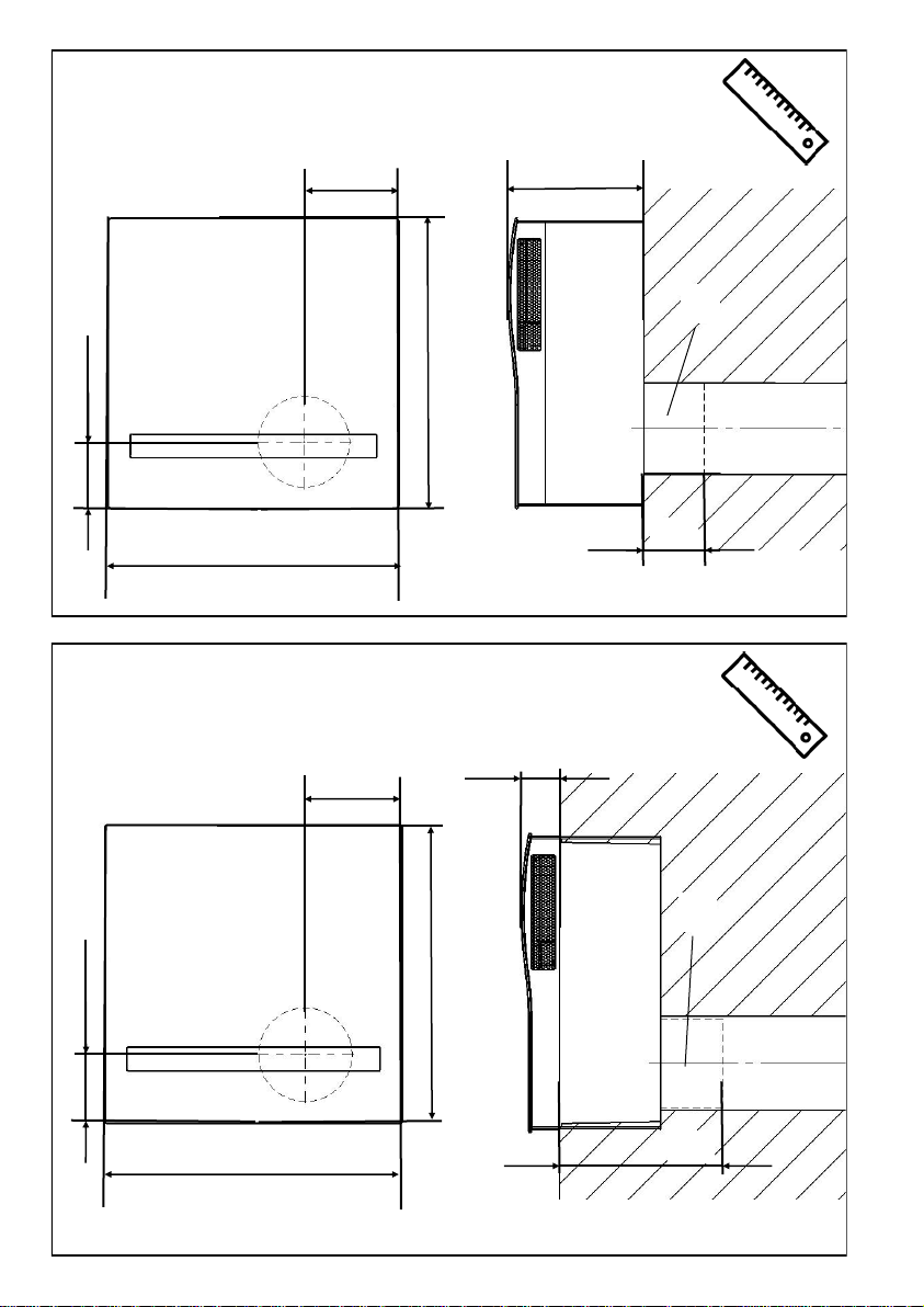
Maßbilder 11
Wandgehäuse Nexxt 11
Einbauposition, Montagebesonderheiten, 11
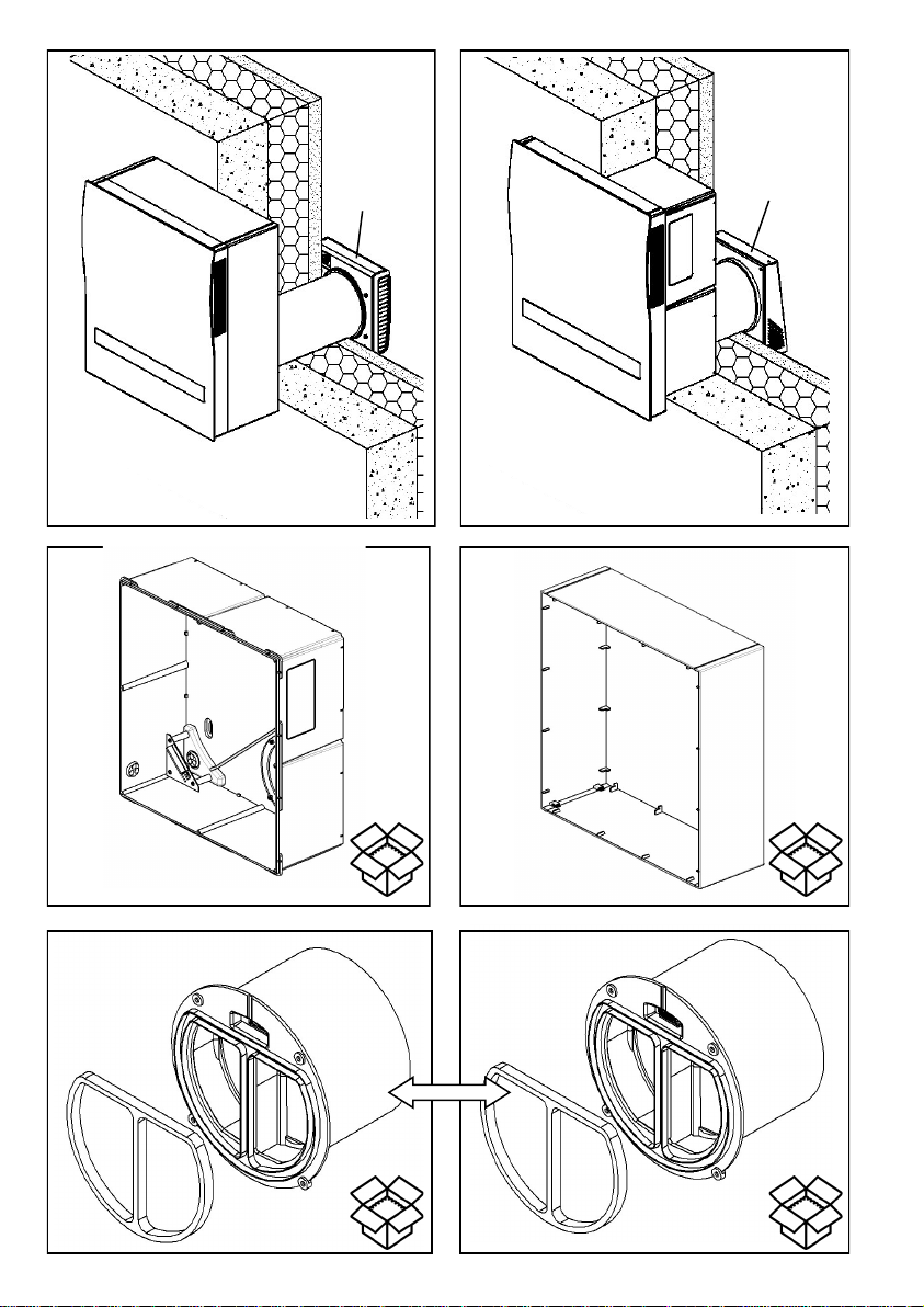
Einbaubeispiele, Versandeinheiten 11
Montage - Klappenverschluß 12
Montage - Aufputzmontage 12
Montage - Unterputzmontage 12
Montage - Montage Außenblenden 13
Elektrischer Anschluss - Anschlussbilder 13
• Diese Anleitung beschreibt die Aufputzmontage und Unterputzmontage der dezentralen Lüftungs-
geräte mit Wärmerückgewinnung Typ Nexxt
• Lesen Sie vor Montage diese Anleitung sorgfältig und vollständig durch! Beachten Sie unbedingt
die allgemeinen Sicherheitshinweise und die Sicherheitssymbole mit Hinweisen im Text.
• Diese Anleitung ist nach Abschluss der Montage an den Nutzer (Mieter, Eigentümer, Hausverwal-
tung usw.) weiterzugeben.
Zeichen in dieser Anleitung
Vorsicht! Jede Montagearbeit am Lüftungsgerät darf nur bei allpolig abgetrennter Netzspan-
nung erfolgen!
Achtung! Der elektrische Anschluss darf nur von autorisiertem Fachpersonal und nach gültiger
VDE 0100 vorgenommen werden!
Achtung! Dieses Gerät darf nicht von Kindern und Personen (Filterwechsel/Reinigung) bedient
werden, die aufgrund ihrer physischen, sensorischen oder geistigen Fähigkeiten oder ihrer
Unerfahrenheit oder Unkenntnis nicht in der Lage sind, es sicher zu bedienen. Kinder sollten
beaufsichtigt werden, um sicherzustellen, dass sie nicht mit dem Gerät spielen.
Temperatureinsatzbereich: - 15°C bis + 40°C
Einsetzbar bei einer relativen Luftfeuchte bis 65% im Innenraumbereich (nicht kondensierend). Bei
Überschreitung der Einsatzgrenzen Gerät ausschalten und Innenblende verschließen. Frischluftzu-
fuhr durch Fensterlüftung sicherstellen.
Entsteht Kondensat, wird dieses automatisch nach außen abgeführt. Achten Sie bitte im Winter da-
rauf, dass es zu keiner Eisbildung am Außengitter und im Bereich darum kommt.
Entsorgen Sie die Verpackung sortenrein. Wenn Sie sich vom Gerät trennen möchten, ent-
sorgen Sie es zu den aktuellen Bestimmungen. Auskunft erteilt die kommunale Stelle.
Dieses Zeichen warnt Sie vor Verletzungsgefahren.
Dieses Zeichen warnt Sie vor Verletzungsgefahr durch Elektrizität.
Gerätespannung: 200-240 V AC 50/60 Hz
Steuerspannung: 1 -10 V DC SELV
Elektrische Leistungsaufnahme: 5,7-40/46,5 W
Schutzart: IP 22
Volumenstrom: 15-110 m³/h
Einbauanleitung DE
Technische Daten
Inhalt Seite:
Sicherheitshinweise
Zu dieser Anleitung
Entsorgen
Einsatzbereich

11
Bild 1: Nexxt - Aufputz
Bild 2: Nexxt - Unterputz
(A) Adapter bzw. elektrischer Klappenverschluss
* in Bezug auf Blende
(alle Maße in mm)
Bild 3: ** Aussparung Wand min. 482 mm; *** Tiefe Ausschnitt min. 172 mm
(B) Netzanschluss Aufputz
(alle Maße in mm)
Achtung! Der umlaufende Kragen muss im fertigestellten Unterputzeinbau mit seiner Oberkante
putzbündig sein! Dies ist für die korrekte Funktion des Gerätes von entscheidender Bedeutung!
Montieren Sie das Lüftungsgerät mit einem empfohlenen seitlichen Mindestabstand von 30 cm und
einem empfohlenen Mindestabstand nach oben und nach unten von 15 cm.
Der seitliche Abstand dient zur Gewährleistung der Lüftungsfunktion, der Abstand nach oben und
nach unten der Montagefreiheit.
Wir empfehlen, das Gerät in einer Höhe von 1,50 m einzubauen, damit eine nutzerfreundliche Bedie-
nung gewährleistet ist.
(C) Fenster
• Das Lüftungsgerät muss im Innenraum lotrecht an einer Außenwand installiert werden.
• Es ist nur eine Einbaulage möglich und zwar mit oben befindlichen nach rechts und links
zeigenden Luftöffnungen.
• Das Lüftungsgerät muss für Betrieb und Wartung immer frei zugänglich sein, die Luftöffnun-
gen dürfen nicht zugebaut, verstellt oder abgedeckt werden
• Stellen Sie bei nachträglicher Montage sicher, dass im Bereich des Mauerdurchbruchs keine
Versorgungsleitungen (z.B. Gas, Wasser, Strom) liegen
• Stellen Sie sicher, dass der Mauerdurchbruch den statischen Erfordernissen vor Ort ent-
spricht, ziehen Sie ggf. einen Sturz ein.
Bild 5: Aufputzmontage
(D) Außenblende 1/EGA
Bild 6: Unterputzmontage
(E) Außenblende 1/HWE-2 oder 1/HAZ-2
Überprüfen Sie die Lieferung auf Vollständigkeit und einwandfreien Zustand!
Bild 7: Einbaugehäuse Typ 3/NXT
+ Putzschutzdeckel (= Bohrschablone), passives Übergangsstück inkl. Dichtung, EPP-
Adapter inkl. Dichtband und Schraubenzubehör
Bild 8: Aufputzset Typ 3/NXT-AP
Bild 9: passives Übergangsstück (liegt immer der Liefereinheit „Einbaugehäuse“ bei)
Bild 10: Elektrischer Klappenverschluss Typ 9/KVEN-2 Bestell.-Nr.: 40095
+ Schraubenzubehör
Bild 11: Rundkanal für Wanddurchführung
(F) Rohr DA 160 mm; (G) Putzschutzdeckel
Maßbilder (Bilder 1 und 2)
Wandgehäuse Nexxt (Bild 3)
Montagebesonderheiten
Einbaubeispiele (Bilder 5 und 6)
Einbauposition (Bild 4)
Versandeinheiten (Bilder 7 bis 12)

12
Bild 12: EPP-Adapter Typ 2/AD 160 Bestell-Nr.: 39965
Außenverschlüsse (wahlweise):
Bild 13: Außenblende Typ 1/EGA Bestell-Nr.: 40019
(H) Deckel; (I) Außenblende-Unterteil
+ Schraubenzubehör
Bild 14: Wetterschutzhaube Typen:
1/HWE-2 weiß Bestell-Nr.: 40107
1/HAZ-2 anthrazit Bestell-Nr.: 40108
(J) Abdeckung; (K) Rahmen; (L) Verbindungsschrauben
+ Schraubenzubehör
Bild 15: Setzen Sie die EPP-Adapter in der benötigten Länge auf den elektrischen Klappenver
schluss bzw. das passive Übergangsstück auf und dichten Sie alle Verbindungen (M) mit
dem beiliegenden Klebeband ab. Setzen Sie die Einheit aus EPP-Adaptern und elektri-
schem Klappenverschluss bzw. dem passiven Übergangsstück von innen in das Einbauge-
häuse ein und befestigen Sie diese mit den beiliegenden Schrauben.
Bild 16: Isolieren Sie die Enden des Kabel 5-7mm ab und schließen Sie den elektrischen Klappen-
verschluß an. ((N) rot; (O) schwarz; (P) weiß; (Q) gelb; (S) Kabel zum elektrischen Klappen-
verschluss)
Dem elektrischen Klappenverschluss liegt eine gesonderte Montageanleitung bei.
Die beiliegende Dichtung (R) wird zwischen die umlaufenden Rippen des elektrischen Klap-
penverschluss bzw. des passiven Übergangsstückes eingelegt. Es handelt sich dabei um
geschlossenzelligen EPDM Schaum, der kein Wasser zieht.
Der Anschluss muss Wasserdicht ausgeführt werden um das Eindringen von Kondensat
durch die Verbindung zu vermeiden.
Bild 17: Legen Sie mit Hilfe der Bohrschablone (= Putzschutzdeckel) die Positionen der Dübelbefes-
tigungen des Einbaugehäuses und die Position der Kernbohrung des Wanddurchführungs-
rohrs fest.
Stellen Sie die Kernbohrung für das Wanddurchführungsrohr her (Kernbohr Ø: 162 mm).
Bohren Sie die Löcher für die Wandbefestigungsdübel (Bohr Ø: 8mm).
Bitte beachten Sie die Abstände zu benachbarten Bauteilen/Wänden.
(T) Kabelaustritt
Bild 18: Stellen Sie das Netzkabel (und ggf. die Steuerleitungen) bereit:
Kabelaustritt aus der Wand nur im auf der Bohrschablone markierten Bereich (U).
Bild 19: Montieren Sie den Rundkanal innen und außen mit leichtem Überstand zur Überbrü- ckung
der Putzdicke. Halten Sie das in der Abbildung angegebene Gefälle ein. Dichten Sie den
Rundkanal umlaufend ab! (Montagekleber Bestell-Nr. 38733)
Putzen Sie das Rohr außen ein.
(V) innen; (W) außen; (X) Putzschutzdeckel
Bild 20: Setzen Sie das Aufputzset durch einfaches Zusammenstecken aus seinen vier Wandteilen
zusammen.
Schieben Sie das Einbaugehäuse in das Aufputzset ein.
Bild 21: Führen Sie das Netzkabel (und die Steuerleitungen) durch die rückseitige Kabeltülle in das
Einbaugehäuse ein.
Befestigen Sie das Einbaugehäuse zusammen mit dem aufgesetzten Aufputzset an der
Wand.
Achten Sie dabei darauf, dass der elektrische Klappenverschluss exakt in das Wandeinbau-
rohr eingepasst wird.
Bild 22: Nehmen Sie die Netzanschlussplatine aus dem Einbaugehäuse und setzen Sie diese
nach erfolgtem Netzanschluss wieder ein.
Schließen Sie das Netzkabel (und die Steuerleitungen) an.
Elektrischer Anschluss siehe Kapitel „Elektrischer Anschluss - Anschlussbilder“.
Vorsicht! Jede Montagearbeit am Lüftungsgerät darf nur bei allpolig abgetrennter Netzspan-
nung erfolgen!
Montage - Aufputzmontage (Bilder 17 bis 22)
Montage - Klappenverschluß (Bilder 15 und 16)

13
Bild 23: Legen Sie mit Hilfe des Einbaugehäuses die Position der Kernbohrung für das Wanddurch-
führungsrohr fest. Stellen Sie die Kernbohrung für das Wanddurchführungsrohr her.
Bild 24: Montieren Sie das Wanddurchführungsrohr innen wandbündig zur Wandöffnung, außen mit
leichtem Überstand zur Überbrückung der Außenputzdicke. Halten Sie das in der Abbildung
angegebene Gefälle ein. Putzen Sie das Rohr außen ein.
Bild 25: Setzen Sie das Einbaugehäuse in den Wandausschnitt ein. Achten Sie darauf, dass der
elektrische Klappenverschluss exakt in das Wanddurchführungsrohr eingepasst wird. Rich-
ten Sie den umlaufenden Kragen des Einbaugehäuses wie abgebildet putzbündig (Y) aus.
Fixieren Sie das Einbaugehäuse im Wandausschnitt (z.B. mit nichttreibendem
Bauschaum).
Bild 26: Schlitzen Sie den Kabelkanal für das Netzkabel (und ggf. die Steuerleitungen).
Führen Sie Netzkabel (und Steuerleitungen) durch die seitliche Kabeltülle in das Einbauge-
häuse ein.
(Y) Kabellänge: ca. 20 cm
Bild 27: Schließen Sie Netzkabel (und Steuerleitungen) an.
Nehmen Sie dazu ggf. die Netzanschlussplatine aus dem Einbaugehäuse und setzen Sie
diese nach erfolgtem Netzanschluss wieder ein.
Elektrischer Anschluss siehe Kapitel „Elektrischer Anschluss - Anschlussbilder“.
Vorsicht! Jede Montagearbeit am Lüftungsgerät darf nur bei allpolig abgetrennter Netzspan-
nung erfolgen!
Die Montage der Außenblenden 1/EGA und der Wetterschutzhauben 1/HWE-2 bzw. 1/HAZ-2
erfolgt entsprechend den diesen Teilen beiliegenden Montageanleitungen.
Vorsicht! Jede Montagearbeit am Lüftungsgerät darf nur bei allpolig abgetrennter Netzspan-
nung erfolgen!
Machen Sie vor Anschluss des Lüftungsgerätes an die Netzspannung alle Anschlussleitungen
spannungsfrei! (Abtrennung vom Netz mit mindestens 3 mm Kontaktöffnung, z.B. allpolig tren-
nende elektr. Sicherung).
Jeder zu diesem Lüftungssystem gehörende Stromkreis muss mit einem Fehlerstromschutz
(z.B. FI-Schalter) ausgestattet sein!
Elektrischer Anschluss nur durch Fachmann!
Sicherheitshinweise
Verwenden Sie als Netzkabel maximal NYM-J 5 x 1,5 mm²! Der Anschluss des PE-Leiters ist unbe-
dingt notwendig!
Zur Anbindung der TAC und/oder der Gestensteuerung benutzen Sie Kabel des Typs J-Y(St)Y
(2x2x0,8), max. 1,5 mm²! Die Anschlusslitzen für den elektrischen Klappenverschluss sind werkssei-
tig beigelegt!
Netzanschlussleiterplatte und Netzanschlussklemmen sind zur Unterstützung beschriftet!
Keinesfalls eines der schon an die Netzanschlussplatine werksseitig angeschlossenen Kabel lösen!
Weitere Anschlussbilder auf Anfrage!
Bild 28: Betrieb über das Bedienelement am Gerät und Darstellung der verschiedenen Anschluss-
möglichkeiten je nach Verfügbarkeit
(Z1) zum elektrischen Klappenverschluss 9/KVEN-2
(Z2) zur Gestensteuerung 5/GS
(Z3) zur TAC, KNX Control 4 bzw. 0 - 10 V
(Z4) Netzanschluss
((N) rot; (O) schwarz; (P) weiß; (Q) gelb)
Montage - Unterputzmontage (Bilder 23 bis 27)
Montage - Montage Außenblenden
Elektrischer Anschluss - Anschlussbilder (Bilder 28 bis 30)

14
Bild 29: Manuelles Schalten der Volumenstromstufen über einen externen zweipoligen Taster:
L1 = Volumenstromstufe größer; L2 = Volumenstromstufe kleiner
Hinweis: DIP-Schalter 2 muss hierfür in Position OFF sein.
((Z5) Brücke; (Z6) 2-Wippentaster zweipolig)
Bild 30: Manuelles Schalten der Volumenstromstufen über einen externen einpoligen Taster an L1
und gleichzeitigem Betrieb von einem oder mehreren Abluftventilatoren über Kopplung an L2
zum Ausgleich des durch die Abluftventilatoren entstehenden zusätzlichen Unterdrucks.
L1: 1x Tasten: Volumenstromstufe grösser; 2x Tasten: Volumenstromstufe kleiner
Hinweis: DIP-Schalter 2 muss hierfür in Position ON sein.
((Z7) Schalter zweipolig; (Z8) Taster einpolig)

15
About this manual, Safety instructions, Technical data, Range of application, Disposal 15
Dimension drawings 16
Wall housing Nexxt 16
Installation position, Special mounting features 16
Installation examples, Shipping units 16
Installation - Flap closure 17
Installation - Surface mounting 17
Installation - Flush mounting 17
Installation - Outer screens 18
Electrical connection - Connection diagrams 18
Dispose of the packaging correctly sorted. If you wish to dispose of the device, please follow
the current regulations. Information is available from your local authority.
• These instructions describe surface mounting and flush mounting of the decentralised ventilation
units with heat recovery type Nexxt.
• Read this manual carefully and completely prior to installation! Always observe the general safety
instructions and the safety symbols with information in the text.
• Hand out this manual to the user (tenants, proprietors, property management etc.) after comple-
ting assembly.
Symbols in this manual:
Caution! Any installation work on the ventilation unit may only be carried out with the mains
voltage disconnected at all poles!
Attention! The electric connection may only be made by authorised qualified personnel and
according to the applicable version of VDE 0100!
Attention! This unit must not be operated (filter change/cleaning) by children or persons who
are not capable of operating it safely due to their physical, sensory or mental abilities or their
lack of experience or knowledge. Children should be supervised to ensure that they do not play
with the unit.
This symbol warns you against risks of injury
This symbol warns you against risks of injury from electricity
Unit voltage: 200-240 V AC 50/60 Hz
Control voltage: 1 -10 V DC SELV
Electrical power consumption: 5.7-40/46.5 W
Protection class: IP 22
Volume flow: 15-110 m³/h
Temperature application range: - 15°C to + 40°C
Can be used at a relative humidity of up to 65% indoors (non-condensing).The user is requested to
switch off the unit and close the inner screen if the application limits are exceeded. Ensure a supply
of fresh air by window ventilation.
If condensate is produced, it is automatically discharged to the outside. In winter, please ensure that
there is no ice formation on the outer grille and in the area around it.
Installation Manual EN
Contents Page:
Range of application
About this manual
Technical data
Safety instructions
Disposal

16
Figure 1: Nexxt - surface mounting
Figure 2: Nexxt - flush mounting
A) Adapter or electrical flap closure
* in terms of screen
(All dimensions in mm)
Figure 3: ** recess wall min. □ 482 mm; *** depth of cut-out min. 172 mm
(B) mains connection surface mounting
(All dimensions in mm)
Caution! The upper edge of the circumferential collar must be flush with the plaster in the finished
flush-mounted installation! This is of decisive importance for the correct functioning of the unit!
Install the ventilation unit with a recommended minimum lateral distance of 30 cm and a recom-
mended minimum upward and downward distance of 15 cm.
The lateral distance is required to ensure the ventilation function; the distance upwards and down-
wards is required to ensure freedom of installation.
We recommend that the unit be installed at a height of 1.50 m to ensure user-friendly operation.
(C) window
• Indoors, the ventilation unit must be installed vertically on an outer wall.
• There is only one installation position possible - with the air openings at the top pointing to
the right and left.
• The ventilation unit must always be freely accessible for operation and maintenance; the air
openings must not be blocked or covered.
• In case of subsequent installation, make sure that there are no supply lines (e.g. gas, water,
electricity) in the area of the wall breakthrough
• Make sure that the wall breakthrough corresponds to the static requirements on site, if neces-
sary install a lintel.
Figure 5: Surface mounting
(D) outer screen 1/EGA
Figure 6: Flush mounting
(E) outer screen 1/HWE-2 or 1/HAZ-2
Check the delivery for completeness and mint condition!
Figure 7: Installation housing type 3/NXT
+ plaster protection cap (= drilling template), passive transition piece incl. seal,
EPP adapter incl. sealing tape and screw accessories
Figure 8: Surface-mounting set type 3/NXT-AP
Figure 9: Passive transition piece (always included with the delivery unit "installation housing")
Figure 10: Electric flap closure type 9/KVEN-2 Order No.: 40095 + screw accessories
Figure 11: Wall-tube for wall ducting
(F) pipe DA 160 mm; (G) plaster protection cap
Shipping units (Figures 7 to 12)
Installation position (Figure 4)
Installation examples (Figures 5 and 6)
Special installation features
Wall housing Nexxt (Figure 3)
Dimension drawings (Figures 1 and 2)

17
Figure 12: EPP adapter type 2/AD 160 Order No.: 39965
External closures (optional):
Figure 13: Outer screen type 1/EGA Order No.: 40019
(H) cover; (I) lower part of outer screen
+ screw accessories
Figure 14: Weather protection hood types:
1/HWE-2 white Order No.: 40107
1/HAZ-2 anthracite Order No.: 40108
(J) cover; (K) frame; (L) connecting screws
+ screw accessories
Figure 15: Place the EPP adapters in the required length on the electrical flap closure or the passive
transition piece and seal all connections (M) using the enclosed adhesive tape. Insert the
unit consisting of EPP adapters and electrical flap closure or the passive transition piece
from the inside into the installation housing and fasten it using the enclosed screws.
Figure 16: Strip the ends of the cable (5-7mm) and connect the electrical flap closure.
((N) red; (O) black; (P) white; (Q) yellow; (S) cable for the electrical flap closure)
Separate installation instructions are enclosed with the electrical flap closure.
The enclosed seal (R) is inserted between the circumferential ribs of the electrical flap
closure or the passive transition piece. It is a closed-cell EPDM foam which does not draw
water.
The connection must be watertight to prevent condensation from entering through the
connection.
Figure 17: Use the drilling template (= plaster protection cover) to determine the positions of the
dowel fastenings of the installation housing and the position of the core drill hole of the
wall duct).
Make the core drill for the wall duct (core drill Ø: 162 mm).
Drill the holes for the wall fixing dowels (drill Ø: 8mm).
Please observe the distances to adjacent components/walls.
(T) cable outlet
Figure 18: Provide the power cable (and the control cables, if required):
Cable outlet from the wall only in the area (U) marked on the drilling template.
Figure 19: Install the wall-tube inside and outside with a slight projection to bridge the plaster thick-
ness. Observe the slope shown in the figure. Seal the wall-tube all around! (Mounting
adhesive Order No. 38733)
Plaster the outside of the pipe.
(V) inside; (W) outside; (X) plaster protection cap
Figure 20: Assemble the surface-mounted set from its four wall parts by simply pushing them toge-
ther.
Slide the installation housing into the surface-mounted set.
Figure 21: Insert the power cable (and the control lines) through the cable grommet on the back into
the installation housing.
Fasten the installation housing together with the attached surface-mounted set to the wall.
Make sure that the electrical flap closure fits exactly into the wall installation pipe.
Figure 22: Remove the mains connection board from the installation housing and reinsert it after the
mains connection has been completed.
Connect the mains cable (and the control lines).
For electrical connection, see chapter "Electrical connection - connection diagrams".
Caution! Any installation work on the ventilation unit may only be carried out with
the mains voltage disconnected at all poles!
Installation - Flap closure (Figures 15 and 16)
Installation - Surface mounting (Figures 17 to 22)

18
Figure 23: Use the installation housing to determine the position of the core drill hole for the wall
duct. Make the core bore for the wall duct.
Figure 24: Mount the wall duct on the inside flush with the wall to the wall opening, on the outside
with a slight projection to bridge the exterior plaster thickness. Observe the slope shown
in the figure. Plaster the pipe on the outside.
Figure 25: Insert the installation housing into the wall cut-out. Make sure that the electrical flap clo-
sure fits exactly into the wall duct. Align the circumferential collar of the installation hou-
sing flush with the plaster (Y) as shown.
Fix the installation housing in the wall cut-out (e.g. by using non-driving construction fo-
am).
Figure 26: Slot the cable duct for the power cable (and the control lines, if required).
Insert the power cable (and control lines) through the cable grommet on the side into the
installation housing.
(Y) cable length: approx. 20 cm
Figure 27: Connect power cables (and control lines).
For this purpose, remove the mains connection board from the installation housing, if
necessary, and reinsert it after the mains connection has been made.
For electrical connection, see chapter "Electrical connection - connection diagrams".
Caution! Any installation work on the ventilation unit may only be carried out with the
mains voltage disconnected at all poles!
The outer screens 1/EGA and the weather protection hoods 1/HWE-2 or 1/HAZ-2 are to be
installed according to the installation instructions enclosed with these parts.
Caution! Any installation work on the ventilation unit may only be carried out with the mains
voltage disconnected at all poles!
Before connecting the ventilation unit to the mains voltage, disconnect all connecting cables
from the power supply! (Disconnect from the mains with at least 3 mm contact opening, e.g. all-
pole disconnecting electrical fuse).
Each circuit belonging to this ventilation system must be equipped with residual current protec-
tion (e.g. RCD)!
Electrical connection only by a specialist!
Additional installations and electrical components in this ventilation system are not admissible!
Safety instructions
As power cable, use a maximum size of NYM-J 5 x 1.5 mm²! It is absolutely necessary to connect
the PE conductor!
To connect the TAC and/or the gesture control, use cable type J-Y(St)Y (2x2x0.8), max. 1.5 mm²!
The connecting wires for the electrical flap closure are included in the delivery!
Mains connection circuit board and mains connection terminals are labelled for your convenience!
Never disconnect any of the cables that have already been connected to the mains connection board
by the manufacturer!
Further connection diagrams on request!
Figure 28: Operation via the control element on the unit and illustration of the different connection
options depending on availability
(Z1) for electrical flap closure 9/KVEN-2
(Z2) for gesture control 5/GS
(Z3) for TAC, KNX Control 4 or 0 - 10 V
(Z4) mains connection
((N) red; (O) black; (P) white; (Q) yellow)
Installation - Flush mounting (Figures 23 and 27)
Installation - Outer screens
Electrical connection - Connection diagrams (Figures 28 and 30)

19
Figure 29: Manual switching of the volume flow stages via an external two-pole push-button:
L1 = volume flow stage higher; L2 = volume flow stage lower
Note: For this purpose, DIP switch 2 must be in the OFF position.
((Z5) bridge; (Z6) double-pole 2 rocker switch)
Figure 30: Manual switching of the volume flow stages via an external single-pole push-button at L1
and simultaneous operation of one or more exhaust air fans via coupling at L2 to com-
pensate for the additional negative pressure created by the exhaust air fans.
L1: 1x push-buttons: volume flow stage higher; 2x push-buttons: volume flow stage lower
Note: For this purpose, DIP switch 2 must be in the ON position.
((Z7) double-pole switch; (Z8) single-pole push button)

20
Notes
E279 02.22
Vertrieb Schweiz durch
WESCO AG
Schul-, Büro- und Wohnungslüftung
Tägerhardstrasse 110 Tel. +41 (0)56 438 12 12
CH-5430 Wettingen balance@wesco.ch
Table of contents
Languages:
Popular Fan manuals by other brands

Swegon
Swegon ILTO X100 Premium Instructions for installation, use and maintenance

Haier
Haier HACI-RP DX Series Installation, use and maintenance manual

Euramco
Euramco RAMFAN FlowPath UB20 Series technical information

Mercury
Mercury 450.007UK user manual

Emerson
Emerson CF205BS01 owner's manual

MALTEC
MALTEC WK300Wt instruction manual

Casablanca
Casablanca Brescia Casablanca Brescia Gallery Edition owner's manual

emerio
emerio FN-110139 instruction manual

Central Machinery
Central Machinery 47755 Owner's manual & safety instructions

Elco Klockner
Elco Klockner EK03B G Assembly instructions

QuietCool
QuietCool AFG SLR-40 owner's guide

Faro Barcelona
Faro Barcelona Tonic manual