Westinghouse PT30125 User manual

INSTRUCTION MANUAL
PT30125
3/4" ROTARY HAMMER DRILL
NOTE: Before operating this tool, read this manual
and follow all safety rules and operating instructions.
120V
60Hz CUS
4.2A
650W
3/4
INCH rpm
0~2,050

2
23
34
11 8
9
5
7
6
10
12
The numbering of the product features refers to
the illustration of the machine on the graphics.
1. Chuck
2. SDS-plus tool holder
3. Dust protection cap
4. Locking sleeve
5. Rotational direction switch
6. Lock-on button for On/Off switch
7. On/Off switch
8. Release button for mode selector switch
9. Mode selector switch
10. Button for RPM adjustment
11. Auxiliary handle
12. Handle

3
FIG. 12
FIG. 8
FIG. 14

MACHINE SPECIFIC SAFETY WARNING
4
1) Machine Specific Safety Warnings
Wear hearing protection. Exposure to noise can
cause hearing loss.
Always use the auxiliary handle supplied with the
machine. Loss of control can cause personal
injury.
Use suitable detectors to determine if utility lines
are hidden in the work area or call the local utility
company for assistance. Contact with electric
lines can lead to fire and electric shock. Dama-
ging a gas line can lead to explosion. Penetrating
a water line causes property damage or may
cause an electric shock.
Hold the power tool only by the insulated gripping
surfaces when performing an operation where the
cutting tool may contact hidden wiring or its own
cord. Contact with a “live” wire will also make
exposed metal parts of the power tool “live” and
shock the operator.
When working with the machine, always hold it
firmly with both hands and provide for a secure
stance. The power tool is guided more secure
with both hands.
Secure the workpiece. A workpiece clamped with
clamping devices or in a vice is held more secure
than by hand.
Do not work materials containing asbestos.
Asbestos is considered carcinogenic.
Take protective measures when dust can develop
during working that is harmful to one’s health,
combustible or explosive. Example: some dusts
are regarded as carcinogenic. Wear a dust mask
and work with dust/chip extraction when
connectable.
Keep your workplace clean. Blends of materials
are particularly dangerous. Dust from light alloys
can burn or explode.
Always wait until the machine has come to a
complete stop before placing it down. The tool
insert can jam and lead to loss of control over the
power tool.
Never use the machine with a damaged cable
and pull the mains plug when the cable is
damaged while
working. Damaged cables increase the risk of an
electric shock.
2) Functional Description
Read all safety warnings and all instructions.
Failure to follow the warnings and instructions
may result in electric shock, fire and/or serious
injury.
While reading the operating instructions, unfold
the graphics page for the machine and leave it
open.
a) Intended Use
The machine is intended for hammer drilling in
concrete, brick steel and wood. It is also suitable
for drilling without impact in wood, metal, ceramic
and plastic. Machines with electronic control and
right/left rotation are also suitable for screw
driving and thread cutting.
b) Product Features
The numbering of the product features refers to
the illustration of the machine on the graphics.
1. Chuck
2. SDS-plus tool holder
3. Dust protection cap
4. Locking sleeve
5. Rotational direction switch
6. Lock-on button for On/Off switch
7. On/Off switch
8. Release button for mode selector switch
9. Mode selector switch
10. Button for RPM adjustment
11. Auxiliary handle
12. Handle
3) Assembly
Before any work on the machine itself, pull the
mains plug.
a) Auxiliary Handle
Operate your machine only with the auxiliary
handle 11.

OPERATION INSTRUCTION
5
Rotating the Auxiliary Handle, the auxiliary handle
11 can be set to any position for a secure and
low-fatigue working posture.
Turn the bottom part of the auxiliary handle 11 in
counterclockwise direction and swivel the
auxiliary handle 11 to the desired position. Then
retighten the bottom part of the auxiliary handle
11 by turning in clockwise direction.
Pay attention that the clamping band of the
auxiliary handle is positioned in the groove on the
housing as intended for.
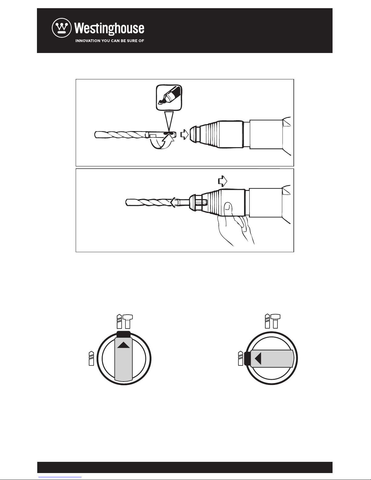
b) Changing the Tool
The dust protection cap 3 largely prevents the
entry of drilling dust into the tool holder during
operation. When inserting the tool, take care that
the dust protection cap 3 is not damaged.
A damaged dust protection cap should be
changed immediately. We recommend having
carried out by an after-sales service.
Inserting SDS-plus Drilling Tools, the SDS drill
chuck allows for simple and convenient changing
of drilling tools without the use of additional tools.
Clean and lightly grease the shank end of the
tool. Insert the tool in a twisting manner into the
tool holder until it latches itself.
Check the latching by pulling the tool.
As a requirement of the system, the SDS drilling
tool can move freely. This causes a certain radial
run-out at no-load, which has no effect on the
accuracy of the drill hole, as the drill bit centre
itself upon drilling.
Removing SDS Drilling Tools, push back the
locking sleeve 4 and remove the tool.
4) Operation
1. Starting Operation
Observe correct mains voltage! The Voltage of
the power source must agree with the voltage
specified on the nameplate of the machine.
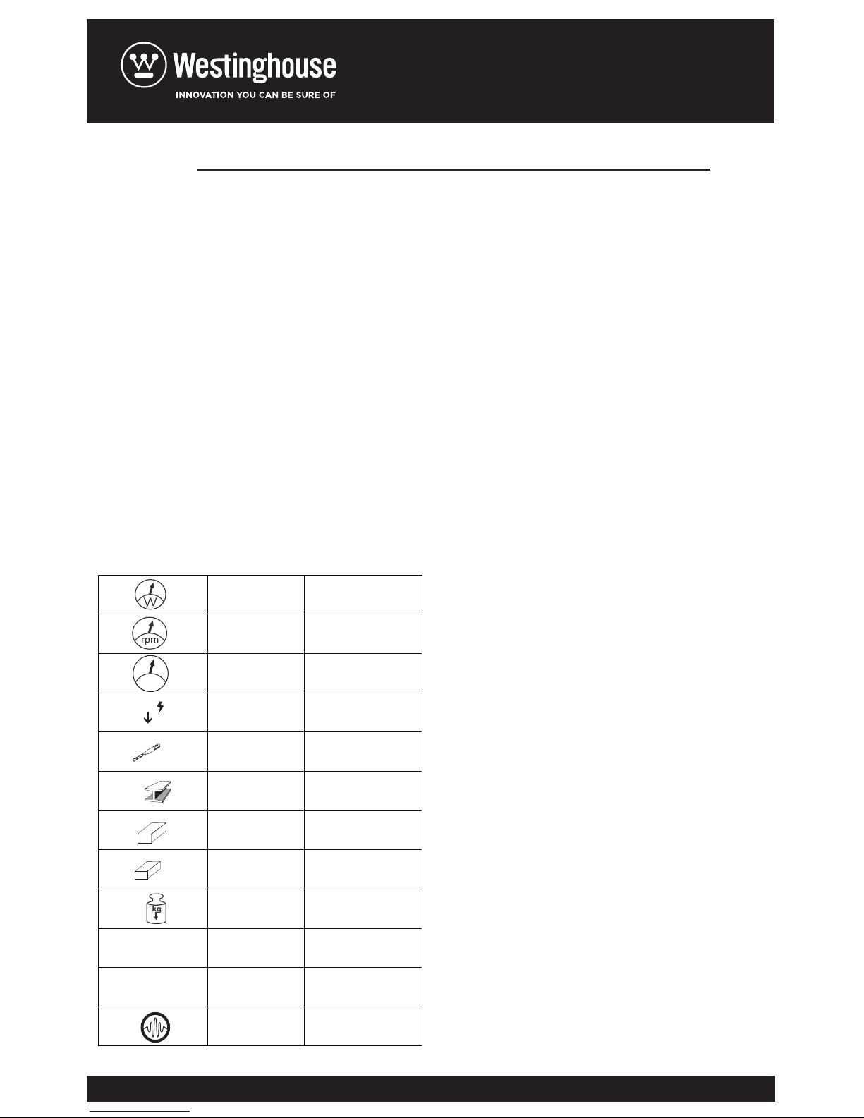
Setting the Operating mode, with the selector
switch for drilling/ hammer drilling 9, the operating
mode of the machine is selected. To change the
operating mode, press the release button 8 and
turn the drilling/ hammer drilling selector switch 9
to the desired position until can be heard to latch.
Note: only change the mode of operation while
disconnected from the machine! Otherwise you
may damage the machine.
Position for hammer drilling in concrete (fig.12).
Position for drilling without impact in wood, metal,
ceramic and plastic as well as for screw driving
and thread cutting. (fig.14).
Reversing the rotational direction, the rotational
direction switch 5 is used to reverse the rotational
direction of the machine. However, this is not
possible with the On/Off switch 7 actuated.
Right rotation: turn the selector switch for
drilling/hammer drilling 5 on both sides to the stop
in the position.
Left rotation: turn the selector switch for
drilling/hammer drilling 5 on both sides to the stop
in the position.
Set the direction of rotation for hammer drilling,
drilling and chiseling always to right rotation.
Switching On and Off, to start the machine, press
the On/Off switch, keep it pressed and additiona-
lly push the lock-on button 6. To switch off the
machine, release the On/Off switch 7.
When the On/Off switch 7 is locked, press it first
and then release it.
Setting the Speed/ Impact Rate, the speed/impact
rate of the switched on power tool can be variably
adjusted, depending on how far the On/Off switch
7/10 is pressed.
Light pressure on the On/Off switch 7/10 results
in low speed/impact rate. Further pressure on the
switch increases the speed/ impact rate.

6
OPERATION INSTRUCTION
Safety Clutch
If the tool insert becomes caught or jammed, the
drive to the drill spindle is interrupted. Because of
the forces that occur, always hold the power tools
firmly with both hands and provide for a secure
stance.
If the power tool jams, switch the machine off and
loosen the tool insert. When switching the
machine on with the drilling tool jammed, high
reaction torques can occur.
Switching On/Off: A
To start the machine, press the On/Off switch 6
and keep it depressed. To switch off the machine,
release the On/Off switch 6.
Setting the Speed/Impact Rate
The electronic control 10 enables stepless speed
and impact pre-selection in accordance with the
material to be worked.
The maximum hammering capacity is achieved
when the thumbwheel 10 is set to position “6”.
5) Maintenance and Service
a. Maintenance and Cleaning
Before any work on the machine itself, pull the
mains plug.
For safe and proper working, always keep the
machine and ventilation slots clean.
A damaged dust protection cap should be
changed immediately. We recommend having this
carried out by an after-sales service.
Clean the tool holder 2 each time after using.
Important:
When the carbon brushes wear below acceptable
service tolerances, the machine will automatically
cut out. The machine must be sent to customer
service for maintenance.
If the machine should fail despite the care taken
in manufacturing and testing procedures, repair
should be carried out by an after-sales service
centre for power tools.
In all correspondence and spare parts order,
please always include the article number given on
the type plate of the machine.
b. Disposal
We recommend subjecting electric tools,
accessories and packaging to a recovery process
that respect the environment.
Do not throw away electric tools!
Subject to change without notice.
c. Technical data
= Power input
= Load Speed
= Percussion
= Percusive energy
= Insertion
= Maximum drilling, steel
= Maximum drilling, concrete
= Maximum drilling, wood
= Weight
= Sound power level WA
= Sound pressure level P
= Vibration
ipm
e
STEEL
CONCRET
WOOD
LWA
LpA
for EU countries only: in accordance with
European Directive 2202/96/EC on
unserviceable electric and electronic
apparatus, after transportation into
national law, electric tools must be
collected separately to subject them to
ecologic recycling.

7
OPERATION INSTRUCTION
The values given are valid for nominal voltages
(U) 110/120v – 60Hz. For lower voltage and
models for specific countries, these values can
vary. Please observe the article number on the
type plate of your machine. The trade names of
the individual machines may vary.
d. Declaration of conformity
We declare under our own responsibility that the
product as describe under “Technical Data” is in
conformity with the following standards or
standardized documents:
EN 60745-1:2010/A11:2011, UNE EN 60745-2-
6:2011, EN 55014-1:2006, EN 61000-3-2:2006,
EN 61000-3-3:1995+A 1:2001+A2:2005, EN ISO
3744:1995 in accordance with the provisions in
Directives 2004/108/EC, 2006/42/EC,
2000/14/EC.
General information:
W 650
Min-1 0-2100
Min-1 0-5770
J2.2
SDS- PLUS
@ max 13mm
@max 18mm
@ max 30mm
Kg 1.8
Lpa dB (A) 83
Lwa dB (A) 98
Ah m/s2 10
ipm
e
STEEL
CONCRET
WOOD
LWA
LpA

8
PART LIST
1
2
3
4
5
6
7
8
9
10
11
12
13
14
15
16
17
18
19
20
21
22
23
24
25
26
27
28
29
30
31
32
33
34
Front cover
Clip ring
Steel ball block
Steel ball block plate
Steel ball support plate
Steel ball block spring
Gear box
Screw
Oil seal
Bearing 61805-2RS
Bearing 606-2Z
Clip ring
Spring washer
Spring
Big gear
Steel ball
Rotary sleeve
Needle
Clutch base
Clutch Washer
Impact rod
Lead sleeve
shock absorption ring
O ring
Impact hammer sleeve
Clip ring
Air hammer
O ring
Cylinder
Cylinder pin
Cylinder flat washer
Oil bearing
Middle cover ring
Middle cover
Felted wool
Small gear
Hammer clutch
Middle axis
Steel ball
Swinging rod bearing
Needle bearing
N°. 1 gear
Bearing press plate
Bearing 607-2Z
Opening blck circle
Pick spring
Hammer grade pick
Lead pillar
Screw
Spring washer
O ring
Oil proof cover
Bearing 608-Z
Rotor
Bearing 626-2Z
Fan guider
Screw
Stator
Housing
Brush cover
Carbon brush
Carbon brush copper
Brush shelf
Dust proof switch
Left handle
capacitance
Binding post
Indicator light for power
35
36
37
38
39
40
41
42
43
44
45
46
47
48
49
50
51
52
53
54
55
56
57
58
59
60
61
62
63
64
65
66
67
68
Screw
Cable press plate
Cable sleeve
Cable
Screw
Right handle
Button
Buton spring
External knob
O ring
Handle assembled
69
70
71
72
73
74
75
76
77
78
501
N° PART NAME PART NAME PART NAMEN° N°

9
EXPLODED VIEW

Table of contents
Other Westinghouse Drill manuals
Popular Drill manuals by other brands

Makita
Makita HP330D user guide

FE Powertools
FE Powertools 150 RLX Operator's manual

Pattfield Ergo Tools
Pattfield Ergo Tools PE-800 TBM Original instructions

EIBENSTOCK
EIBENSTOCK 18EHB 16/1.4 S R/L Original instructions

Hilti
Hilti DD-400E operating instructions

Parkside
Parkside PEBH 1010 - 2 Operation and safety notes

Fein
Fein ASKEU 636 Kin parts manual

Central Machinery
Central Machinery CENTRAL MACHINERY 44505 Set up and operating instructions

AEG
AEG MH 7 E Original instructions

Sparky Group
Sparky Group BU2 201 Original instructions

GÜDE
GÜDE BS 20-201-24 K Translation of the original instructions

Metabo
Metabo B 650 Original instructions