Whalen LLAVC54T User manual

THIS INSTRUCTION BOOKLET CONTAINS IMPORTANT SAFETY INFORMATION.
PLEASE READ AND KEEP FOR FUTURE REFERENCE.
Whalen Furniture Mfg., Inc. Page 1 Factory No. 15548
54" TV Console
Model # LLAVC54T
ADULT ASSEMBLY REQUIRED
If you have any questions regarding assembly or if parts are missing, DO NOT return this item to the store
where it was purchased. Please call our toll-free customer service number and have your instructions and parts
list ready to provide the model name, part name or factory number:
1-866-942-5362 8:30 a.m. - 4:30 p.m. PST, Monday - Friday
ONLINE: www.whalenfurniture.com EMAIL: parts@whalenfurniture.com
Video Instruction Guides
Go to http://whalen.showuhow.com to view step-by-step instructional videos
for assembling and installing your product. Enter the following product number
on the ShowUhow homepage.
LOT NUMBER:
DATE PURCHASED: / /
LLAVC54T

Model # LLAVC54T
Please call for replacement parts or assistance: 1-866-942-5362
Whalen Furniture Mfg., Inc. Page 2 Factory No. 15548
MANUFACTURER: Whalen Furniture
CATALOG: 54" TV Console (LLAVC54T)
DATE OF MANUFACTURE: November 2012
MADE IN CHINA
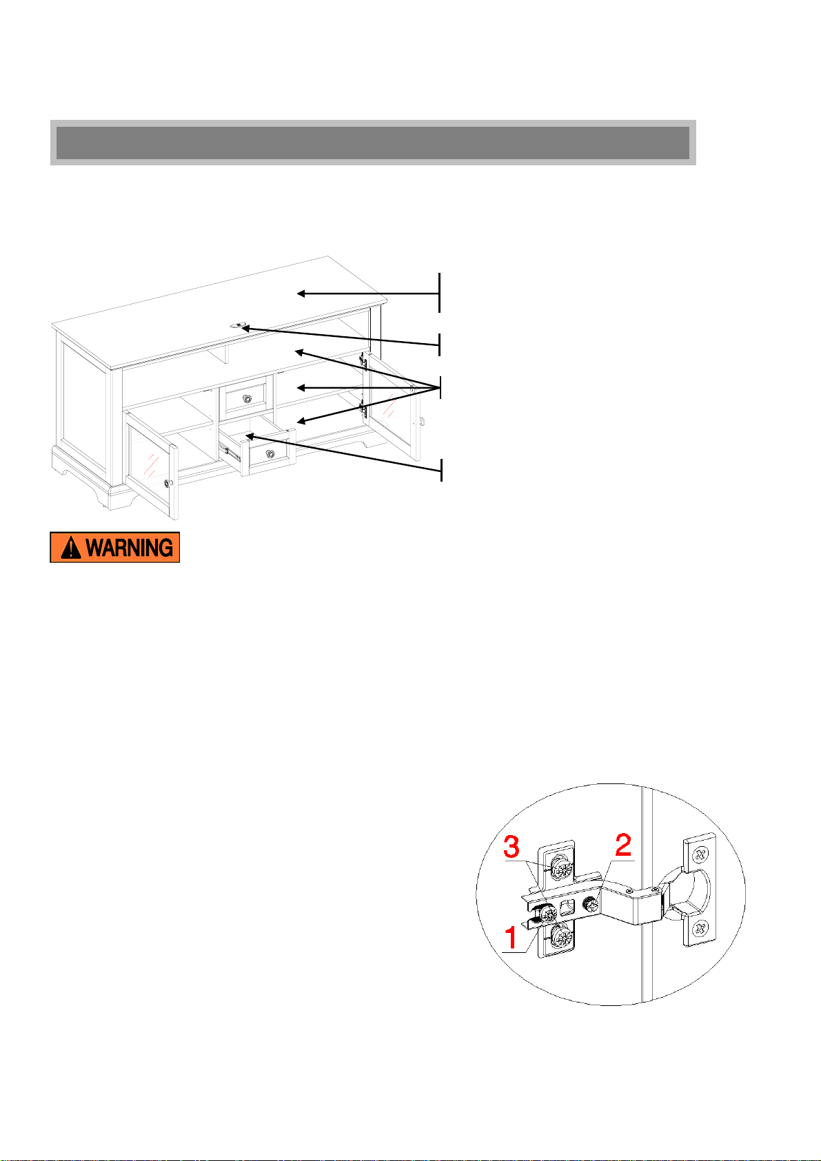
How to adjust the European adjustable hinges on doors
Shipping may cause doors to go out of alignment. If you find that the doors need to be adjusted slightly,
turn the appropriate screw, as illustrated.
1. TO ADJUST DOOR FORWARD OR BACKWARD.
2. TO ADJUST DOOR TO RIGHT OR TO LEFT.
3. TO ADJUST DOOR UP OR DOWN.
MAXIMUM RECOMMENDED WEIGHT LOADS
MAXIMUM LOAD 50 lb. (22.7 kg)
MAXIMUM LOAD 15 lb. (6.8 kg)
FITS UP TO MOST 60” FLAT PANEL TVs
MAXIMUM LOAD 135 lb. (61.2 kg)
THIS UNIT IS NOT INTENDED FOR USE WITH CRT TVS. USE ONLY WITH
FLAT PANEL TVS AND AUDIO/VIDEO EQUIPMENT MEETING RECOMMENDED SIZE AND
WEIGHT LIMITS. NEVER USE WITH LARGER/HEAVIER THAN RECOMMENDED FLAT
PANEL TVS OR EQUIPMENT. TO AVOID INSTABILITY, PLACE FLAT PANEL TV IN
CENTRE OF THE UNIT; CRT TVS, IMPROPERLY POSITIONED FLAT PANEL TVS, OR FLAT
PANEL TVS OR OTHER EQUIPMENT THAT EXCEED RECOMMENDED SIZE AND WEIGHT
LIMITS COULD FALL OFF OR BREAK THE UNIT
,
CAUSING POSSIBLE SERIOUS INJURY.
PLACE TV BEHIND THE STOPPER

Model # LLAVC54T
Please call for replacement parts or assistance: 1-866-942-5362
Whalen Furniture Mfg., Inc. Page 3 Factory No. 15548
Important
Before you begin: Open, identify and count all parts prior to assembly. Lay out parts on a flat and non-
abrasive surface. You will need the parts identified on page 4 and 5 of this instruction manual.
NOTE: IT IS VERY IMPORTANT TO USE GLUE WITH THE DOWELS. EXCESS GLUE CAN BE
WIPED OFF WITH A DAMP CLOTH.
Insert Dowel at least half way by tapping lightly with a rubber mallet (not included), IF NECESSARY.
CAM LOCK SYSTEM OPERATION
HOW THE KNOCK DOWN (KD) ASSEMBLY SYSTEM WORKS
1. Screw the Cam Bolt into the pre-drilled small holes on the panel.
2. Connect both panels together; making sure the Cam Bolt goes into the pre-drilled hole at the end of the
panel with the Cam Lock.
3. Insert the Cam Lock into the pre-drilled large hole in the panel. Make sure the arrow on the Cam Lock is
pointed towards the Cam Bolt.
4. Once the Cam Bolt is connected inside the Cam Lock, take a Phillips screwdriver (not included) and
tighten the Cam Lock clockwise.
5. Plug the Cam Lock Cover into the cross slot of the Cam Locks to conceal the cam.
You are now ready to assemble the KD unit.

Model # LLAVC54T
Please call for replacement parts or assistance: 1-866-942-5362
Whalen Furniture Mfg., Inc. Page 4 Factory No. 15548
Parts and Hardware List
Please read completely through the instructions and verify that all parts listed are present before
beginning assembly.
A- Top Panel (1) B- Bottom Panel (1) C- Fixed Shelf (1)
D- Left Side Panel (1) E- Right Side Panel (1) F- Lower Left Partition (1)
G- Lower Right Partition (1) H- Upper Partition (1) I- Back Bottom Stretcher (1)
J- Front Crossbar (1) K- Front Bottom Molding (1) L- Left Bottom Molding (1)
M- Right Bottom Molding (1) N- Adjustable Shelf (2) O- Left Door (1)
P- Right Door (1) Q- Back Panel (1) R- Center Support w/Leveler (1)
S- Drawer Front (2) T- Drawer Left Side (2) U- Drawer Right Side (2)

Model # LLAVC54T
Please call for replacement parts or assistance: 1-866-942-5362
Whalen Furniture Mfg., Inc. Page 5 Factory No. 15548
Parts and Hardware List
Please read completely through the instructions and verify that all parts listed are present before
beginning assembly.
V- Drawer Bottom Panel (2) W- Drawer Back Panel (2) X- Cable Wheel (2)
(1) Small Cam Lock (2) Large Cam Lock (3) Small Cam Bolt
(8+1 extra) (23+1 extra) (8+1 extra)
(4) Large Cam Bolt (5) Wood Dowel (6) M6 x 20 mm Bolt
(23+1 extra) (37+1 extra) (4+1 extra)
(7) M5 x 38 mm Screw (8) M5 x 50 mm Screw (9) M3 x 16 mm Pan Head Screw
(20+1 extra) (6+1 extra) (4+1 extra)
(10) M3 x 19 mm Ring Shank Nail (11) Cam Lock Cover (12) Shelf Pin
(35+1 extra) (24+1 extra) (8+1 extra)
(13) Magnetic Catch (2) (14) Acrylic Stopper (1) (15) Handle (4) (16) 25 mm Handle Bolt (2)
(17) 12 mm Handle Bolt (2) Glue (1) Touch-up Pen (1) Tipping Restraint Hardware Kit (2)
(Included in plastic bag)
Tools required: Phillips screwdriver and Hammer (not provided).

Model # LLAVC54T
Please call for replacement parts or assistance: 1-866-942-5362
Whalen Furniture Mfg., Inc. Page 6 Factory No. 15548
S
U
Drawer Assembling
1. Unpack the unit and confirm that you have all the hardware and required parts listed.
2. Place the Drawer Fronts (S) on a level and protective surface with the holes facing up. Securely screw
four Small Cam Bolts (3) into the pre-drilled small holes on each Drawer Front (S).
3. Attach the Drawer Side Panels (T and U) to one Drawer Front (S) by engaging four Small Cam Locks
(1) (Refer to page 3 on Cam Lock system operation supplement). Make sure the grooves face inward
and line up with each other.

Model # LLAVC54T
Please call for replacement parts or assistance: 1-866-942-5362
Whalen Furniture Mfg., Inc. Page 7 Factory No. 15548
S
U
V
W
S
U
V
Drawer Assembling
4. Slide the Drawer Bottom Panel (V) all the way into the grooves on the Drawer Side Panels (T and U)
and the Drawer Front (S) with the finished surface up.
5. Fasten the Drawer Back Panel (W) to both Drawer Side Panels (T and U) using four M5 x 38 mm
Screws (7). Make sure that the Drawer Bottom Panel (V) fits securely into the groove of the Drawer
Back Panel (W). Tighten all the screws with a Phillips screwdriver.

Model # LLAVC54T
Please call for replacement parts or assistance: 1-866-942-5362
Whalen Furniture Mfg., Inc. Page 8 Factory No. 15548
Assembly Instructions
6. Attach the Drawer Handle (15) to the outside of the Drawer Front (S) using one 12 mm Handle Bolt (17)
provided.
7. Repeat the same procedure to assemble the other drawer.
8. Place the Fixed Shelf (C), the Front Bottom Molding (K), Left and Right Bottom Moldings (L and M) on a
level and protective surface with the holes facing up. Securely screw the Large Cam Bolts (4) into the
designated small holes, as shown in the illustration blow. Fully tighten with a Phillips screwdriver.
9. Align two Magnetic Catches (13) to the pilot holes on Fixed Shelf (C) with the magnetic plates facing
the finished edge with notches. And then attach the Magnetic Catches (13) in place using two M3 x 16
mm Screws (9) per catch.
S
17
15
4
L
M
KC
9
4

Model # LLAVC54T
Please call for replacement parts or assistance: 1-866-942-5362
Whalen Furniture Mfg., Inc. Page 9 Factory No. 15548
Assembly Instructions
10. Secure screw the Large Cam Bolts (4) into the designated small holes on the Top Panel (A), Bottom
Panel (B), Left and Right Side Panel (D and E), as shown in the illustration.
11. Insert Wood Dowels (5) into the inner holes on both ends of the Fixed Shelf (C). Tap in with a rubber
mallet if necessary. Make sure that you use a small amount of glue with both ends of all dowels.
12. Align the large holes on the Left Side Panel (D) with the inserted Wood Dowels (5) on the Fixed Shelf
(C), then press them together. Make sure the Cam Lock holes on the Fixed Shelf (C) will face the floor
when the console is turned upright. Secure the Fixed Shelf (C) in place by engaging two Large Cam
Locks (2) (Refer to page 3 on Cam Lock system operation supplement).
13. Repeat the last step to attach Right Side Panel (E) to the Fixed Shelf (C).
4
A
B
D
E

Model # LLAVC54T
Please call for replacement parts or assistance: 1-866-942-5362
Whalen Furniture Mfg., Inc. Page 10 Factory No. 15548
45
2
Assembly Instructions
14. Insert one Wood Dowel (5) into the inner end hole of the Upper Partition (H) and fasten it to the top of
Fixed Shelf (C) using two M5 x 50 mm Screws (8), as shown. Make sure the finished edge of the Upper
Partition (H) faces front of the unit.
15. Securely screw one Large Cam Bolt (4) into the designated small hole on each Lower Partition (F and
G), as shown.
16. Align and attach the Front Crossbar (J) between the Lower Left and Right Partitions (F and G) by using
two Wood Dowels (5) and two Large Cam Locks (2). Ensure the Cam Lock will point toward the bottom
of the unit. NOTE: The long edge of Lower Partitions with two Cam Lock holes running against is top.
H5
8

Model # LLAVC54T
Please call for replacement parts or assistance: 1-866-942-5362
Whalen Furniture Mfg., Inc. Page 11 Factory No. 15548
Assembly Instructions
17. Apply the same procedure to attach last assembly to the bottom side of the Fixed Shelf (C) using four
Wood Dowels (5) and four Large Cam Locks (2). Ensure the finished edges will face front of the unit.
18. Insert eight Wood Dowels (5) into the inner holes on the bottom of the assembled unit.
19. Properly position the Bottom Panel (B) onto the inserted Wood Dowels (5). Make sure the inserted Cam
Bolts (4) on the Bottom Panel (B) locate at back side. Screw four M5 x 38 mm Screws (7) through the
outer countersunk holes and four M5 x 50 mm Screws (8) through the middle pre-drilled holes on the
Bottom Panel (B) and into the bottom holes of the assembled unit to secure the Bottom Panel in place.
C
FG
B
7
5
5
5
5

Model # LLAVC54T
Please call for replacement parts or assistance: 1-866-942-5362
Whalen Furniture Mfg., Inc. Page 12 Factory No. 15548
I
M
L
2
5
I
L
K2
5
2
5
Assembly Instructions
20. Align and attach the Back Bottom Stretcher (I) between the Left and Right Bottom Moldings (L and M)
by using two Wood Dowels (5) and two Large Cam Locks (2). Make sure the Cam Locks face inward.
21. Fasten the Front Bottom Molding (K) to the Left and Right Bottom Molding (L and M) by using two
Wood Dowels (5) and two Large Cam Locks (2).

Model # LLAVC54T
Please call for replacement parts or assistance: 1-866-942-5362
Whalen Furniture Mfg., Inc. Page 13 Factory No. 15548
Assembly Instructions
22. Place the assembled frame upside down with the Bottom Panel (B) facing up.
23. Insert nine Wood Dowels (5) into the large pre-drilled holes on the Bottom Panel (B). Properly position
the assembled base onto the inserted Wood Dowels (5) on the Bottom Panel (B). Attach the Moldings
(K, L and M) in place with eight M5 x 38 mm Screws (7) through the cleat holes. Secure the Back
Bottom Stretcher (I) to the Bottom Panel (B) by engaging three Large Cam Locks (2).
24. Tightly screw the Center Support (R) into the threaded insert on the Bottom Panel (B).
25. Set the assembled unit upright. Insert five Wood Dowels (5) into the inner holes on the top of Side
Panels (D and E) and Upper Partition Panel (H).
26. Ask for assistance to position the Top Panel (A) onto the inserted Wood Dowels (5) making sure the
Acrylic Stopper template locates at front side. Attach the Top Panel (A) in place by engaging six Large
Cam Locks (2).
D/E/H
A
E
D
H
I
M
L
B
E
I

Model # LLAVC54T
Please call for replacement parts or assistance: 1-866-942-5362
Whalen Furniture Mfg., Inc. Page 14 Factory No. 15548
Assembly Instructions
27. Now, go back and securely tighten all the Cam Locks and Wood Screws. Make sure all the parts are
tight and there are no gaps between the parts. This will help keep the unit square.
28. Unfold the Back Panel (Q) and lay it to the back of the assembled unit. Make sure that the pre-drilled
mounting holes for Cable Wheels (X) on the Back Panel align with the threaded inserts on back of
Lower Partitions (F and G) properly and the overlaps on the panels are even all the way around. Gently
hammer the M3 x 19 mm Ring Shank Nails (10) into the pre-drilled small holes on the Back Panel (Q).
NOTE:We recommend attaching back panel with the screws at the corners first.
29. Attach two Cable Wheels (X) to the backside of the Console with four M6 x 20 mm Bolts (6) provided.
You can use the Cable Wheels to organize your cables and cords.
A
Q
Q
Q

Model # LLAVC54T
Please call for replacement parts or assistance: 1-866-942-5362
Whalen Furniture Mfg., Inc. Page 15 Factory No. 15548
Assembly Instructions
30. Extend the two Hinge Arms that are pre-attached on Right Door (P) and attach them to the Hinge Bases
on the Right Side Panel (E). Loosen the bolt on the back of Hinge Base for an easy fit. Align and insert
the “U” slot on Hinge Arm under the bolt head on the back of Hinge Base. Make sure that both door
hinges engage and function properly. Tighten the bolt on the Hinge Base to lock the hinges in place.
31. Repeat the procedure to attach the Left Door (O) to the Left Side Panel (D).
32. Open and close the doors to make sure they are aligned and shut correctly. If necessary, adjust the
screws for a good fit.
33. Attach one Handle (15) to the front side of each door with the 25 mm Handle Bolt (16) provided.
34. With the doors open, insert four Shelf Pins (12) into the desired holes in the sides of each compartment
behind the glass door. Make sure you place the four Shelf Pins in the same level so the shelf is not tilted.
Tilt and rest the Shelves (N) onto the Shelf Pins (12) with the finished edge facing front of the unit.
N
NN
12
D
O/P
1
P
A
E
D
O

Model # LLAVC54T
Please call for replacement parts or assistance: 1-866-942-5362
Whalen Furniture Mfg., Inc. Page 16 Factory No. 15548
Assembly Instructions
35. Plug the Cam Lock Covers (11) onto the visible Cams Locks to conceal the Cams.
36. Insert the assembled drawers into the frame. Extend the Ball Bearing Slide Tracks on the Lower
Partitions (F and G) all the way forward (including ball bearing cart). Align the Slide Runners on the
assembled drawers with the Slide Tracks, and then push the drawer carefully inside until it stops.
NOTE: If a drawer does not go in smoothly, please take it out and repeat the step. If you need to remove
the drawer, please pull the drawer all the way out, then simultaneously push the plastic release lever of
the ball bearing slides up on one side and down on the other side, and then pull it completely out.
37. If necessary, adjust the pre-attached Floor Levelers at the front bottom of the Side Moldings (L and M)
to level the unit.
NOTE: You must install the Acrylic TV Stopper to prevent the TV from tipping when placing your flat
panel television directly on the console.
38. Remove the tape of the Acrylic Stopper (14) and place it in the cut-out of the Acrylic Stopper template
on the front of the Top Panel (A). Make sure it is properly aligned before applying pressure.
39. Remove the Acrylic Stopper template carefully.
D

Model # LLAVC54T
Please call for replacement parts or assistance: 1-866-942-5362
Whalen Furniture Mfg., Inc. Page 17 Factory No. 15548
Assembly Instructions
40. Position the assembled Console at the desired location against a wall. Now, follow the instructions
printed on the plastic bag containing the Tipping Restraint Hardware to mount the tipping restraint to
the Console and the wall.
NOTE: Young children can be seriously injured by tipping furniture. You must install the Tipping
Restraint Hardware with the unit to prevent the unit from tipping, causing any accidents or damage. The
tipping restraint is intended only as a deterrent, they are not a substitute for proper adult supervision.
The tipping restraint is not an earthquake restraint. If you wish to add the extra security of earthquake
restraints, they must be purchased and installed separately.
41. The Console is now ready for use. Be sure to position your Flat Panel TV in the center of the console,
behind the Acrylic Stopper (14).
Tools required: Phillips screwdriver, Power Drill, 3/8” Drill Bit and Rubber Mallet.

Model # LLAVC54T
Please call for replacement parts or assistance: 1-866-942-5362
Whalen Furniture Mfg., Inc. Page 18 Factory No. 15548
Care and Maintenance
zUse a soft, clean cloth that will not scratch the surface when dusting.
zUse of furniture polish is not necessary. Should you choose to use polish, test first in an inconspicuous area.
zUsing solvents of any kind on your furniture may damage your furniture’s finish.
zNever use water to clean your furniture as it may cause damage to the finish.
zAlways use coasters under beverage glasses and flowerpots.
zLiquid spills should be removed immediately. Using a soft clean cloth, blot the spill gently. Avoid rubbing.
zAlways use protective pads under hot dishes and plates. Heat can cause chemical changes that may create
spotting within the furniture finish.
zStains or marks from crayons or ink markers will be difficult to remove.
zIn the event that your furniture is stained or otherwise damaged during use, we recommend that you call a
professional to repair your furniture.
zCheck bolts/screws periodically and tighten them if necessary.
Further advice about wood furniture care
It is best to keep your furniture in a climate-controlled environment. Extreme temperature and humidity
changes can cause fading, warping, shrinking and splitting of wood. It is advised to keep furniture away from
direct sunlight as sun may damage the finish.
Proper care and cleaning at home will extend the life of your purchase. Following these important and helpful
tips will enhance your furniture as it ages.
A Touch-up Pen has been provided to repair any small nicks or scratches that may occur during assembly or
shipping.
We hope you enjoy your purchase for many years.
Thank you for choosing Whalen Furniture!
QUALITY GUARANTEE
We are confident that you will be delighted with your Whalen Furniture purchase.
Should this product be defective in workmanship or materials, or fail under normal use, we will repair or
replace it for up to one (1) year from date of purchase. Every Whalen Furniture product is designed to meet
your highest expectations. We guarantee that you will immediately see the value of our fine furniture.
This warranty gives you specific legal rights and you may also have other rights which vary from province to
province (state to state).
Customer Service: 1-866-942-5362
8:30 a.m. - 4:30 p.m. PST, Monday to Friday
www.whalenfurniture.com

IF YOU NEED TO ORDER ANY REPLACEMENT PARTS, PLEASE USE THE LIST BELOW
54" TV Console (LLAVC54T)
*
LLAVC54T
-
1
-
TP
Top Panel
*
LLAVC54T
-
25
-
RD
Right Door
LLAVC54T
-
1
-
TP
Top
Panel
LLAVC54T
-
25
-
RD
Right
Door
*LLAVC54T-2-BP Bottom Panel *LLAVC54T-26-DHS Door Hinge w/Screws
*LLAVC54T-3-FS Fixed Shelf *LLAVC54T-27-FL Floor Leveler
*LLAVC54T-4-LSP Left Side Panel *LLAVC54T-28-SCL Small Cam Lock
*LLAVC54T-5-RSP Right Side Panel *LLAVC54T-29-LCL Large Cam Lock
*LLAVC54T-6-LLP Lower Left Partition *LLAVC54T-30-SCB Small Cam Bolt
*LLAVC54T-7-LRP Lower Right Partition *LLAVC54T-31-LCB Large Cam Bolt
*LLAVC54T-8-UP Upper Partition *LLAVC54T-32-WD Wood Dowel
*LLAVC54T-9-BBS Back Bottom Stretcher *LLAVC54T-33-CW Cable Wheel
*LLAVC54T-10-FC Front Crossbar *LLAVC54T-34-M6x20B M6 x 20 mm Bolt
*LLAVC54T-11-FBM Front Bottom Molding *LLAVC54T-35-M5x38S M5 x 38 mm Screw
*LLAVC54T-12-LBM Left Bottom Molding *LLAVC54T-36-M5x50S M5 x 50 mm Screw
*LLAVC54T-13-RBM Right Bottom Molding *LLAVC54T-37-M3x16PHS M3 x 16 mm Pan Head Screw
*LLAVC54T-14-CSL Center Support w/Leveler *LLAVC54T-38-M3x19RSN M3 x 19 mm Ring Shank Nail
*LLAVC54T-15-BP Back Panel *LLAVC54T-39-CLC Cam Lock Cover
*LLAVC54T-16-AS Adjustable Shelf *LLAVC54T-40-SP Shelf Pin
*LLAVC54T-17-DF Drawer Front *LLAVC54T-41-MC Magnetic Catch
*LLAVC54T-18-DBP Drawer Back Panel *LLAVC54T-42-AS Acrylic Stopper
*LLAVC54T-19-DLS Drawer Left Side *LLAVC54T-43-25HB 25 mm Handle Bolt
*LLAVC54T-20-DRS Drawer Right Side *LLAVC54T-44-12HB 12 mm Handle Bolt
*LLAVC54T-21-DBP Drawer Bottom Panel *LLAVC54T-45-G Glue
*LLAVC54T-22-H Handle *LLAVC54T-46-TUP Touch-up Pen
*LLAVC54T 23 DS
Drawer Slides
*LLAVC54T 47 TRHK
Tipping Restraint Hardware Kit
*LLAVC54T
-
23
-
DS
D
rawer
Slid
es
*LLAVC54T
-
47
-
TRHK
Ti
pp
i
ng
R
es
t
ra
i
n
t
H
ar
d
ware
Kit
*LLAVC54T-24-LD Left Door *LLAVC54T-CH Complete Hardware
Table of contents