8
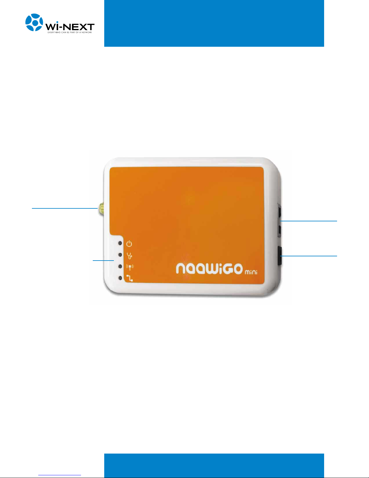
3. DESCRIPTION OF NAAWIGO MINI
3.3 Technical specification of Naawigo Mini
Features
Operating Mode
Access Point
Client
RootAP / Transparent Client
Repeater
Wireless Adapter
Wireless Routing Client
Gateway
Naaw mesh
WAN Type
Static IP
Dynamic IP
PPPoE
Device Management
Web Server
Telnet or Secure Shell (SSH)
Data Capture Notification
Event Logging (Syslog)
Detailed Statistics per Client
Certification
CE
Dimension and Weight
91,8 mm x 66 mm x 25 mm
Weight: 80 gr.
Hardware features
Linux OS
CPU Atheros AR2317/2318 - 180 Mhz
16Mb SDRAM - 4 Mb FLASH RAM
LAN Interface: 1x10/100Mbps
Virtual Access Point
Up to 4 SSIDs with unique MAC Addresses (BSSID)
802.1q VLAN tag per VAP with Bridging
Configurable Security (WEP,WPA,WPA2, MAC
Filtering) per VAP
Advanced Features
Build-in DHCP server + DNS forwarder
Transmission Power Control (One dB per step)
Closed System (suppress SSID)
Transmission Rate Control
Security
Station Isolation
MAC Filtering
64 / 128-bit WEP
802.1x authentication
WPA-EAP and WPA-PSK, WPA2
Led Indicators
Power, Diagnostic, LAN, WAN, WLAN
Power Requirements ( DC Supply )
9VDC (Can Range from 9V to 15V)
Integrated Antennas
2 dBi detachable SMA antenna
802.11b/g
Environment
Temperature: from -20°C to +70°C
Humidity: from 10% to 80%
Technical specification