Willys CJ-2A User manual

Your
Operation
and Care
Manual
Universal Jeep
Model CJ-2A

Foreword
IN YOUR possession is a motor vehicle that has been thoroughly tested and inspected. Like any other piece of machinery, to
maintain it in first class condition, you should lubricate it at the time prescribed ith the proper grade of oil and grease and
keep all orking parts and oil holes clean and free of dirt and grit. You should also periodically have it systematically
inspected at an Authorized Willys-Overland Service Station.
In the follo ing pages e have set forth the kno ledge every o ner should have of his vehicle, that he may kno to take the
best care of it and handle it in such a ay that he ill get maximum service. Information is also available covering external
adjustments and minor emergency repairs. Read and follo these instructions carefully; e are sure that you ill then enjoy
the satisfactory operation that you rightfully anticipate.
Should adjustment or repair seem necessary beyond your ability, don't experiment; have the ork done by a competent repair
man. It ill al ays prove best and cheapest in the end to have the ork done by the Dealer from hom you purchased your
car. Many Willys-Overland Dealers have factory trained mechanics and all are familiar ith the construction and adjustments
through the cooperation of the manufacturer.
Do not attempt any adjustments as long as the vehicle is operating satisfactorily.
Be sure to obtain the O ner Service Policy, provided by your Dealer on delivery of your ne vehicle.
Caution
Accept and use only Genuine Factory Parts
Imitation parts are usually of inferior quality and can do serious damage to other mechanical parts of your vehicle.
Genuine parts are sold by all authorized Willys-Overland Dealers. Be sure non other than genuine parts are placed in your
vehicle.
Presence of parts other than those furnished by Willys-Overland ill void the manufacturer's Warranty.
NOTE: Parts replaced under the terms of the Warranty must be left ith the Willys-Overland Dealer ho makes the
replacement, if full credit is expected.
This is important for O ners to kno , hen travelling outside the territory in hich their vehicle as originally purchased,
particularly hen credit for old parts cannot be established to the satisfaction of the Dealer.
In this connection, a for arding address should be given by the O ner in order to insure the credit reaching him.
Standard Warranty
THE only Warranty under hich ne Willys-Overland Motor Vehicles are sold is that of the Manufacturer, being the Standard
Warranty recommended by the Automobile Manufacturer's Association, and is as follo s:
"This is to certify that e, WILLYS-OVERLAND MOTORS, INC., TOLEDO, OHIO, U.S.A. arrant each ne
motor vehicle manufactured by us, to be free from defects in material and orkmanship under normal use and
service, our obligations under this Warranty being limited to making good at our factory any part or parts thereof,
including all equipment or trade accessories (except tires) supplied by the Car Manufacturer, hich shall, ithin
ninety (90) days after making delivery of such vehicle to the original purchaser or before such vehicle has been
driven 4000 miles, hichever event shall first occur, be returned to us ith transportation charges prepaid, and
hich our examination shall disclose to our satisfaction to have been thus defective; this arranty being
expressly in lieu of all other arranties expressed or implied and of all other obligations or liabilities on our part,
and e neither assume nor authorize any other person to assume for us any other liability in connection ith the
sale of our vehicles. This arranty shall not apply to any vehicle hich shall have been repaired or altered
outside of an Authorized Willys-Overland Service Station in any ay so as, in the judgment of the Manufacturer,
to affect its stability or reliability, nor hich has been subject to misuse, negligence or accident"
The Manufacturer makes no arranty against, nor assumes any liability for any defect in metal or other material in any part,
device or trade accessory hich cannot be discovered by ordinary factory inspection.
WILLYS-OVERLAND MOTORS, INC.
NOTE -- Willys-Overland Motors, Inc., reserves the right at any time or times to revise, modify, discontinue or change any
models of its vehicles, or any part or parts thereof, ithout notice; and, ithout it or the Seller, incurring any liability or
obligation to the Purchaser.

Jeep CJ2A Speci ications
on The CJ2A Page
Engine "Go-Devil" L-Head
Number of cylinders........................................4
Bore...............................................................3 1/8"
Stroke............................................................4 3/8"
Piston Displacement........................................134.2 cu. in.
Compression Ratio..........................................6.48 to 1
Horsepo er -- SAE........................................15.6
Horsepo er (actual @ 4,000 RPM)................60
Torque (max. @ 2,000 RPM).........................105 Lbs. Ft.
Dimensions and Capacities
Wheelbase......................................................80"
Tread..............................................................48 1/4"
Overall Width..................................................59"
Overall Height (Top up)...................................69 3/8"
Overall Height (Top do n)..............................52 3/8"
Overall Length.................................................122 3/4"
Road Clearance...............................................8 5/8"
Weight -- Maximum Payload............................800 lbs.
Shipping (Less ater, oil and fuel).....2,037 lbs.
Curb (Including ater, oil and fuel)....2,137 lbs.
Gross (Loaded)................................2,937 lbs.
Maximum Approved Dra Bar Pull
(Continuous Operation)................................1,200 lbs.
Fuel Tank Capacity...........................................10.5 gals.
Cooling System Capacity...................................11 qts.
Lamp Bulbs
Head Lamp (7 in. Sealed Beam Type)
Upper Beam.................................................45 atts
Lo er Beam................................................35 atts
Parking Lamp Bulb............................................3 CP-SC
Tail Lamp Bulb..................................................21-3 CP-DC
Instrument Lamp Bulb........................................3 CP-SC
Fuse (Thermal Type) -- On Light S itch............30 Amperes
Lubrication Capacities
Engine Crankcase -- oil filter empty (quarts)..5 US / 4 1/4 Imp.
Transmission and Transfer Case (pints)..........6 1/2 US / 5 1/2
Imp.
Differential - Front Axle (pints)......................2 1/2 US / 2 Imp.
Differential - Rear Axle (pints).......................2 3/4 US / 2 1/4
Imp.
Oil Bath Air Cleaners (pints)..........................1 1/4 US / 1 Imp.
Brake System Fluid (pints).............................3/4 US / 5/8 Imp.
Location of Serial Number: Plate on outside left frame side rail
at the front and on instrument panel.
Location of Engine Number: Stamped on ater pump boss.
4
79.37 mm.
111.12 mm.
2199.53 cc.
203.20 cm.
122.55 cm.
149.86 cm.
176.21 cm.
133.03 cm.
311.78 cm.
21.90 cm.
362.88 kg.
961.63 kg.
1006.99 kg.
1369.87 kg.
544.32 kg.
39.74 litres
10.41 litres
No. 63
No. 1158
No. 63
4.73 litres
3.7 litres
1.18 litres
1.30 litres
591.40 cc.
354.84 cc.
Lubrication Speci ications
Chassis Lubrication
Transmission and Transfer Case
Differentials -- Front and Rear
Steering Gear
Wheel Bearings
Universal Joints (Front Axle
Shaft)
Universal Joints (Propeller Shaft)
Po er Take-Off Housing
Air Cleaner
Governor
Engine
Type Lube.
Chassis Lube.
Mineral Gear Oil
Hypoid Oil
Steering Gear Lube.
Wheel Bearing Lube.
Universal Joint Lube.
Chassis Lube.
Mineral Gear Oil
Engine Oil
Engine Oil
Engine Oil
Winter
No. 0
SAE 80
SAE 90
SAE 140
No. 2
No. 0
No. 0
SAE 80
Same Grade as used in engine
See Belo
Summer
No. 1
SAE 90
SAE 90
SAE 140
No. 2
No. 1
No. 1
SAE 90
Same Grade as used in engine
See Belo

Above 90º F.................SAE 30
Not Lo er than 32º F...SAE 20 or 30
As Lo as +10º F........SAE 20 W
As Lo as -10º F.........SAE 10 W
To temperatures belo -10º F, use SAE 10 W plus 10%
kerosene
Valve and Ignition Timing
Inlet opens 9 degrees before top centre
Inlet closes 50 degrees after bottom centre
Exhaust opens 47 degrees before bottom centre
Exhaust closes 12 degrees after top centre
Spark Setting
Spark set top centre ith automatic spark controls at rest, hen
using lo octane fuel.
Firing Order
Tappet setting for valve timing
Number of fly heel teeth
Piston Measurements
From Top Centre
.039" (9.91 mm.)
3.772" (95.81 mm.)
3.799" (96.49 mm.)
.054" (0.14 mm.)
"IGN" 5º BTC
1-3-4-2
.020" (0.51 mm.)
97

CJ2A Operation and Care
Manual -- Inspections and Precautions
At assembly a restrictor is placed between the intake manifold and the carburetor to limit the road speed to approximately 42
mph. To protect the vehicle, leave the restrictor in position for the first 500 miles of road operation, or e uivalent in industrial
operation, after which remove and discard it.
It is an obligation of the Selling Dealer to carefully inspect and adjust your Universal Jeep before delivery. After your vehicle has been
operated 1000 miles, return it to your dealer for the 1000 Mile Inspection in accordance ith Factory Form, Ser. 3455. This inspection is free
ith the exception of engine oil and anti-freeze solution used.
1000 Mile Free Inspection
Check steering system and front heel alignment.
Check spring clip nuts and spring shackles.
Check rear axle for oil and leaks.
Adjust body bolts.
Test service and hand brakes -- inflate tires.
Check cooling system for leaks and anti-freeze and fan belt adjustment.
Adjust clutch pedal.
Check operation of transmission and transfer case -- Check for oil level and leaks.
Check battery, generator output, headlamps and horn.
Tighten universal joint companion flange bolts.
Check operation of ammeter, heat indicator, fuel and oil gauges.
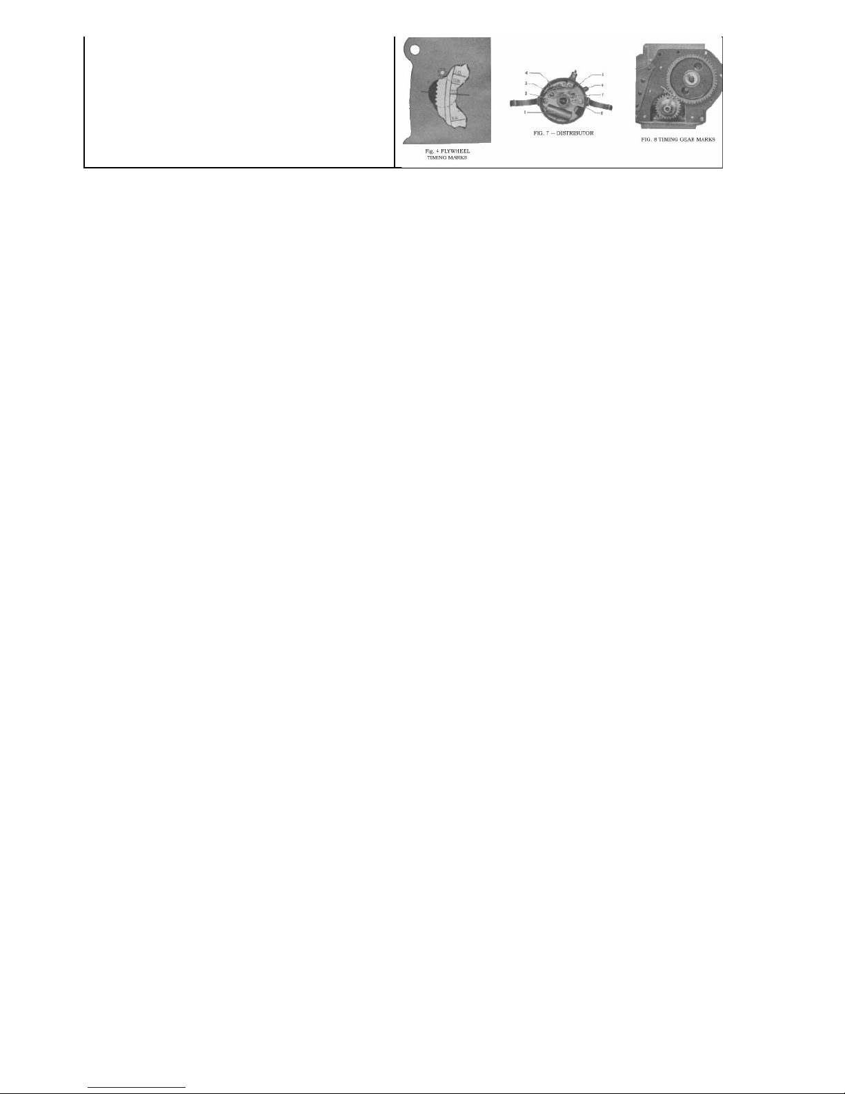
Tighten cylinder head nuts -- Check timing and distributor points.
Set spark plugs -- Adjust carburetor -- Check throttle controls.
Check engine for oil leaks -- Check fuel line connections.
Adjust valve tappets, if required.
Change engine oil (charge for oil) -- Lubricate vehicle.
Clean and refill air cleaner.
Clean fuel pump sump and strainer.
Check extra equipment attaching scre s -- Check for oil level and leaks.
FILL IN FOR YOUR REFERENCE
Vehicle Serial Number ____________________
Engine Serial Number ____________________
Purchase Date __________________________
Ignition Key Number _____________________
WILLYS-OVERLAND MOTORS, INC.
Proper Operation
DRIVING A NEW "JEEP"
Do not run your "Universal Jeep" faster than 40 miles an hour for the first 500 miles or if used on the farm or for industrial
operation, use care when pulling heavy loads in the lower gear ratios. If the vehicle is operated at high speeds while new or
used for heavy pulling for a long period, the closely fitted parts might possibly become overheated, resulting in scored pistons,
cylinders or burned bearings. During its entire life, never race the engine while making adjustments or when the vehicle is
standing idle. It the vehicle is not properly lubricated, our Warranty is null and void. Be sure to have your Willys-Overland
Dealer inspect your vehicle at the end of 1000 miles or e uivalent usage and every 2500 miles thereafter.
SPECIAL PRECAUTIONS
There are several points of difference bet een the Universal Jeep and a conventional vehicle to receive attention. As a general precaution
and for your information e are listing these "cautions" belo :
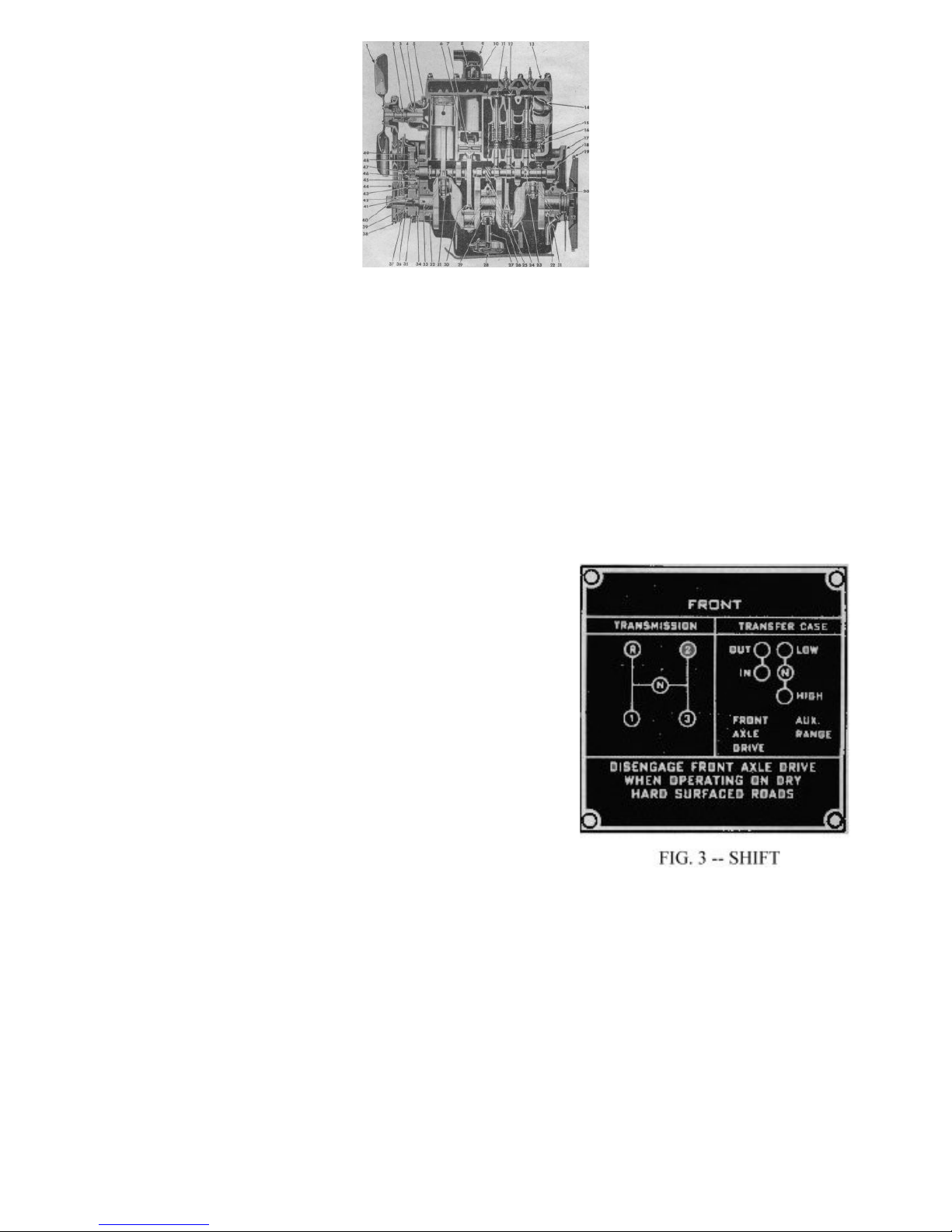
The Jeep is equipped ith a transfer case and four- heel drive to provide additional traction and a lo er gear ratio for use on difficult
terrain. Use the front heel drive only hen necessary. Consider the front heel drive and the transfer case as a lo er gear ratio than the
standard transmission lo gear and use it only hen greater po er is required.
The use of four- heel drive on hard surfaced high ays ill result in rapid tire ear and hard shifting of the transfer case, particularly hen
the front heels are steered even at a slight angle from the straight ahead position. If hard shifting occurs, disengage the clutch, start engine,
shift transmission into reverse gear, back the vehicle a fe feet, and disengage clutch. If transfer case is in lo range, shift into high then
shift front axle into "out" position (lever for ard).
T o drain cocks are provided to drain the cooling system. A drain cock is located under the left side of the radiator, ho ever, it is necessary
to drain the cylinder block separately. The cylinder block drain is located at the right front corner of the block directly under the generator.
Loosen the radiator cap to break the seal and permit complete draining.
Check the level of the lubricant often in the transmission and transfer case. Be sure the lubricant is at filler level in both units at all times.
As a standard, the clutch pedal is adjusted ith 1" free travel. As the clutch ears this becomes less. Be sure that there is free travel at all
times to prevent continuous operation of the clutch release bearing and rapid ear and slippage of the clutch. This adjustment is made by
lengthening or shortening the clutch control cable.
The ventilator valve, mounted in the intake manifold, must be free to operate. If it is stuck open very uneven engine operation at lo speed
ill result.
Be sure the exhaust manifold heat control valve is free at all times and the thermostatic control spring is above the stop.
Six scre s are used to attach the front heel brake backing plate and spindle to the spindle housing. These scre s are standard in dimensions
and thread pitch, ho ever, they are made of special steel and receive special heat treatment. Safety demands that only genuine factory scre s
be used at this point.

CJ2A Operation and Care
Manual -- Getting Started
FIG. 1 - VEHICLE CONTROLS
1. Windshield Wiper Arm
2. Windshield Wiper Blade
3. Windshield Centre Lock
4. Windshield Glass
5. Hand Wiper Handle and Knob
6. Windshield Tubular Frame
7. Windshield Frame and Glass Assembly
8. Windshield Inner Adjusting Arm
9. Windshield Outer Adjusting Arm
10. Adjusting Wing Scre
11. Top Bo Storage Retainer
12. Instrument Panel Light
13. Choke Control
14. Windshield Clamp
15. Ammeter
16. Hand Brake Handle
17. Ignition S itch
18. Starter S itch
19. Underdrive Shift Lever
20. Front Axle Drive Shift Lever
21. Transmission Shift Lever
22. Heat Indicator Gsuge
23. Accelerator Pedal
24. Speedometer
25. Brake Pedal
26. Clutch Pedal
27. Headlamp Dimmer S itch
28. Instrument Panel Light S itch
29. Oil Gauge
30. Main Lighting S itch
31. Fuel Gauge
32. Throttle Control
33. Rear Vision Mirror
34. Horn Button
35. Steering Wheel
36. Windshield Wiper Motor
TO MAKE VEHICLE READY.
•Fill the radiator ith clean, soft ater.
•Put gasoline in the tank.
•Fill the oil reservoir through the filler pipe at the right side of the engine until the oil indicator stick registers “FULL”.
(See “Lubrication Specifications”.)
•Supply all parts requiring lubrication ith oil or lubricant.
•See that the tires have proper pressure (See “Tire Pressure”.)
•Adjust the rear vie mirror to correct position for driver. If adequate vie is not obtainable, the mirror may be
adjusted by loosening the scre through the mounting bracket or by tilting in the ball and socket connection.
CONTROLS AND SWITCHES.
•The position of all controls and s itches is sho n in Fig. 1.
•The horn is operated by pressing the button located at the top center of the steering heel.
•The instrument panel light s itch is located along the lo er edge of the instrument panel to the left of the steering
post. The indshield iper control is mounted on the iper motor housing.
•The main light s itch No. 30 controlling both the head and tail lamps is conveniently located on the instrument panel
to the left of the steering post. It is of the plunger type – pull all the ay out for the “full on” position, half- ay for
“parking” and all the ay in is the “off” position.
•In addition to the main light s itch, the high and lo beams of the headlamps are controlled by a selector foot s itch,
located on the toe board to the left of the clutch pedal. Pressing and releasing the s itch button, ith the foot,
alternately changes the beam from high to lo and vice versa.
TO START ENGINE.
•Put the transmission gearshift lever No. 21, Fig. 1 in neutral. Place the transfer case lo and high shift lever No. 19 in
direct gear or in the rear position and disengage the front axle by placing the shift lever No. 29 in the for ard
position.
•Pull the choke control button No. 13 one-fourth of the ay out hich also opens the throttle slightly.
•Place the key in ignition lock No. 17 and turn it to the right, closing the ignition circuit.
•Disengage the clutch.
•Depress the foot starting s itch at No. 18.
•Should the engine fail to start at once, pull the choke all the ay out and press the starting s itch. When the engine
starts, push the choke in about one-third of the ay.
•Set the choke control at the best operating position and as the engine arms up, push the choke all the ay in. Do not
run ith the choke out as fuel is asted and the engine fouled.
•Should the engine fail to start, see the “Emergency Chart”.

FIG. 2 -- SIDE SECTIONAL VIEW OF ENGINE
1. Fan Assembly
2. Water Pump Bearing and Shaft
Assembly
3. Water Pump Seal Washer
4. Water Pump Seal Assembly
5. Water Pump Impeller
6. Piston
7. Wrist Pin
8. Thermostat Assembly
9. Water Outlet Elbo
10. Thermostat Retainer
11. Exhaust Valve
12. Intake Valve
13. Cylinder Head
14. Exhaust Manifold Assembly
15. Valve Spring
16. Valve Tappet Self-Locking
Adjusting Scre
17. Engine Plate -- Rear
18. Camshaft
19. Fly heel Ring Gear
20. Crankshaft Packing -- Rear End
21. Crankshaft Bearing Rear Drain
Pipe
22. Crankshaft Bearing -- Lo er
23. Valve Tappet
24. Crankshaft
25. Oil Pump and Distributor Drive
Gear
26. Connecting Rod Cap Bolt
27. Oil Float Support
28. Oil Float Assembly
29. Crankshaft Bearing Centre --
Lo er
30. Connecting Rod Assembly -- No.
2
31. Connecting Rod Bolt Nut Lock
32. Crankshaft Bearing -- Front
Lo er
33. Crankshaft Oil Passages
34. Crankshaft Thrust Washer
35. Crankshaft Gear
36. Crankshaft Gear Spacer
37. Timing Gear Cover Assembly
38. Fan and Generator Drive Belt
39. Crankshaft Oil Seal
40. Starting Crank Nut Assembly
41. Crankshaft Gear Key
42. Fan and Governor Drive Pulley
Key
43. Timing Gear Oil Jet
44. Fan, Generator and Governor
Drive Pulley
45. Camshaft Thrust Plate
46. Camshaft gear Retaining Washer
47. Camshaft Gear Retaining Scre
48. Camshaft Gear Thrust Plate
Retaining Scre
49. Camshaft Gear
TO START VEHICLE.
•Release hand brake, if set.
•Depress clutch pedal.
•Move transmission gearshift leer to first speed position – see Fig. 3
(Note that the front axle and transfer case shift levers are not used hen
the vehicle is driven on the high ay in rear heel drive.)
•Depress the foot accelerator pedal gradually and at the same time,
slo ly release the clutch pedal.
•Allo the vehicle to gain momentum (t o or three vehicle lengths), then
release the accelerator and depress the clutch at the same moment.
•Move the shift lever promptly to the second speed position.
•Depress the foot accelerator pedal gradually and at the same time,
slo ly release the clutch pedal.
•Shift to third or "high" speed in the same ay at approximately 18 to 20
mph, releasing the accelerator and depressing the clutch before moving
the shift lever.
•The synchronizing mechanism in the transmission makes gear shifting
silent and easy. This device adjusts the speeds of the t o gears to be
engaged and prevents "clashin
TO CHANGE TO LOWER SPEED.
•Depress the clutch pedal.
•Move the gearshift lever quickly to the next lo er speed, increasing the engine speed slightly, if traveling on level
road and release the clutch pedal.
•It ill be found advisable to make this change hen the engine is placed under heavy pull, or hen dropping do n to
a very lo speed, as hen travelling up a steep grade, in sand or in congested traffic.
•Never attempt to make the change ith the vehicle traveling at a high rate of speed.
TO STOP THE VEHICLE.
•Release the foot accelerator.
•Depress the clutch pedal and apply foot brake.
•When stopped, move gearshift lever into neutral.
•Set the hand brake and release the clutch and brake pedals.
TO REVERSE VEHICLE.
•With the vehicle at a standstill, depress the clutch pedal.

•Shift the lever into the reverse position, slo ly release the clutch pedal and regulate the car speed ith the foot
accelerator.
TO USE THE ENGINE AS A BRAKE.
The most effective brake for holding the vehicle back on a steep grade is the engine. To use the engine as a brake, shift into
one of the lo er speeds before starting to descend. Keep the clutch engaged, the throttle closed, and the ignition “ON”. Lo
gear ill hold any vehicle effectively on any hill it can climb.
Never engage the clutch suddenly hen the vehicle is coasting ith the clutch released and the transmission gears in mesh, as
damage to the driving mechanism may result.
FIG. 4 -- END SECTIONAL VIEW OF ENGINE
1. Ignition Distributor
2. Cylinder Head Gasket
3. Eshaust Valve Guide
4. Intake Manifold Assembly
5. Valve Spring Cover Assembly
6. Heat Control Valve
7. Crankcase Ventilator Baffle
8. Exhaust Manifold Assembly
9. Crankcase Ventilator Assembly
10. Distributor Shaft Friction Spring
11. Oil Pump Driven Gear
12. Oil Pump Gasket
13. Oil Pump Assembly
14. Oil Pump Pinion
15. Oil Pump Cover aft
16. Oil Pump Relief Plunger
17. Oil Pump Relief Plunger Spring
18. Oil Pump Relief Plunger
Shim
19. Oil Pump Relief Plunger
Spring Retainer
20. Oil Pump Sh21. Oil Pan
Assembly
22. Oil Pan Drain Plug
23. Oil Float Support
24. Crankshaft Bearing Do el
25. Crankshaft Bearing Cap to
Crankcase Scre
26. Oil Float Assembly
27. Oil Filler Tube
28. Oil Filler Cap and Level
Indicator
29. Distributor Oiler
STARTING VEHICLE ON UPGRADE.
In starting on an upgrade, hold the vehicle ith the hand brake, disengage the clutch and shift the transmission into lo speed,
then accelerate the engine ith the foot accelerator in the regular ay hile simultaneously releasing the hand brake and
engaging the clutch
SHIFTING GEAR IN TRANSFER CASE.
The transfer case is essentially a t o speed transmission, hich provides a lo and a direct gear and also a means of
connecting the engine po er to the front axle. It is an auxiliary unit attached to the rear of the standard transmission.
Control of the transfer case is through the t o shift levers, Fig. 1 No. 19 and No. 20. The left lever, No. 20, is used to connect
and disconnect the po er to the front axle. The right lever, No. 19 is used to shift the transfer case gears to secure either
“High” (direct drive) or a very lo gear ratio for heavy pulling requirements.
Instructions for shifting gears in the transfer case are as follo s: See Fig. 3.
1. To engage front axle drive, depress the clutch pedal, release accelerator and move the left hand shift lever (No. 20) to
rear position
2. With the front axle drive engaged, the right hand lever (No. 19) may be shifted to the rear into “High” (direct) or
for ard into “Lo ”. The “Neutral” position mid ay bet een “High” and “Lo ” is for use hen the po er take-off belt
drive is used. The vehicle cannot be driven hen this lever is in “Neutral”.
3. To disengage the front axle drive, depress the clutch pedal, release the accelerator and shift the left lever to the for ard
position. The transfer case can be operated only in “High” (direct drive) hen the front axle drive is disengaged.
4. Shifting from high to lo transfer case gear should not be attempted except hen the vehicle is practically at a
standstill. The front axle drive must be engaged for this shift. Release the accelerator and depress the clutch pedal – move
the left hand shift lever to the rear position to engage the front heel drive, then move the right hand shift lever to for ard
position (lo transfer case gear).
5. Shifting from lo to high transfer case gear may be accomplished at any time, regardless of vehicle speed. Release
accelerator and depress clutch pedal and shift right hand lever into rear position.
USE OF FOUR WHEEL DRIVE.
The “Universal Jeep” is equipped ith four- heel drive and transfer case to provide additional traction and a lo gear ratio for
use on difficult terrain and to provide lo speed pulling po er for industrial and agricultural use. Four- heel drive should be
used only hen greater traction and po er are required than provided by the standard transmission and lo gear.
Avoid the use of four- heel drive on hard surfaced high ays as it ill result in rapid tire ear and hard shifting of the transfer
case gears. Should hard shifting occur, disengage the clutch, start engine, shift the transmission into reverse gear, back the
vehicle a fe feet, and disengage the clutch. If transfer case is in lo range, shift into high, then disengage front axle drive (left
lever for ard).

STEERING KNUCKLE OIL SEAL.
When parking during cold, et eather, s ing the front heels from right to
left to ipe a ay moisture adhering to the front axle universal joint housings
and oil seals, Fig. 5. This ill prevent freezing ith resulting damage to the oil
seal felts. When the vehicle is stored for any period, the front axle universal
joint housings should be coated ith light grease to prevent rusting.
How to Save Gasoline
1. In cold eather economical starting of the engine is easily obtained by pressing do n on the accelerator pedal once or
t ice, then push do n on the clutch pedal and start engine using the choke sparingly. Do not use the choke hen starting a
arm engine.
2. Do not use the choke excessively hile engine is arming up and never leave it out longer than absolutely necessary.
3. Accelerate gently. Tramping on the accelerator pumps more gasoline into the cylenders than can be effectively used.
4. Holding the car in second gear until you get up to high speeds may easily double the gasoline you should use in getting
under ay. Shift into high gear at about 20 miles per hour.
5. Fast driving uses up more gasoline. Travel at moderate speeds if you ant gasoline economy.
6. Decelerate to a gradual stop. Sudden stops, like sudden starts, are asteful of gasoline.
7. Park your car in the shade if possible, hot sun evaporates gasoline.
8. Don't drive your tires ith less than the proper amount of air pressure. Under-inflated tires mean more road friction, more
ork for the engine to do -- and therefore more gasoline consumed. See "Tire Pressure".
9. Keep the battery charged up in good condition. It helps starting and provides good ignition thereby reducing loss of
gasoline.
10. Letting the engine idle for long periods astes gasoline.
11. Be sure that the carburetor is in proper condition for maximum mileage and po er.
12. One faulty or dirty spark plug may aste as much as 10 percent of your gasoline. Have the spark plugs tested
occasionally.
13. Keep your car ell lubricated at all times, and be very careful to follo the instructions on "Lubrication".
14. Keep the radiator filled to the proper level; your engine ill remain at a more constant temperature. An overheated engine
uses more gasoline.
15. Check the operation of the automatic heat control on the exhaust manifold. The purpose of this heater is to arm the
mixture of air and gasoline as it leaves the carburetor, in order to give better vaporization. (See Manifold Heat Control).
16. It is a good idea to have a complete engine tune-up every 5,000 miles, or at least t ice a year -- in the Fall hen preparing
for Winter driving and again in the Spring. The O ner Service Policy entitles you to an adjustment and complete
inspection ithout charge at the end of the first 1000 miles.

CJ2A Operation and Care
Manual -- General Lubrication
General Lubrication
The use of high grade lubricants and regular application is specially essential hen operating the “Jeep” because of the
diversified service it performs. The amount of trouble free service received ill be in proportion to the care given. Lubricate
the vehicle in accordance ith the type of service performed.
The follo ing pages should be referred to for instructions covering grade and quality of lubricant for all parts of the vehicle.
The mileage instructions should be follo ed hen the vehicle is used for road ork. It is impossible to give accurate hourly
instructions because of the diversified service and conditions under hich the vehicle may be operated. The hours indicated are
approximate. To obtain maximum service, good judgment must be used to lubricate the vehicle according to the type of ork
being done. As an example – hen used as a farm tractor under dusty conditions the chassis should be lubricated daily as the
ne lubrication forces grit and dirt, hich has accumulated during the day, from the bearing surfaces. Under these conditions,
the air cleaner should also be cleaned and refilled daily or under extreme conditions t ice daily.
Because of the importance of correct lubrication, detailed recommendations, unit capacities and specifications are given in the
follo ing paragraphs.
Lubrication Speci ications
Chassis Lubrication
Transmission and Transfer Case
Differentials -- Front and Rear
Steering Gear
Wheel Bearings
Universal Joints (Front Axle Shaft)
Universal Joints (Propeller Shaft)
Po er Take-Off Housing
Air Cleaner
Governor
Engine
Type Lube.
Chassis Lube.
Mineral Gear Oil
Hypoid Oil
Steering Gear Lube.
Wheel Bearing Lube.
Universal Joint Lube.
Chassis Lube.
Mineral Gear Oil
Engine Oil
Engine Oil
Engine Oil
Winter
No. 0
SAE 80
SAE 90
SAE 140
No. 2
No. 0
No. 0
SAE 80
Same Grade as used in engine
See Belo
Summer
No. 1
SAE 90
SAE 90
SAE 140
No. 2
No. 1
No. 1
SAE 90
Same Grade as used in engine
See Belo
Above 90º F.................SAE 30
Not Lo er than 32º F...SAE 20 or 30
As Lo as +10º F........SAE 20 W
As Lo as -10º F.........SAE 10 W
To temperatures belo -10º F, use SAE 10 W plus 10% kerosene.
ENGINE LUBRICATION.
Lubrication of the engine is accomplished by means of a force-feed continuous circulating system. This is effected by means of a gear type
pump, located externally on the left side of the engine, and driven by a spiral gear on the camshaft.
The oil is dra n into the circulating system through a floating oil intake. The floating intake does not permit ater or dirt to circulate, hich
may have accumulated in the bottom of the oil pan, because the oil is dra n horizontally from near the top surface.
An oil pressure gauge is mounted in the instrument panel, hich indicates the pressure being supplied to the circulating system. Failure of
the gauge to register may indicate absence of oil, leakage or a fault in the lubrication system and the engine should be stopped immediately.
If there is plenty of oil in the reservoir the mechanical fault must be corrected before starting the engine. Standard gauge reading is
approximately 35 at 30 miles per hour and 10 at idle speed.
The quantity of the oil in the crankcase is measured by the bayonet type oil level indicator hich is combined ith the oil filler cap located in
the oil filler pipe at the right side of the engine. When the oil level is belo the “Full” mark, pour sufficient ne oil into the reservoir to bring
the level to the “Full” mark.
When the vehicle leaves the factory the crankcase is filled to the correct level ith oil of the proper viscosity for the “break-in” period. When
the vehicle is used on the high ay, completely drain the engine oil at 500 miles and at 1000 miles, then every 2000 miles thereafter, by
removing the drain plug in the lo er left side of the oil pan. Replace the drain plug and refill ith 4 qts (5 qts. hen the engine oil filter has
been drained) of fresh oil. For heavy industrial or dusty field ork, change the oil at the first 10 hours, and each 50 hours thereafter. To
secure maximum engine life, atch the condition of the oil closely and should it become contaminated, due to conditions under hich the
vehicle has been operated, change it immediately.
Al ays drain the oil hen the engine is arm. The benefit of draining is, to a large extent, lost if the crankcase is drained hen the engine is
cold, as some of the foreign matter ill remain in the bottom of the oil pan.
At least once a year, preferably in the Spring, remove the oil pan and floating oil intake and ash thoroughly ith cleaning solution.
CHASSIS LUBRICATION.
When lubricating the chassis refer to the Lubrication Chart. For high ay travel, clean and lubricate points 2, 3, 4, 5, 6, 7, 8, 9, 10, and 11
each 1000 miles. When used in industrial or agricultural ork the period for lubrication depends entirely upon the type of ork being done.
When doing dusty field ork, lubricate these points daily as grit and dirt ill ork into the bearing surfaces and cause rapid ear unless
forced out by ne lubricant. The importance of using a good grade of chassis lubricant can not be exaggerated, for the cost ill be more than
repaid by longer ear and good service.
OIL FILTER.
The oil filter should be dismantled, cleaned and the filter element replaced at the end of the first 2000 miles of high ay travel, or 100 hours

of industrial or field use. Drain the filter at each oil change to prevent the old oil contained in the filter from mixing ith and contaminating
the ne oil. Replace the element at each 8000 miles of high ay use or 200 hours of industrial or field use.
AIR CLEANER.
Care of the air cleaner is EXTREMELY IMPORTANT – especially hen the vehicle is used under dusty conditions. Clean and refill the air
cleaner reservoir to the level mark, ith oil of the same grade used in the engine, at etch engine oil change. When the vehicle is used for field
ork, clean and change the oil in the cleaner DAILY and under dusty conditions TWICE DAILY. When cleaning, use a long scre driver or
other suitable tool to dislodge dirt sticking to the bottom and sides of the intake passage in the body of the cleaner.
STEERING GEAR.
Check the level of the lubricant in the steering gear housing every 1000 miles. Avoid the use of cup grease, graphite, hite lead or heavy
solidified oil. Remove the plug in the steering gear housing and use a hand gun to fill the housing slo ly.
WATER PUMP – CLUTCH.
The ater pump and clutch release bearings are prelubricated at assembly and the lubricant lasts for the life of the bearings.
GENERATOR.
T o oilers are provided, one at each end; three to five drops of engine oil is recommended every 1000 miles. Be sure to slip the commutator
end hole cover back in place.
STARTING MOTOR.
The oil hole cover on the commutator (front) end slips to one side; put three to five drops of engine oil in this hole every 1000 miles. Be sure
to slip cover back in place.
IGNITION DISTIBUTOR.
The oiler on the distributor should be lubricated every 1000 miles ith several drops of engine oil, Fig. 7, No. 6. Also place one drop of light
engine oil on the ick, No. 2 located in the top of the shaft, hich is accessible by removing the rotor arm and sparingly apply soft grease on
the breaker arm cam No. 4, and a drop of oil on the breaker arm pivot, No. 3. See PROPOER MAINTENANCE for Fig. 7.
SPEEDOMETER AND DRIVE.
Some of the speedometers supplied are equipped ith a ick type oiler located on the drive shaft boss directly above the tube and shaft
connection to the speedometer head. Lubricate this oiler ith a fe drops of light oil t ice each year. Remove the drive shaft from the tube
once each year, clean it thoroughly and lubricate ith a good quality light graphite grease.
UNIVERSAL JOINTS (PROPELLER SHAFT).
Every 1000 miles lubricate the propeller shaft universal joints and the slip joints ith a good quality lubricant. Lubricate daily for field ork.
UNIVERSAL JOINTS (FRONT AXLE SHAFT).
The front axle universal joints are enclosed in the steering knuckle housings, hich are filled ith lubricant so require no attention other than
checking each 1000 miles to be sure the housings are filled to plug level. Once each year or every 300 hours of field ork the axle shafts and
universal joint assemblies should be removed, thoroughly cleaned and the housings filled ith ne lubricant.
WHEEL BEARINGS.
Front heel bearings should be removed, thoroughly cleaned, checked and replaced t ice yearly or every 6000 miles. The rear heel
bearings are equipped ith hydraulic lubricators. Lubricate them sparingly to guard against surplus oil saturating the brake lining. An oil
relief hole at the top of housing, Fig. 32, No. 1, indicates hen the bearing is filled ith oil.
TRANMISSION AND TRANSFER CASE.
Drilled passages are provided bet een the transmission and transfer case housings for circulation of the lubricating oil to provide unit
lubrication of the t o assemblies. The oil level should be checked each 1000 miles or at each lubrication. Drain and refill at each 6000 miles
or 300 hours of field ork.
Note: The requirements o these housings are small or economy, there ore, it is very important that the lubrication be changed
every 300 hours when the vehicle is used or dusty ield work.
FRONT AND REAR DIFFERENTIALS.
The differential gears require extreme pressure lubricant, hich is suitable for hypoid gear type axles. The level of the lubricant in these units
should be checked every 1000 miles. Do not mix different types of hypoid lubricants. Drain and refill the housings each 6000 miles or t ice
yearly. Use a light engine or flushing oil to clean out the housings.
Note: Do not use water, steam, kerosene, or gasoline or lushing. I the oil is decomposed, dismantling is necessary.
GOVERNOR.
At each lubrication, check the oil level in the governor housing. Use oil of the same grade used in the engine to maintain the lubricant at filler
plug level. Drain and refill the housing at each 300 hours of operation.
POWER TAKE-OFF SHAFT AND PULLEY DRIVE HOUSINGS.
Check the lubricant level at each lubrication job, maintaining the lubricant at filler plug level. Should the po er take-off be used frequently,
change the lubricant each 300 hours.

CJ2A Operation and Care
Manual -- Proper Maintenance
NEVER RUN ENGINE IN CLOSED GARAGE
Due to the presence of carbon monoxide (a poisonous gas in the exhaust of the engine) never rub the engine for
any length of time while the vehicle is in a small closed garage. Opening the doors and windows will lessen the
danger considerably, but it is safest if adjustments are being made that re uire the operation of the engine, to
run the vehicle out-of-doors.
INSPECTION.
The old adage "An ounce of prevention is orth a pound of cure" as never more true than hen applied to any motor vehicle.
The importance of regular systematic inspection cannot be over-emphasized. Small and seemingly unimportant faults, if
neglected, may gro into expensive major repairs. Regular inspections and prompt correction of small faults ill go far to ard
holding do n maintenance expense, eliminating delays in productive operations and upholding the high standard of reliability
and performance built into your "Jeep" at the factory.
ENGINE TUNE-UP.
For best performance and dependability the engine should have a periodic tune-up t ice yearly, preferably in the Spring and
Fall.
•Remove the spark plugs, clean them thoroughly and space the electrodes to .030" (0.76 mm.) gap.
•Clean and tighten the battery cable terminals, the battery ground connection and the ground strap on the right side of
the engine at the front engine support (See Fig. 10).
•Remove the distributor cap and inspect the contact points. Adjust the points to .020" (0.51 mm.) gap. See Fig.7 No.5.
•Check the ignition timing.
•Check the valve tappet clearance. Adjust to .014" (0.356 mm.) clearance ith engine hot or cold.
•Clean the fuel pump filter screen and check fuel line connections.
•Remove ventilator valve Fig. 12 and clean.
•Start the engine and allo it to run until thoroughly arm then set the carburetor idle scre so the engine ill idle at
600 rpm. (vehicle speed of approximately 6 mph).
•Adjust the carburetor lo speed idle scre so that the engine ill idle smoothly.
NOTE: Should the engine fail to perform satisfactorily and the trouble is definitely traced to the carburetor, consult your
Willys-Overland Dealer. Carburetor service is specialized and should not be undertaken unless the unit is thoroughly
understood.
VALVE AND IGNITION TIMING
Inlet opens 9 degrees before top centre
Inlet closes 50 degrees after bottom centre
Exhaust opens 47 degrees before bottom centre
Exhaust closes 12 degrees after top centre
Spark Setting
Spark set top centre ith automatic spark controls at rest, hen using lo octane fuel.
Firing Order
Tappet setting for valve timing
Number of fly heel teeth
Piston Measurements rom Top Centre
039" (9.91 mm.)
3.772" (95.81 mm.)
3.799" (96.49 mm.)
.054" (0.14 mm.)
"IGN" 5º BTC
1-3-4-2
.020" (0.51 mm.)
97
CHECKING VALVE TIMING
To check the valve timing, adjust the inlet valve tappet No. 1 cylinder to .020" (0.51
mm.). Use care in making this adjustment that the measurement is accurate ith
feeler gauges and that the tappet is resting against the lo est surface of the camshaft
cam. Rotate the crankshaft clock ise until piston in No. 1 cylinder is ready for the
intake stroke. (Mark "I-O" -- intake open -- on the fly heel is in the centre of the
engine.) With the crankshaft in this position, valve timing is correct if No. 1 intake
valve tappet is jut tight against the end of the valve stem. After checking, adjust all
of the tappets .014" (0.356 mm.).
Should the timing be incorrect it is advisable to consult your Willys-Overland Dealer
IGNITION TIMING

1. Condenser
2. Lubricating Wick
3. Breaker Arm
Pivot
4. Breaker Cam
5. Distributor Points
6. Oiler
7. Adjustment Lock
Scre
8. Adjusting Scre
The breaker points should be cleaned and adjusted to .020"
(0.51 mm.) opening. Remove all of the spark plugs except
No. 1. Rotate the crankshaft until No. 1 piston is coming
up on the compression stroke hich can be determined by
the resistance in the cylinder. Remove the spark plug and
continue to turn the engine slo ly until the mark "IGN" on
the fly heel is in the centre of the timing hole at the right
rear. This places the piston in the correct position to set the
ignition
Loosen the distributor clamp and rotate the distributor assembly until the
distributor rotor arm points to No. 1 terminal in the distributor cap and the
distributor points just start to break. To advance the timing, turn the
distributor in a clock ise direction; to retard it, turn in a counter-clock ise
direction. Tighten the clamp scre firmly but do not overtighten it.
The engine firing order is 1-3-4-2.
After setting the timing, revolve the crankshaft t o complete turns, to make
sure all backlash is eliminated, and check the timing to the fly heel mark
"IGN".
Ignition timing must be accurately set to obtain the maximum efficiency of
the engine. Information above is given only to enable the operator to place
the vehicle back in service should trouble develop. At the first opportunity,
have your Willys-Overland Dealer check the setting ith a neon timing
lamp hich can also be used to check the automatic spark advance
operation, by accelerating the engine.

CJ2A Operation and Care
Manual -- Proper Maintenance
(part 2 -- Engine Fails to Start, Oil System)
ENGINE FAILS TO START
Should the engine suddenly stop or fail to start, check the cause as follo s. Also see Emergency Chart.
•Make sure there is gasoline getting to the carburetor (Note: Should the trouble be traced to the gasoline supply see
FUEL SYSTEM) and that the ignition s itch is “ON”.
•Check ignition circuit iring connections to be sure they are tight and clean.
•Check that the distributor breaker points are smooth, have a flat contact ith each other and are set to the proper gap
(.020”). If the points are rough, replace them or temporarily smooth them ith a breaker point file.
•Inspect the distributor cap and rotor for cracks, carbon runners or burned places. If they are found replace the part.
•See that the current is reaching the distributor breaker points. To make this test, turn on the ignition s itch, remove
the distributor cap and turn the engine until the breaker points are open, then holding one end of a piece of ire on the
breaker arm, strike the other end on a clean, unpainted surface of the engine. No flash indicates a poor or open
connection bet een the s itch and distributor or an open circuit in the coil. If the ire and connections leading to the
coil are in good condition, then an open primary in the coil is apparent and a ne coil ill be necessary.
If a flash occurs hen testing the primary, as outlined above, it indicates that the primary circuit is all right and the trouble is
else here so the secondary coil circuit should be tested as follo s:
To test the secondary coil circuit, remove the distributor cap and turn the engine until the breaker points are making contact.
Turn “ON” the ignition s itch and remove the high tension ire (center ire) from the distributor cap. Hold this ire about
one-eighth of an inch from a clean, unpainted surface of the engine, then open and close the breaker points ith the finger,
giving them a short, snappy break. A fat, flame-coloured spark indicates the coil is in good condition. No spark indicates the
secondary inding of the coil is open, hile a thin, stringy spark indicates an internally shorted coil or a loose or inoperative
condenser. Condenser trouble ill also be indicated by badly burned breaker points.
Should the test sho a thin, stringy spark, check the condenser first. Be sure that the mounting scre is tight and is making a
good ground connection to the distributor body and also that the connecting ire to the distributor points is not broken or the
connection loose. Should no trouble be found in the condenser mounting or connection, install a ne condenser hich ill
localize the difficulty in either the coil or the condenser. No repairs can be made to either the condenser or coil, it being
necessary to replace them if inoperative.
MANIFOLD HEAT CONTROL
The manifolding is designed to utilize the exhaust
gasses of the engine to provide a quick means of
heating the inlet manifold, thereby reducing the
length of time the choke must be used after starting
a cold engine and making the engine more flexible
during the arm up period. The heat control valve,
Fig. 9, hich controls the amount of exhaust gasses
by-passed around the intake manifold insures more
complete vaporization of the fuel. This control is
fully automatic.
1. Heat Control Valve Lever
Key
2. Heat Control Valve Lever
Clamp Bolt Nut
3. Heat Control Valve Shaft
4. Heat Control Valve Lever
Clamp Scre
5. Heat Control Valve Bi-Metal
Spring Washer
6. Heat Control Valve
Counter eight Lever
7. Heat Control Valve Bi-Metal
Spring
8. Heat Control Valve Bi-Metal
Spring Stop
The valve shaft should turn freely in the manifold at all times. Note that the thermoplastic spring, No. 7, should be assembled
above the metal stop, No. 8.

ENGINE MOUNTINGS
The rubber engine mountings, hich are attached to the frame side rail brackets and
to the support plate, prevent fore-and-aft motion of the engine, yet allo free
side ise and vertical oscillation hich neutralizes vibration at the source. Keep the
mountings tight. A loose engine may cause vibration, clutch chatter or high fuel level
in the carburetor.
The rubber surface of the mountings partially insulates the engine from the frame. To
assure a positive electrical connection bet een the engine and the frame, a ground
strap is provided at the right front engine support under the generator. See Fig. 10.
The t o attaching scre s must be kept tight and the connections clean. A loose or
poor connection may result in hard engine starting, lo charging rate of the
generator or sluggish operation of the starting motor.
OIL PUMP ASSEMBLY
The oil pump assembly is provided ith a pressure relief valve hich controls the maximum oil pressure at all speeds.
The standard controlled pressure is 35 lps. at 30 mph. and 10 lbs. at the idle speed of 600 rpm. as registered by the dash gauge.
Pressure may be adjusted by installing or removing shims bet een the relief plunger spring and the spring retainer. Add shims
to increase the pressure or remove to decrease.
1. Cover Scre
2. Cover
3. Cover Gasket
4. Outer Rotor
5. Shaft and Rotor
6. Body
7. Driven Gear
8. Gasket
9. Gear Retaining Pin
10. Relief Valve Retainer
11. Relief Valve Retainer
Gasket
12. Relief Valve Spring
13. Relief Valve Plunger
The oil pump drive shaft drives both the pump and
the distributor assembly. See Fig. 2. Should it be
necessary to remove the oil pump assembly, first
remove the distributor cap and carefully note the
position of the rotor to allo reinstallation ithout
disturbing the ignition timing. When the pump is
installed, use care that the driving key on the end of
the distributor shaft is correctly meshed ith the slot
on the end of the pump shaft. To make the
installation ithout disturbing the ignition timing, the
pump gear must be correctly meshed ith the
camshaft gear to allo mesh of the distributor driving
key and slot ith the distributor rotor in the original
position. Should it be necessary to reset the ignition
timing, refer to the previous page.
1. Fan Assembly
2. Water Pump Bearing and Shaft Assembly
3. Water Pump Seal Washer
4. Water Pump Seal Assembly
5. Water Pump Impeller
6. Piston
7. Wrist Pin
8. Thermostat Assembly
9. Water Outlet Elbo
10. Thermostat Retainer
11. Exhaust Valve
12. Intake Valve
13. Cylinder Head
14. Exhaust Manifold Assembly
15. Valve Spring
16. Valve Tappet Self-Locking Adjusting Scre
17. Engine Plate - Rear
18. Camshaft
19. Fly heel Ring Gear
20. Crankshaft Packing - Rear End
21. Crankshaft Bearing Rear Drain Pipe
22. Crankshaft Bearing Rear - Lo er
23. Valve Tappet
24. Crankshaft
25. Oil Pump and Distributor Drive Gear.
26. Connecting Rod Cap Bolt
27. Oil Float Support
28. Oil Float Assembly
29. Crankshaft Bearing Centre - Lo er
30. Connecting Rod Assembly - No. 2
31. Connecting Rod Bolt Nut Lock
32. Crankshaft Bearing - Lo er Front
33. Crankshaft Oil Passages
34. Crankshaft Thrust Washer
35. Crankshaft Gear
36. Crankshaft Gear Spacer
37. Timing Gear Cover Assembly
38. Fan and Generator Drive Belt
39. Crankshaft Oil Seal
40. Starting Crank Nut Assembly
41. Crankshaft Carrier Key
42. Fan and Governor Drive Pulley Key
43. Timing Gear Oil Jet
44. Fan, Generator and Governor Drive Pulley
45. Camshaft Thrust Plate
46. Camshaft Gear Retaining Washer
47. Camshaft Gear Retaining Scre
48. Camshaft Gear Thrust Plate Retaining Scre
49. Camshaft Gear

FLOATING OIL INTAKE
The floating oil intake (No. 28, Fig. 2) is attached to the
crankcase ith t o scre s. The construction of the float
and screen cause it to remain on top of the oil, preventing
the circulation of ater and dirt.
Once each year remove the float, screen and tube and clean
thoroughly ith a suitable cleaning fluid. When replacing,
place some sealer on the gasket here the tube bears
against the engine crankcase. A leak at this point ill
allo air to enter the oil suction line seriously affecting oil
pressure.
CRANKCASE VENTILATOR
The crankcase ventilating system provides thorough,
positive ventilation hich reduces to a minimum the
formation of sludge. In operation (see Fgi. 12) clean air
flo s from the air cleaner through the short connecting
tube to the oil filler tube and then through the crankcase
and valve compartment to the intake manifold. Any
vapours in the crankcase are carried into the manifold and
burned. Positive air circulation reduces oil temperatures
and the formation of moisture due to condensation. Air
flo is controlled at the manifold by the control valve.
Be sure there are no air leaks at the tube connection
bet een the air cleaner and oil filler tube, and that the oil
filler tube cap gasket is in good condition. Al ays keep the
cap locked securely in place.
When tuning the engine of grinding valves, remove the control valve and clean it thoroughly. If this valve is blocked ith
carbon, the ventilating system ill not operate and should the valve fail to seat, it ill be impossible to make the engine idle
satisfactorily.

CJ2A Operation and Care
Manual -- Proper Maintenance
(part 3 -- Engine Electricals,
Fuel and Cooling Systems.)
GENERATOR
The generator is a 35-ampere, t o-brush unit hich does not require adjustment to increase or decrease output. This is
accomplished by the regulator hich limits the current generated to that hich is required by the battery. The generator
charging rate, as sho n by the ammeter, ill be lo hen the battery is ell charged and correspondingly higher as charging
is required.
As a general rule it ill not pay an o ner, not equipped ith specialized test equipment, to undertake generator repairs. There
are some adjustments hich may be made ithout this equipment and hich are covered belo .
Should the generator stop charging, examine all connections in the charging line to be sure they are clean and tight. Also note
the condition of the commutator and brushes. If the commutator is dirty and discoloured, it can be cleaned by holding a piece
of No. 00 sand-paper against it ith the engine running at idle speed. Do not use emery or carborundum cloth.
The brushes must slide freely in their holders and should they be badly orn or oil soaked, they should be replaced. Excessive
arcing bet een the cummutator and brushes usually indicates incorrect seating of the brushes against the commutator or high
mica insulation bet een the commutator segments. Incorrect seating may be corrected by dra ing a piece of No. 00 sand-
paper around the commutator ith the sanded side against the brush. After sanding, blo the carbon dust and sand from the
generator.
Should the above attention fail to make the unit operate satisfactorily, consult your Willys-Overland Dealer.
VOLTAGE REGULATOR
The regulator must be adjusted ith great accuracy; hear as ell as voltage and amperage must be considered hen adjusting
it. Should trouble develop in the regulator either consult a Willys-Overland Dealer or install a ne one.
DISTRIBUTOR ASSEMBLY
The distributor delivers the spark to the right cylinder at the right time. The mechanical breaker, built into the distributor, opens
and closes the primary circuit at the exact time for ignition. See Fig. 7 on the first page of Proper Maintenance.
The distributor cap should be kept clean for efficient operation. It should be inspected periodically for cracks, carbon runners,
evidence of arcing and badly corroded high tension terminals. If any of these conditions exist, the cap should be replaced.
Inspect the distributor rotor for cracks or evidence of excessive burning at the end of the metal strip. After a rotor has had
normal use, the end of the metal strip ill become burned. If burning is found on top of the rotor, it indicates the rotor is too
short and should be replaced. Usually then this condition is found, the distributor cap segment ill be burned on the horizontal
face and the cap should also be replaced.
The distributor contact points should be kept clean and not burned or pitted. The contact gap should be set at .020" (0.51 mm.).
When making adjustments, be sure that the fibre block in the breaker arm rests on one of the high points of the cam. Adjust the
points by loosening the lock scre and turning the eccentric head scre . Recheck the gap after tightening the lock scre .
Should ne contact points be installed they should be aligned so as to make contact at the centre of the contact surfaces. Bend
the stationary contact bracket to secure correct alignment and then recheck the gap.
SPARK PLUGS
Keep spark plug porcelains clean. Dirty porcelains ill cause hard engine starting and poor operation especially in damp
eather.
The spark plug electrode gap should be set at .030" (0.76 mm.). Too ide gap ill cause misfiring, especially at high speeds
and hen operating ith open throttle, hile a small gap causes poor idling. Uniform gap setting assures smooth engine
operation.
It is recommended that spark plugs be replaced at intervals of each 10,000 miles of service for, because of erosion, the spark
loses intensity.
STARTING MOTOR
The starting motor requires little attention except regular lubrication. It is a standard three-bushing type motor ith right-hand
type Bendix spring.
It is not advisable to lubricate the Bendix drive shaft. In use dirt and dust ill cling to the Bendix shaft, if lubricated. In time
the shaft may become gummy, preventing engagement of the Bendix pinion ith the fly- heel ring gear, especially in cold
eather. Should the starting motor turn ithout turning the engine, remove the motor and ash the Bendix assembly
thoroughly ith cleaning solution.

FUEL SYSTEM
The fuel system consists of the fuel tank lines, fuel pump, carburetor
and air cleaner. The most important maintenance attention is to keep
the system clean and free of ater, also periodically inspect for leaks.
Should the vehicle be stored for an extended period, the fuel system
should be completely drained and the engine started and allo ed to run
until the carburetor is emptied. This ill avoid oxidation of the fuel,
resulting in the formation of gum in the units of the system.
Gum formation is similar to hard varnish and may cause trouble in the
fuel pump valves or the carburetor float valve may become stuck or the
filter screen blocked. Gum formation can be dissolved by acetone,
obtainable in most drug stores. In extreme cases, it ill be necessary to
disassemble and clean the fuel system, ho ever, often one pint of
acetone placed in the fuel tank ith about one gallon of gasoline ill
dissolve any deposits as it passes through the system ith the gasoline.
CARBURETOR
The Carter carburetor, Model W.O.-596S is a precision instrument
designed to deliver the proper fuel and air mixtures at all engine
speeds. Carburetor parts ear little; the chief cause of faulty carburetor
is blamed for poor engine performance hen the trouble is else here
(see EMERGENCY CARD). Do not disturb the carburetor until it is
proven that the trouble is not else here. Should it be determined that
the carburetor is at fault consult your Willys-Overland Dealer.
The carburetor is provided ith an external adjustment to secure
smooth engine idle. Fig. 14, No. 15. To set this adjustment, proceed
asa follo s:
Make sure that the choke is in a fully open position Close the idle
adjustment by turning it to the right or in against the seat; then open it
one and one-quarter turns. Start the engine and run it until operating
temperature is obtained, then turn the adjustment in or out slightly until
the engine fires evenly. Open the throttle for a fe seconds allo ing
the engine to clean the manifold. Recheck the adjustment, then set the
throttle stop scre at an idle speed of 600 tpm. or approximately 6
miles per hour in high gear.
1. Pump Operating
Lever Assembly
2. Choke Valve
Assembly
3. Choke Shaft and
Lever Assembly
4. Metering Rod
Spring
5. Nozzle
6. Nozzle, Retaining
Plug
7. Metering Rod Disc
8. Neddle, Pin, Spring
and Seat Assembly
9. Float and Lever
Assembly
10. Lo Speed Jet
Assembly
11. Idle Well Jet
12. Metering Rod Jet
and Gasket Assembly
13. Metering Rod
14. Nozzle Passage
Plug and Gasket
Assembly
15. Idle Adjustment
Scre
16. Idle Adjustment
Scre Spring
17. Idle Port Rivet
Spring
18. Throttle Valve
19. Pump Jet
20. Pump Jet Strainer
Nut
21. Pump Jet Strainer
22. Intake Ball Check
Assembly
23. Discharge Disc
Check Assembly
24. Pump Plunger
Spring
25. Pump Plunger and
Rod Assembly
26. Pump Arm Spring
27. Pump Connecting
Link
28. Pump Arm and
Collar Assembly
FIG. 14 CARBURETOR
FUEL DIFFUSER
The engine is equipped ith a fuel diffuser built as part of a thick insulting gasket hich is installed bet een the carburetor
and the intake manifold. In operation the diffuser causes intense s irling of the fuel and air in the manifold. Under some
operating conditions this results in a drier and more satisfactory fuel mixture.
FUEL PUMP
The fuel pump is of the diaphragm type attached to the left side of the crankcase and operated from an eccentric on the

camshaft, Fig. 13. The pump dra s gasoline from the fuel tank, through a filtering screen mounted in the pump sediment
chamber and forces it to the carburetor. The pump pressure is 4 ½ lbs. at 16” above the outlet at 1800 rpm. Engine speed.
The sediment chamber can be removed by backing off the thumbscre nut sufficiently to permit s inging the ire clamp to
one side. The bo l or cover should be ashed and iped dry and the screen dried and then cleaned ith a stiff brush. When
reassembling the bo l, make certain that the cork gasket is not broken; reverse it and position it flat on the seat then install the
bo l and tighten the thumb nut securely. After cleaning, start the engine and carefully inspect the bo l to guard against
leakage.
Lack of gasoline in the carburetor may be caused by the follo ing conditions:
•Gasoline tank empty.
•Leaking tubing or connections.
•Bent or kinked tubing.
•Clogged fuel lines – (or frozen).
•Sediment bo l on fuel pump loose.
•Dirty screen.
•Carburetor inlet valve stuck shut.
Should the carburetor flood (too much gasoline), check the unit to make certain that the needle valve Fig. 14, No. 8, is seating
properly and that the float No. 9 is not stuck.
CAUTION: Do not attempt repairs hich require disassembling of the fuel pump other than cleaning as special care is
required. It is recommended that all fuel pump trouble be taken up ith your Willys-Overland Dealer.
FUEL SUPPLY TANK
The capacity of the fuel tank is 10 ½ gal. (U.S.). When filling the tank, care should be used that no foreign matter or ater
enters the tank. Once each season, at a time hen the fuel supply is lo in the tank, remove the drain plug in the bottom to
drain out sediment and ater hich may have accumulated.
COOLING SYSTEM
The practice of checking the condition of the cooling system of you Jeep hile lubricating it ill guard against costly delays in
service. Inspecting the condition of the radiator and heater hoses; also the fan belt and ater pump ill eliminate the possibility
of an overheated engine due to a ater leak or loose fan belt.
RADIATOR ASSEMBLY
The radiator is designed to cool the ater under all operating conditions ho ever, the core must be kept free from corrosion
and scale and the air passages free of chaff, dust and mud.
At least t ice a year flush out the cooling system. A good ay to do this is to remove the drain cock at the bottom of the
radiator and that in the cylinder block under the generator. Place a hose in the radiator filler opening and adjust the flo of
ater to equal that draining from the t o openings. Start the engine and allo it to run until the cooling system is thoroughly
flushed. After flushing it is advisable to install a corrosion inhibitor in the system to prevent rust and scale. This may be
obtained from your Willys-Overland Dealer.
Should the air passages become clogged, do not use a metal tool of any kind to clean them. Use compressed air or ater
pressure and clean from the rear, forcing the dirt out through the front of the radiator.
RADIATOR FILLER CAP
The cap is of the pressure type, hich prevents evaporation and loss of cooling solution. A pressure up to 4 ½ pounds makes
the engine more efficient by permitting a slightly higher operating temperature. Vacuum in the radiator is relieved by a valve in
the cap hich opens at ½ to 1 pound vacuum.
DRAINING COOLING SYSTEM
To completely drain the cooling system, open both drain cocks; that at the bottom of the radiator and also in the cylinder block
under the generator. Remove the radiator cap to break any vacuum hich might prevent thorough draining.
THERMOSTAT
A 145º to 155º F. thermostat, Fig. 2, is used to provide quick arming and to prevent overcooling during normal vehicle
operation. The temperature at hich this unit operates is set by the Manufacturer and can not be altered. The thermostat should
be checked first, should sudden overheating occur, as failure to operate ill nearly block the ater circulation. As a check,
remove the thermostat and if the overheating is eliminated, install a ne one.
HEAT INDICATOR
The heat indicator is of the hydraulic type and is connected to a bulb mounted in the ater chamber of the cylinder head, by a
capillary tube. Should this unit fail to operate, it should be replaced as it is not practical to either repair or adjust it.

WATER PUMP
The ater pump assembly Fig. 15 is a centrifugal impeller type, of large capacity to circulate the
ater in the entire cooling system.
The sealed type double-ro ball bearing is integral ith the shaft and is packed at the time of
assembly ith a special high melting point grease, so requires no lubrication.
FAN BELT
The fan and generator are driven by a “V”-type belt. The drive is on the sides of the belt, therefore
it is not necessary to adjust it tight, hich might cause excessive ear on the ater pump and
generator bearings. Adjust the belt by s inging the generator a ay from the engine until the belt
can be depressed 1” by thumb pressure mid ay bet een the pulleys.
Table of contents
Other Willys Automobile manuals