Wintex Agro Wintex 2000 User manual

Vilhelmsborgvej 15 DK-7700 Thisted Tel.: (+45) 97990800 contact@wintexagro.com
Instruction Manual for Wintex 2000

2
2
Vilhelmsborgvej 15 DK-7700 Thisted Tel.: (+45) 97990800 contact@wintexagro.com
For your safety
Before starting the Wintex 2000 make sure that nobody is present within a range of 10
metres.
Be seated correctly on the ATV with one leg on each side of the seat and the hands placed
correctly on the handle bar.
When inspecting the Wintex 2000, you must always activate the emergency stop, and the
ATV must be turned off.
Every time you start the Wintex 2000, you must test the emergency stop. If the emergency
stop does not turn off the soil sampler, you must not use it.
Manufactured by: Wintex Agro ApS
Vilhelmsborgvej 15
DK-7700 Thisted
Type designation: Wintex 2000
Voltage: 12 volt DC
Year of production: 2013

3
3
Vilhelmsborgvej 15 DK-7700 Thisted Tel.: (+45) 97990800 contact@wintexagro.com
Start the ATV, and deactivate the emergency stop. The red button
must be up.
Activate the foot switch and the brake on the handle bar, and shortly
push the button at your right hand. Foot switch and brake lever must
be activated during the entire process. If one of them is released,
the process will stop.
Note: The emergency stop must always be activated at long stops,
else the battery will be discharged.
1. Starting the Wintex 2000
Program selector
Program 1 takes a soil sample from 0-60 cm. The depth can be
adjusted.
Program 2 takes soil samples from two different layers, from 0-30
cm and from 30-60 cm. The depth can be adjusted.
2. Selection of program
The lower sensor plate defines the depth in program 1 and in
program 2. Loosen the screws, and move the sensor plate up or
down to the desired depth.
3. Adjusting the depth
The upper sensor plate defines where the soil sample in program 2
will be divided. The depth can be adjusted from 0-30 cm. Loosen
the screws, and move the sensor plate to the depth where the soil
samples shall be divided.

4
4
Hydraulics
4. Interrupting the process
Due to various reasons it might be necessary to interrupt the
process. In this case just deactivate the foot switch, and the process
will stop immediately. When reactivating the foot switch and the
brake handle at the same time, the probe will go back into start
position. The soil will be discarded and not be filled into the soil
boxes.
Vilhelmsborgvej 15 DK-7700 Thisted Tel.: (+45) 97990800 contact@wintexagro.com
5. Replacement of O-ring for scraper
Set a new O-ring on the hub for the probe (see picture).
Remove the old o-ring by pulling it down.
Push the new O-ring up in place.

5
5
Vilhelmsborgvej 15 DK-7700 Thisted Tel.: (+45) 97990800 contact@wintexagro.com
Dismount the scraper. Then dismount the lower screws on each
side. Loosen the upper screws. Tilt the whole plate, and pull up
the probe.
6. Replacement of Probe
Dismount the sensors.
Dismount the three cheese-head screws with a 5 mm hex key.
Screw two of the cheese-head screws in again in order to be able
to dismount the revolving platform by pulling it down.
Use the special key which comes along with the Wintex 2000 to
loosen the probe from the oil hammer.

6
6
Vilhelmsborgvej 15 DK-7700 Thisted Tel.: (+45) 97990800 contact@wintexagro.com
Adjust the pressure by using a 2 mm hex key. Pressure will rise
when turning the key to the right. For lowering the pressure, the
key must be turned to the left. The pressure must be adjusted so
that the soil sampler stands firm and stable on the ground.
7. Adjusting the hydraulics
Adjusting the main pressure
Start the motor with max. RPM. Press the main valve. The
manometer must show 140 bar.
This valve is for adjusting the main pressure. The main pressure
is pre-set ex works on 140 bar. It must only be adjusted after
signing a written agreement with Wintex Agro ApS.
Fuse:
There is a 7.5 amp fuse for current control in the control box.
Dismount the plug.
Adjusting the pressure of the soil sampler towards the ground

7
7
Vilhelmsborgvej 15 DK-7700 Thisted Tel.: (+45) 97990800 contact@wintexagro.com
Loosen the lock nut. The rotation speed is adjusted by turning
the screw. When turning to the left, the probe will move faster.
When turning to the right, the probe will slow down. The
adjusting screw must be set to 50 r.p.m.
Press the button down, and turn it counter-clockwise. The
button will come up. Start the motor with max. r.p.m. Press
the main valve, and the probe will rotate.
Press the button down. Turn it to the left so that it stays down.
Loosen the lock nut. Adjust with a 6 mm hex key. Pressure
will rise when turning to the right. Lower the pressure by
turning to the left.
Adjusting the rotation speed
Adjusting the pressure of the probe
Depending on the vehicle’s weight and the kind of soil, the
pressure must be between 10 and 30 bar. Read the pressure
on this manometer, which only is for reading the pressure of
the probe.

8
8
688. Tightening and Adjustment of Chain
Loosen the bolt, and take it out. Then tighten the chain. Set the
bolt into an appropriate hole and, tighten the bolt.
10. Maintenance
IMPORTANT: After the first 8 hours of operation screws must be tightened.
Daily:
Lubricate the chain for rotation with oil.
Lubricate the chain for probe up/down with oil.
Check all chains tighten them if necessary.
Check and tighten vital parts.
Check the oil level of the hydraulics.
Check screws and nuts and tighten if necessary.
Vilhelmsborgvej 15 DK-7700 Thisted Tel.: (+45) 97990800 contact@wintexagro.com
699. Adjusting the sensors
The sensors for rotation must be adjusted so that they are right in
front of the contact points. Both sensors must be placed equally.

9
9
Vilhelmsborgvej 15 DK-7700 Thisted Tel.: (+45) 97990800 contact@wintexagro.com
9. Errors
Error
Causes
Remedying
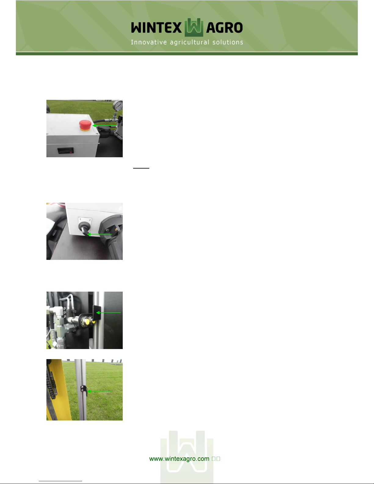
The Wintex 2000 does not start.
1) The fuse is blown.
2) The emergency stop is activated.
3) Does not activate all switches.
4) The switches are defect.
5) There is a lack of power supply.
1) Put in a new fuse.
2) Deactivate the emergency
stop.
3) See manual point 1.
4) Change the switches.
5) Charge the battery.
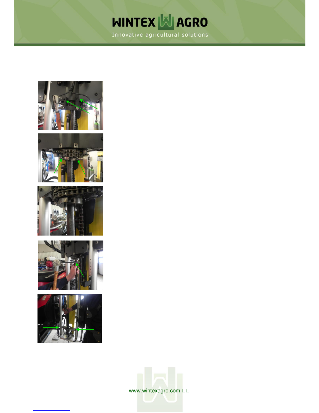
The probe does not rotate.
1) The sensors are not adjusted
correctly.
2) The chain is broken.
1) Adjust the sensors (see
manual point 8).
2) Replace the chain.
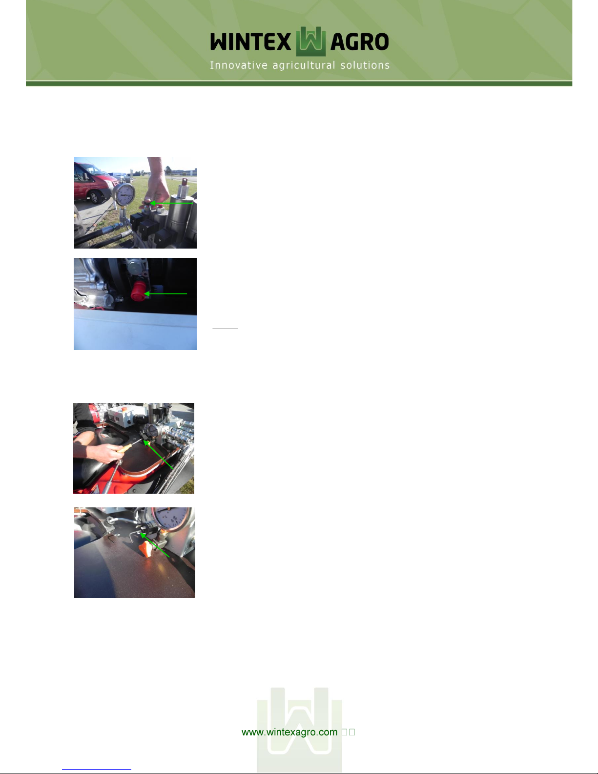
The soil cannot be squeezed out of
the probe.
1) The ejector tip is worn.
2) The probe is choked up with soil.
3) The probe is bent.
4) The O-ring is broken.
1) Change the ejector tip.
2) Clean the probe for soil.
3) Exchange the probe (see
manual point 5).
4) Replace the broken O-ring
with a new.
The ATV is being lifted when the
probe shall go into the ground.
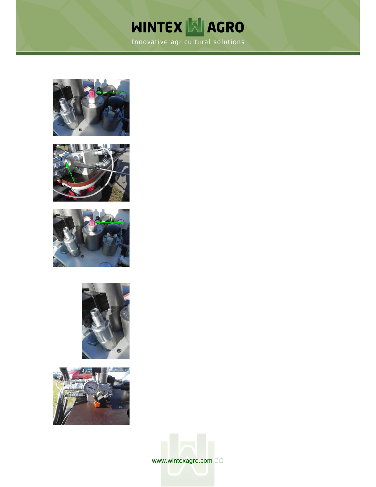
1) The pressure against the ground is
too high.
2) The pressure on the cylinder for
the probe is too high.
1) Reduce the oil pressure (see
manual point 6).
2) Reduce the oil pressure (see
manual point 6).
Table of contents