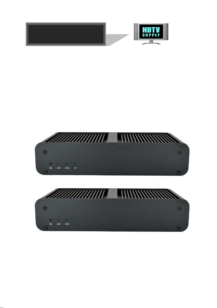
4K IP Streaming Extender
1
1. Product Introduction
The HDTVIPA100 is a network AV Transmitter/Receiver with HDMI and DP inputs up to
4K/60Hz/4:4:4, HDR. It is designed for HDMI/DP transmission over IP network with
external audio and control signals at distances up to 100m over copper cable. It works
with one control PC (Wake on LAN) and one 10GbE Switch to control a variety of
functions.
The HDTVIPA100 provides one of the most advanced IP Streaming solutions on the
market
utilizing AptoVision BlueRiver™ NT+ technology, which synergizes various IP/AV
standards to work together as one. It combines a variety of 4K IP technologies and
features under one unified protocol using a simplified topology.
The HDTVIPA100 features uncompressed video with zero-latency from transmitter to
receiver, seamless switching, Video wall, 1G Ethernet, IR, RS232, audio
embedding/de-embedding, audio down-mixing, etc. The control PC merge all functions
into Web-GUI, it means that user control system functions over multiple OS which
support browser anywhere in the same local area network.
Compares with traditional HDBaseT matrix AV Switching, HDTVIPA100 features low cost,
easy installation, more interoperability and flexibility. It is ideal for distributing AV over
10 Gigabit Ethernet in enterprises and other large-scale installations.
1.1 About 10G Network
Unlike traditional AV extension technology, such as HDBaseT, where transmitters and
receivers are connected point to point or joined together using custom matrix switches,
the IPA transmitter and receiver units are based on the inter compatible BlueRiver™
NT+ technology and connected using standard, off the shelf 10G Layer 2/3 network
switches.
This architecture makes use of data packages that can be easily and independently
routed to the desired unit. A variety of transmission modes is possible this way, from
one transmitter to one receiver (point to point) or one transmitter to many receivers
(point to multipoint) or many transmitters to many receivers (multipoint to multipoint)
with a software controllable video wall integration.
An added benefit of packet data transmission is that each signal type (video, audio,
RS232, etc.) is routed independently and not necessarily to the same destination. For
example, the HDMI video from a particular transmitter is routed to 4 receivers, while the
audio goes to all receivers in the setup.
This unlimitedly scalable and independent signal routing enables multiple, scalable
applications, including signal extension, splitting, switching, matrixing, and video wall
functionality.