Workrite SEHX54-72* Instruction manual

Workrite Ergonomics | 800.959.9675 www.workriteergo.com 1 of 12
Box1 Box2
Box4
Box3
Parts Included
Required & Sold Separately
QRear Bracket
Qty: 2
RConnector Bracket
Qty: 1
ALeg
Qty: 1 ALeg
Qty: 1
S#M6 × 12 mm Flat
Head Cap Screw
Qty: 8
Assembly & Installation Instructions:
Sierra 2-Leg Workcenter SEHX54–72*, SEHXL54-72
Styled or Flat Foot Kit
Standard or Programmable Switch
Worksurface
E4 mm Allen Wrench
Qty: 1
NLeg Cable, 1
meter
Qty: 2
OPower Cord
Qty: 1
KCable Spool
Qty: 2
M" Cable Loops
Qty: 10
BShort Bracket
Qty: 2 IControl Box
Qty: 1
HFoot Glide
Qty: 4
CLe End Bracket
Qty: 1
DRight End Bracket
Qty: 1
F#M6 × 14 mm Flat Head Cap
Screw
Qty: 20
L#8 × ⅝" Pan Head Screw
Qty: 12
G#12 × ¾" Pan Head Laminate
Top Screw
Qty: 38
J#12 × 2" Flat Head Screw
Qty: 2
P*Sierra Interface Kit Cable included
with HX models
Qty: 1

2 of 12 Workrite Ergonomics | 800.959.9675 www.workriteergo.com
IMPORTANT NOTE!
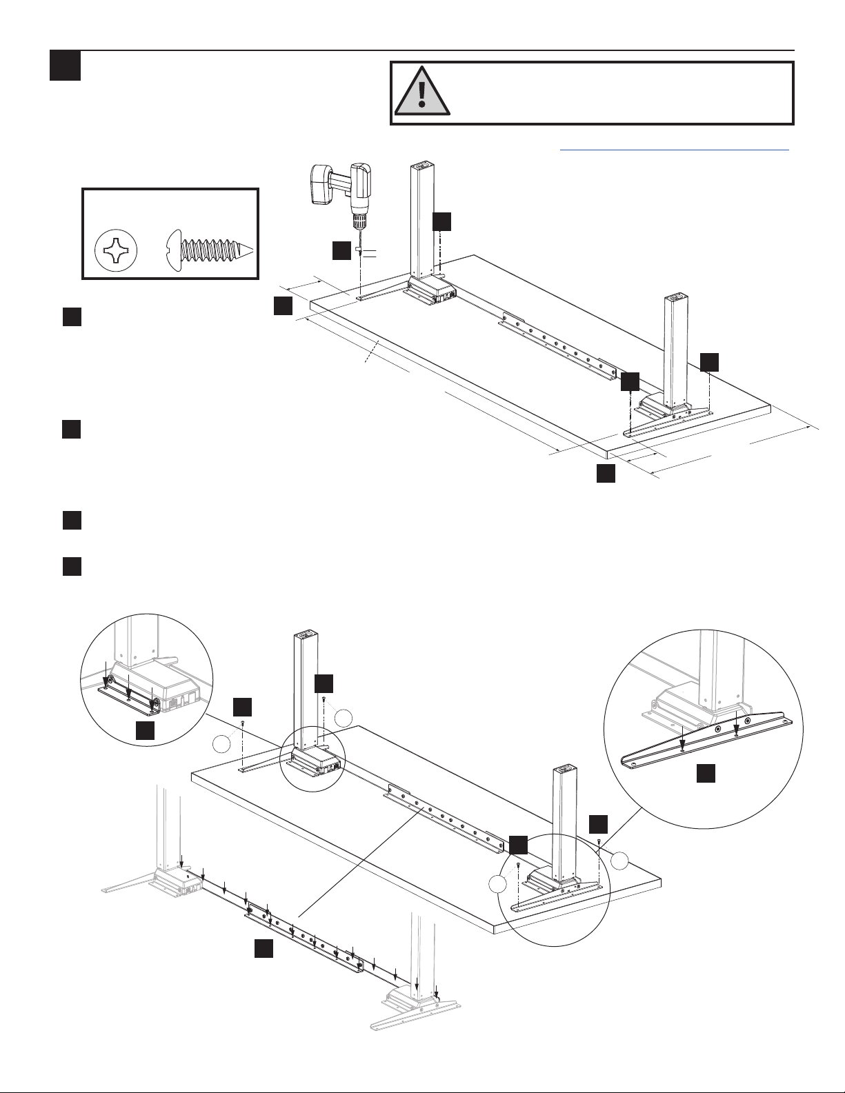
You must complete initialization (Step 12) at the end of
assembly or your workcenter WILL NOT FUNCTION PROPERLY.
WARNING: Maximum loading of table assembly is 225 lb. (102 kg.). Maximum load includes the weight of the
table top itself, any equipment placed upon it, and any equipment suspended or hanging under it. Loading should be evenly distributed
over table surfaces. “Payload Capacity” is the Workrite Ergonomics recommended maximum loading which includes the Workrite sourced
worksurface.
Sierra 2-Leg
V = 120 VAC, 60 Hz / 4.25 A maximum
IMPORTANT SAFETY INSTRUCTIONS:
When using an electrical furnishing, basic precautions should always be followed, including the following:
Read all instructions before using this Sierra Workcenter.
DANGER:To reduce the risk of electric shock, always unplug this Sierra Workcenter from the electrical outlet before
cleaning.
WARNING:To reduce the risk of burns, fire, electric shock, or injury to persons:
1. Unplug from outlet before putting on or taking o parts.
2. Close supervision is necessary when this furnishing is used by, or near children, invalids, or disabled persons.
3. Use this furnishing only for its intended use as described in these instructions. Do not use attachments not recommended by the
manufacturer.
4. Never operate this furnishing if it has a damaged cord or plug, if it is not working properly, if it has been dropped or damaged, or
dropped into water. Return the furnishing to a service center for examination and repair.
5. Keep the cord away from heated surfaces.
6. Do not use outdoors.
7. Do not operate where aerosol (spray) products are being used or where oxygen is being administered.
8. To disconnect, remove plug from outlet.
9. Each surface intended to support an equipment payload capacity of 225 pounds.
FOR COMMERCIAL USE ONLY
SAVE THESE INSTRUCTIONS
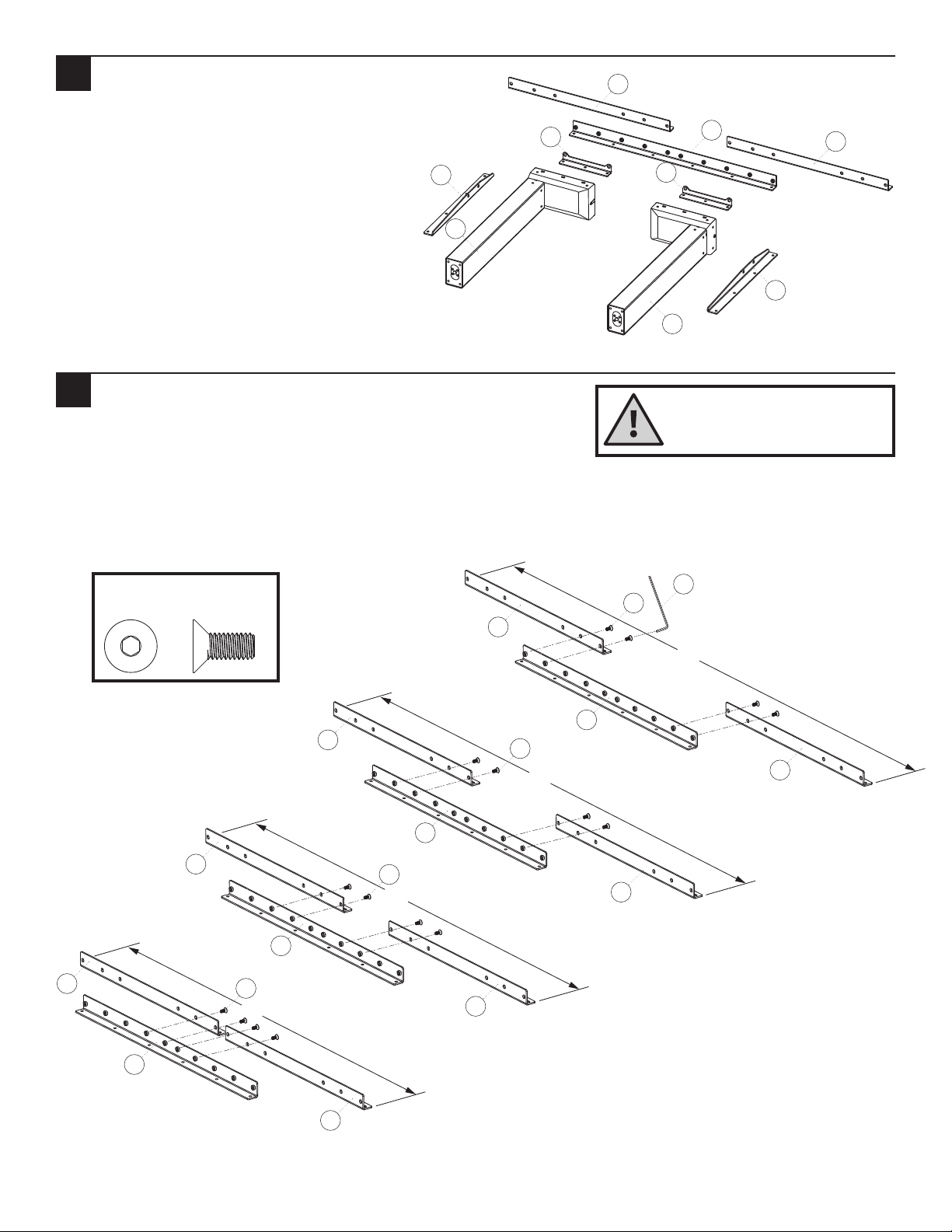
Verify that you have all the tools needed for the assembly
You will need the following tools:
#2 tip Phillips screwdriver or drill/driver
#3 tip Phillips screwdriver or drill/driver
M4 tip bit or 4 mm Allen Wrench (E)
If you do not have a Workrite worksurface, you will also need:
⅛" pilot drill bit
" pilot drill bit
or
✓

Workrite Ergonomics | 800.959.9675 www.workriteergo.com 3 of 12
Assemble Rear Brackets Set
Assemble Rear Brackets (Q) to Connector Bracket (R) using
#M6×12 mm Flat Head Cap Screws (S).
Use this guide to determine the correct holes for mounting
based on the width of your workcenter.
Tighten securely.
Layout Legs and Brackets
Lay out Legs (A) and Brackets (B, C, D, Q and R)
on the floor.
61"
55"
49"
43"
S
S
S
S
H
Q
Q
Q
Q
Q
Q
Q
Q
R
R
R
R
2
1
D
Q
Q
A
A
C
B
B
R
To avoid stripping the threads, always
insert and make the first few turns
of the screw BY HAND with an Allen
wrench (E), ensuring it is in straight.
52" Workcenters
58" Workcenters
64" Workcenters
70" Workcenters
S#M6 × 12 mm Flat Head
Cap Screw
Hardware at actual size
Note!
Only use the #M6 × 12 mm Flat
Head Cap Screw (S) for assembly.

4 of 12 Workrite Ergonomics | 800.959.9675 www.workriteergo.com
Attach Brackets to Legs
Attach Short Brackets (B) using #M6×14mm Flat Head Cap
Screws (F) to both legs.
Attach Le End Bracket (C) and Right End Bracket (D) to sides
of the Leg (A) using #M6 × 14 mm Flat Head Cap Screws (F).
Attach Rear Bracket Assembly to sides of the
Leg (A) using #M6 × 14 mm Flat Head Cap
Screws (F).
Note: The Right End Bracket
will be on your le and vice
versa when the assembly is
seen upside down.
Tighten securely.
B
B
D
C
F
F
F
F
F
F
To avoid stripping the threads, always
insert and make the first few turns
of the screw BY HAND with an Allen
wrench (E), ensuring it is in straight.
Le Leg
Right Leg
Right End Bracket
Le End Bracket
front
Rear Bracket Assembly
Q& R
a
a
a
b
c
c
b
b
3
A
A
E
F#M6 × 14 mm Flat Head
Cap Screw
Hardware at actual size
Caution!
Only use the #M6 × 14 mm Flat Head
Cap Screw (F) for assembly.

Workrite Ergonomics | 800.959.9675 www.workriteergo.com 5 of 12
Attach Base to Pre-Drilled Workrite Worksurface
Note: For 2-Leg Corner and 120° Worksurface Mounting Instructions, go to: www.workriteergo.com/instructions
If you have a non-Workrite worksurface, skip to Step 5
Position leg assembly to align mounting holes in brackets to pre-drilled holes in worksurface.
Attach at the four corner locations using #12 × ¾" Pan Head Laminate Top Screws (G). If you use an electric
screwdriver, be sure it is on the lowest torque setting to avoid stripping the holes in the top.
With frame set positioned and the four corner screws secure, attach frame
set using the remaining #12 × ¾" Pan Head Laminate Top Screws (G).
Skip to Step 6.
G
3 screws per
Short Bracket
2 screws per End Bracket
(2 installed in Step 4b)
16 screws per
Rear Bracket Assembly
a
front
b
bb
b
c
c
c
b
a
b
c
4
G#12 × ¾" Pan Head
Laminate Top Screw
Hardware at actual size

6 of 12 Workrite Ergonomics | 800.959.9675 www.workriteergo.com
Attach Base to Non-Workrite
Worksurface
Note: For 2-Leg Corner and 120° Worksurface Mounting Instructions, go to: www.workriteergo.com/instructions
Position Leg Assembly
centered le to right and
6.125" from the front of the
worksurface, making sure the
frame runs parallel with the
back edge of the worksurface.
Use a ⅛" drill bit to drill pilot holes at the four corner locations.
You may wish to mark your drill bit so you do not drill any more
than ¾" deep and damage tour worksurface top.
Do not drill all the way through worksurface!
Attach at the four corner locations using #12 × ¾" Pan Head Laminate Top Screws (G). If you use an electric
screwdriver, be sure it is on the lowest torque setting to avoid stripping the holes in the top.
With frame set positioned and the six corner screws secure, drill pilot holes first then attach the frame set using
the remaining #12 × ¾" Pan Head Laminate Top Screws (G).
>¾"
6.125"
6.125" 23"- 30"
Center
Parallel to edge
front
5
a
b
a
a
b
3 screws per
Short Bracket
2 screws per End Bracket
(2 installed in Step 5c)
16 screws per
Rear Bracket Assembly
c
c
c
c
c
d
d
d
b
b
b
Note: Avoid trip or tip hazards!
For uniquely shaped, non-rectangular worksurfaces, it is the
installers responsibility to position the worksurface to minimize
extended overhangs and position feet fully under the worksurface.
G#12 × ¾" Pan Head
Laminate Top Screw
Hardware at actual size
d
G
G
G
G

Workrite Ergonomics | 800.959.9675 www.workriteergo.com 7 of 12
Attach Feet (sold separately) & Install Foot Glides
Install feet using #M6×14mm Flat Head Screws(F) included with this
Frame Set.
Attach Foot Glide (H) to bottom of the Feet supplied in your Foot Kit.
Attach Switch
Install switch with two #8 × " Pan Head Screws (L).
Note: You may have purchased a Programmable Switch which
installs in the same manner.
Loop Power Cord through Strain Relief on Control Box
Loop the Power Cord (O) thought the strain relief
channel on the bottom of the Control Box (I) as
shown. Leave eight inches of slack to rout cord.
Plug Power Cord (O) into port AC on the Control
Box (I).
Lay the Control Box down in installation location
with cables in place.
Standard Switch
Programmable Switch
or
8"
8"
a
a
b
b
b
6
O
O
7
H
L
H
I
I
F
8
b
b
a
a
bottom
Flat Foot shown
Standard Switch shown
F#M6 × 14 mm Flat Head
Cap Screw
Hardware at actual size
Caution!
Only use the #M6 × 14 mm Flat Head
Cap Screw (F) for assembly.

8 of 12 Workrite Ergonomics | 800.959.9675 www.workriteergo.com
Attach Control Box & Cable Spools to Worksurface
Position Control Box (I).
If you have a Workrite worksurface:
Locate the two pilot holes for the Control Box and proceed to Step 9b.
If you do not have a Workrite worksurface:
Place Control Box (I) in position and use a pencil to mark pilot hole placement. Control Box should be placed
towards rear center of worksurface as shown. Remove Control Box and drill pilot holes where marked.
Do not drill all the way through worksurface!
With Control Box (I) positioned over pilot holes, attach with two #12 × 2" Flat Head Screws (J).
Attach Cable Spool (K) with the #12 × ¾" Pan Head Screw (G) to underside of worksurface. If you do not have a
Workrite worksurface, mount Cable Spools (K) in a convenient location between Legs and Control Box.
Lay out Leg Cables (N) to be sure they reach from the Legs (A) to the Control Box (I).
a
a
b
c
d
d
d
c
c
b
9
K
K
I
G
A
A
G
N
N
O
G#12 × ¾" Pan Head
Laminate Top Screw
J#12 × 2" Flat Head Screw
Hardware at actual size
JJ

Workrite Ergonomics | 800.959.9675 www.workriteergo.com 9 of 12
Attach Cable Loops and Route Cables
Connect both of the 1 meter Leg Cables (N) to both Legs (A).
Wind any remaining slack around Cable Spools (K) to keep cables out of the way while leaving enough slack to
just reach the Control Box (I).
Attach Cable Loops (M) to underside of worksurface using #8 × ⅝" Pan Head Screw (L) making sure to wrap the
Cable Loop around the cable prior to attaching. If you do not have a Workrite worksurface, attach cable loops in
convenient locations between Legs or Switch and the Control Box.
L#8 × ⅝" Pan Head
Screw
I
b
b
b
a
a
a
c
10
L
L
L
M
K
K
M
M
Hardware at actual size
N
N
N
A
A
c
c
c

10 of 12 Workrite Ergonomics | 800.959.9675 www.workriteergo.com
Connect Leg Cables, Switch Cable and Power Cord to Control Box
Connect the Leg Cables (N) to the ports “1” & “2” on both sides of the Control Box (I).
Insert the Switch Cable into port “A1” on the Control Box (I).
N
N
O
II
Right Leg Cable (P) into Port “1”
Switch Cable into Port “A1”
Power Cord (Q ) into Port “AC”
Left Leg Cable into Port "2"
b
a
b
a
a
11
N
N

Workrite Ergonomics | 800.959.9675 www.workriteergo.com 11 of 12
Put Workcenter Upright and Connect Power Cord to the Power Supply
Turn the workcenter over into an upright position.
Plug the Power Cord (O) into the power outlet.
Initialize Legs
Aer all Legs and the Switch are connected, and the power cord has been plugged in, hold the down arrow on
the Switch until the Legs make a short motion down and then back up. This initializes and synchronizes the
workcenter Legs.
Adjust Feet Glides
If necessary, adjust the Foot Glides (H) on workcenter feet to level the worksurface. Unscrew to increase height,
screw in to decrease height.
You must complete this
initialization step or your
workcenter will NOT
function properly.
Cleaning Instructions
To clean the Sierra legs, apply cleaner to a so cloth.
Suggested cleaners: Windex or Formula 409.
Do not use solvents and do not saturate or spray cleaners directly onto workcenter base.
Hold down the down arrow
until workcenter moves slightly
upwards!
✓
Parts & Accessories
Visit http://workriteergo.com/documentation/other/workrite_ergonomics_pricing_specification_guide.pdf for
replacement parts.
✓
Download and Install Sierra HX Interface Kit Soware
Visit http://workriteergo.com/support/sierra-interface/ to download
and install the Sierra Interface soware. You will also find an
installation guide for the Sierra Interface Kit Hardware (P) and a User
Guide to get the most out of the Interface Kit.
Sierra Interface Kit Cable (P)
O
a
b
12
13
14
b
a
15

12 of 12 Workrite Ergonomics | 800.959.9675 www.workriteergo.com
#1500273 Rev C
This manual suits for next models
1