WPG N10TAIR User manual

Rev 5.0/3-23 #351051
INTENDED FOR USE BY SKILLED
PROFESSIONALS • READ AND
UNDERSTAND BEFORE OPERATING
OPERATING
INSTRUCTIONS 908 W. Main • P.O. Box 368
Laurel, MT USA 59044
800-548-7341 (phone)
406-628-8231 (phone)
406-628-8354 (fax)
www.WPG.com
Record serial number in blank space above (to locate, see serial
label on the product).
HANDHELD
VACUUM CUP,
AIR-POWERED
Model numbers:
N10TAIR (shown at top-left),
N4950AIR (shown at bottom-right)
KEEP FOR FUTURE REFERENCE

#35105 Rev 5.0/3-232

Rev 5.0/3-23 #351051
SPECIFICATIONS .....................................................................................3
SAFETY...................................................................................................4
OPERATING FEATURES............................................................................5
ASSEMBLY..............................................................................................6
INTENDED USE .......................................................................................7
LOAD CHARACTERISTICS.................................................................................7
OPERATING ENVIRONMENT............................................................................8
DISPOSAL OF THE HAND CUP .........................................................................8
OPERATION............................................................................................9
BEFORE USING THE HAND CUP ......................................................................9
Taking Safety Precautions ...................................................................................................9
Performing Inspections and Tests .......................................................................................9
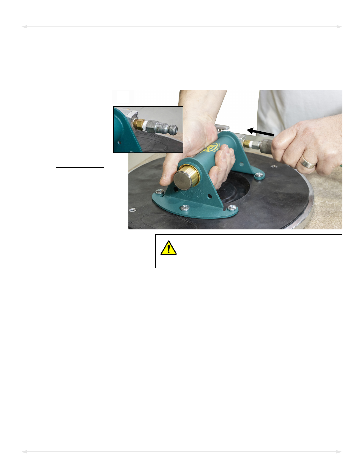
TOATTACH THE HAND CUP TO ALOAD ............................................................9
Positioning and Sealing the Pad on the Load......................................................................9
TOLIFT AND MOVE THE LOAD......................................................................11
Interpreting the Red-Line Vacuum Indicator.....................................................................11
Lifting the Load .................................................................................................................11
Monitoring the Red-Line Vacuum Indicator......................................................................11
In Case of Power Failure....................................................................................................12
TORELEASE THE HAND CUP FROM THE LOAD .................................................12
AFTER USING THE HAND CUP ......................................................................13
INSPECTIONS AND TESTS......................................................................14
INSPECTION SCHEDULE ................................................................................14
TESTING ...................................................................................................14
MAINTENANCE ....................................................................................15
VACUUM PAD MAINTENANCE.......................................................................15
Pad-to-Load Friction Coefficient .......................................................................................15
Pad Inspection ..................................................................................................................15
Pad Cleaning .....................................................................................................................16
TOREPLACE SEALING RING IN VPFS10T PADS ...............................................17
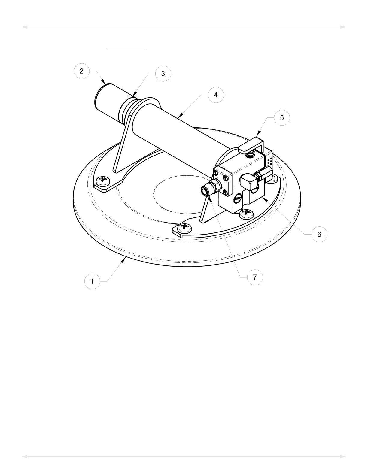
REPLACEMENT PARTS...........................................................................18
TABLE OF CONTENTS

#35105 Rev 5.0/3-232
WARRANTY AND REGISTRATION ..........................................................19
TOOBTAIN WARRANTY SERVICE OR REPAIR SERVICE ........................................19
Contact information..........................................................................................................19
TOREGISTER THIS WPG PRODUCT ...............................................................19
TABLE OF CONTENTS

Product
Description
Designed for use with a compressed air supply, these N-Series hand cups employ vacuum for attaching
to loads, which are manually lifted and carried, offering a wide range of handling options.
Model Number N4950AIR N10TAIR
Vacuum Pad1/
1...... Available with other rubber compounds for special purposes (see www.wpg.com).
Pad Spread
(standard rubber)
8" [20 cm] nominal diameter
(Model G0695)
10" [25 cm] nominal diameter
(Model VPFS10T2
2...... Standard with replaceable sealing rings for rough or textured surfaces (see “REPLACEMENT PARTS”).
)
Maximum Load
Capacity3
3...... The Maximum Load Capacity is rated at a vacuum of 17.5" Hg [-59.25 kPa] on clean, smooth, nonporous flat surfaces with a friction coefficient of 1. Pad
compound, load rigidity, strength, surface conditions, overhang, angle, center of gravity and temperature can also affect the lifting capacity. A “qualified
person” should evaluate the effective lifting capacity for each use (see definition under “Pad-to-Load Friction Coefficient”).
125 lbs [57 kg] 150 lbs [68 kg]
Hand Cup
Weight 3.33 lbs [1.51 kg] 6.26 lbs [2.84 kg]
Power
Source Compressed air, 70-80 psi [483-552 kPa] line pressure, 2 SCFM [57 liters/minute] @ 75 psi [517 kPa]
Operating
Elevation Up to 9,000' [2,743 m]
Operating
Temperatures 10° — 120° F [-12° — 49° C]
Service
Life 20,000 lifting cycles, when used and maintained as intended4
4...... Vacuum pad and other wear-out components are excluded.
Rev 5.0/3-23 #351053
SPECIFICATIONS

#35105 Rev 5.0/3-234
SAFETY
Wear personal protective
equipment that is appropriate for
the load material. Follow trade
association guidelines.
Do not attach the hand cup to
hoists or any other lifting device. It
is designed for manual use only.
Do not make any modifications to
the hand cup (see “LIMITED
WARRANTY”).
Use the hand cup only in an
approved “OPERATING ENVIRONMENT”
(see “INTENDED USE”).
Do not use a hand cup that is
damaged, malfunctioning, or
missing parts.
Do not use a hand cup if the sealing
edge of the vacuum pad is cut or
otherwise damaged.
Do not exceed the Maximum
Load Capacity or lift loads the
hand cup is not designed for
(see “INTENDED USE: LOAD CHARACTERISTICS”).
Do not use a hand cup to lift cracked
or broken glass.
Make sure the contact surfaces of
the load and vacuum pad are clean
before attaching the pad (see
“MAINTENANCE: VACUUM PAD
MAINTENANCE”).
Position the vacuum pad correctly
on the load before lifting (see
“OPERATION: TOATTACH THE HAND CUP
TO THE LOAD”).
Do not lift a load when the red-line
vacuum indicator is visible.
Do not touch the vacuum release
button during a lift.
Do not use the hand cup to support
a person.
Position yourself and other to avoid
injury in case of an unintended load
release.

Rev 5.0/3-23 #351055
Features shown here are underlined on their first appearance in each section following.
1 VACUUM PAD
2 PLUNGER
3 RED-LINE VACUUM INDICATOR
4 HANDLE
5 VACUUM RELEASE BUTTON
6 VACUUM PUMP (VENTURI)
7 1/8” NPT MALE FITTING
Note: A standard N4950AIR handheld vacuum cup is shown. Although some of the following
photos do not show this specific hand cup, they all illustrate how this kind of hand cup functions.
For information about specific parts, see “REPLACEMENT PARTS”.
OPERATING FEATURES

#35105 Rev 5.0/3-236
ASSEMBLY
1) Remove the handheld vacuum cup (hand cup) from its carrying case or remove the pad
cover, depending on the model. Save the case or cover for future use.
2) Connect the hand cup to an appropriate compressed air supply (see Power Source under
“SPECIFICATIONS”):
2A
Use appropriate
hose and/or fittings
to connect an air
line from the
compressed air
supply to the 1/8"
NPT male fitting on
the vacuum pump
(fig. 2A and inset).
Any damage or obstruction in air line would
result in unintentional load release and
possible injury.
Make sure the air line is routed
so that it does not become
tangled, damaged or obstructed
during operation.
Note: Disconnect the compressed air line when the hand cup is not in use. Otherwise, the
air compressor with cycle frequently.
3) Adjust the air pressure regulator to supply 70 psi [483 kPa]. Exceeding this pressure
consumes more air and does not improve hand cup performance. Pressures greater than
80 psi [552 kPa] should be avoided.
4) Perform tests as required under “TESTING”.

Rev 5.0/3-23 #351057
INTENDED USE
LOAD CHARACTERISTICS
Do NOT lift explosives, radioactive
substances or other hazardous materials.
Make sure the hand cup is intended to
handle each load according to these
requirements:
• The load weight must not exceed the Maximum Load Capacity.
• The load must be a single piece of relatively nonporous material with a flat and
relatively smooth contact surface.1To determine whether the load is too porous or
rough, attach the hand cup to the contact surface (see “TOATTACH THE HAND CUP TO A
LOAD”) and determine whether the red-line vacuum indicator would remain hidden
during a lift (see “Interpreting the Red-Line Vacuum Indicator”). If not, the load is not
compatible with this hand cup.
• The load's contact surface must be able to obtain a friction coefficient of 1 with the hand
cup’s vacuum pad (see “Pad-to-Load Friction Coefficient”). Otherwise, the capacity
should be derated appropriately.
• The load's surface temperature must not exceed the Operating Temperatures.2
• The load's maximum length and width are determined by its allowable overhang.3
• Although load thickness is not restricted, it may affect the angle of load orientation
and the amount of operator effort required for handling loads.
Note: Standard vacuum pads can stain or deform load surfaces with light colors or soft
coatings. Test such surfaces for damaging effects before using the hand cup on them.4
1..... Although concave vacuum pads can also attach to some curved loads, curvature can reduce lifting capacity. Contact WPG for more information.
2..... Vacuum pads made from a heat-resistant rubber compound can enable you to lift loads with higher surface temperatures. Contact WPG or an
authorized dealer for more information.
3..... The allowable overhang is the amount of load material that can extend sideways beyond the vacuum pad without breaking or otherwise being
damaged. This depends on the load material, its thickness, and the angle of handling (if any). Since every material has different physical
properties, the allowable overhang must be evaluated separately for each load type. Contact WPG or an authorized dealer for more
information.
4..... Alternative rubber compounds are available for these purposes. Contact WPG or an authorized dealer for more information.

#35105 Rev 5.0/3-238
OPERATING ENVIRONMENT
Make sure the hand cup is intended for use in each work environment, given the following
restrictions:
•
Never use hand cup in
dangerous environments.
This hand cup is not intended for any environment
that is dangerous to the operator or damaging to
the hand cup. Avoid environments containing
explosives, caustic chemicals and other dangerous substances.
• The work environment is limited by the Operating Elevation and Operating
Temperatures.
• The hand cup is not designed to be watertight.
Moisture can result in
reduced lifting capacity.
Do
not use it in rain or other unsuitable conditions.
DISPOSAL OF THE HAND CUP
After the Service Life of the hand cup has ended (see “SPECIFICATIONS”), dispose of it in
compliance with all local codes and applicable regulatory standards.
INTENDED USE

Rev 5.0/3-23 #351059
OPERATION
BEFORE USING THE HAND CUP
Determine whether the hand cup is capable of each intended task (see “SPECIFICATIONS” and
“INTENDED USE”). Then complete the following preparations:
Taking Safety Precautions
•
Read all directions and safety
rules before using hand cup.
Always wear appropriate
personal protective equipment.
Be trained in all relevant industry and
regulatory standards in your region.
• Follow trade association guidelines about
precautions needed for each load material.
Performing Inspections and Tests
Follow the “INSPECTION SCHEDULE”and “TESTING”.
TOATTACH THE HAND CUP TO ALOAD
Do not allow anything to interfere with free movement
of plunger when operating hand cup.
The hand cup is designed for its vacuum pump to run continuously.
Caution: Any interruption of airflow during operation could cause a pad release and personal
injury (see ).
Positioning and Sealing the Pad on the Load
1)
1A
Make sure the contact surfaces of the load and
vacuum pad are clean (fig. 1A —see “Pad
Cleaning”).

#35105 Rev 5.0/3-2310
2)
2A
Center the hand cup on
the load (fig. 2A). Make
sure the entire sealing
edge of the vacuum pad is
in contact with the load.
3)
3A
Press the hand cup
against the load until the
vacuum pad seals against
the contact surface.1As
the pad seals, the plunger
should automatically
retract into the handle,
hiding the red-line
vacuum indicator (fig.
3A).
Do not allow
anything to
interfere with free
movement of plunger
while vacuum pad is
attached.
1..... Although the vacuum pad may have become distorted during shipping or storage, this condition should correct itself with continued use.
OPERATION

Rev 5.0/3-23 #3510511
TOLIFT AND MOVE THE LOAD
Interpreting the Red-Line Vacuum Indicator
1A
A red line on a plunger serves as a vacuum indicator. When the red-line
vacuum indicator (arrow in fig. 1A) is hidden, vacuum is sufficient for lifting.
Never lift load when red-line indicator is visible, because this
action could result in load release and personal injury.
If air leaks back into the hand cup, the red line will become visible, to signal
the reduction in vacuum.
Lifting the Load
Always position yourself and others so as to avoid injury
in the event of unintentional load release.
1B
When the hand cup is ready, grasp the handle and use
correct lifting technique to raise the load as needed to
clear any obstacles while you are moving the load (fig.
1B).
Monitoring the Red-Line Vacuum Indicator
Monitor red-line vacuum indicator throughout
lift.
The plunger must remain completely
visible to the operator throughout
the entire lift.
Set load down immediately if red-line
vacuum indicator becomes visible.
Check the red-line indicator frequently, to
make sure the vacuum pad remains securely
attached. If the red-line indicator becomes
visible, immediately lower the load to the ground or a stable support.
Stop using the hand cup until the cause of the vacuum loss is identified (see “INSPECTIONS AND
TESTS” and “MAINTENANCE”). Correct any deficiency before resuming normal operation of the
hand cup.
OPERATION

#35105 Rev 5.0/3-2312
In Case of Power Failure
Set load down
immediately
if power failure
occurs.
A power failure at the compressed air supply could result in a load
release and personal injury, unless action is taken immediately: Lower
the load immediately to the ground or a stable support, and
discontinue hand cup use until power is restored.
TORELEASE THE HAND CUP FROM THE LOAD
Make sure load is supported independently
before releasing vacuum pad.
1) Use correct lifting technique to lower the load to the ground or a stable support.
2)
2A
3A
When the load is at rest and fully
supported, push the vacuum release
button (fig. 2A) until the vacuum pad
disengages completely from the
load.
3) Move the pad well away from the
load (fig. 3A) while continuing to
hold the button; otherwise, the hand
cup could reattach to the load.
OPERATION

Rev 5.0/3-23 #3510513
1A
1B
Use the carrying case (fig. 1A) or pad cover (fig. 1B) when
storing the hand cup or transporting it toanother location.
OPERATION
AFTER USING THE HAND CUP
Disconnect the hand cup from the compressed air line (see “ASSEMBLY”) or turn off the
compressed air supply, as appropriate.
Caution: Do not set the hand cup against any surface that could soil or damage the vacuum
pad.

#35105 Rev 5.0/3-2314
INSPECTIONS AND TESTS
INSPECTION SCHEDULE
Perform inspections according to the following frequency schedule. If any fault is found, correct
it and perform the next most frequent inspection before using the hand cup.
Examine vacuum pad for contaminates or damage (see
“Pad Inspection”).
Examine load surface for contaminants or debris.
Examine the vacuum pad, red-line vacuum indicator and
other features for visual damage (see “OPERATING
FEATURES”).
Examine hand cup’s structure for visual damage.
Examine the air supply system (including fittings and
hoses) for visual damage (see “ASSEMBLY”).
Check for unusual vibrations or noises while operating
hand cup.
• looseness, excessive wear or excessive corrosion
• deformation, cracks, dents to structural or functional
components
• any other hazardous conditions
Note: If a hand cup is used less than 1 day in a 2-week period, perform the Periodic Inspection
before using it.
TESTING
In addition to determining hand cup/load compatibility (see “LOAD CHARACTERISTICS”), test all
features and functions of the hand cup (see and ) before placing it in service initially, following
any repair, or whenever necessary.
Action Every Lift Frequent1
(every 20-40 hrs)
1...... The Frequent Inspection is also required whenever the hand cup has been out of service for 1 month or more.
Periodic2
(every 250-400 hrs)
2...... The Periodic Inspection is also required whenever the hand cup has been out of service for 1 year or more. Keep a written record of all Periodic Inspections.
If necessary, return the hand cup to WPG or an authorized dealer for repair (see “WARRANTY AND REGISTRATION”).
Examine entire hand cup for evidence of:

Rev 5.0/3-23 #3510515
MAINTENANCE
VACUUM PAD MAINTENANCE
Pad-to-Load Friction Coefficient
The friction coefficient represents the hand cup's ability to resist load slippage. The
Maximum Load Capacity is based on a friction coefficient of 1, as determined by testing of
a clean, new, standard rubber vacuum pad on clean, dry, regular glass. If the hand cup is used
under any other conditions, a qualified person must first determine the effective lifting
capacity.1
Long-term exposure to heat, chemicals or UV light can damage the vacuum pad. Replace the
pad and sealing ring (if applicable) every 2 years or more often when necessary.
Pad Inspection
1A
Inspect the vacuum pad (fig. 1A) according to the
“INSPECTION SCHEDULE”and correct the following faults
before using the hand cup (see “REPLACEMENT
PARTS”, when applicable):
• Contaminates on the face (item 1 in fig. 1A) or
sealing edge (item 2 in fig. 1A).
• Filter screen (item 3 in fig. 1A) missing from
face.
Replace pad if it has damaged
sealing edge.
• Nicks, cuts, deformation or abrasions in sealing edge.2
• Wear, stiffness or glaze.
1..... A “qualified person” has successfully demonstrated the ability to solve problems relating to the subject matter and work, either by possessing a
recognized degree in an applicable field or a certificate of professional standing, or by possessing extensive knowledge, training and experience
2..... If the hand cup has a VPFS10T pad, the replaceable sealing ring is the sealing edge.

#35105 Rev 5.0/3-2316
Pad Cleaning
1)
1A
Regularly clean the face of the vacuum pad
(fig. 1A), using soapy water or other mild
cleansers to remove oil, dust and other
contaminates.
Never use harsh chemicals on
vacuum pad.
Solvents, petroleum-based products (including
kerosene, gasoline and diesel fuel) or other
harsh chemicals can damage the vacuum pad.
Never use rubber conditioners on
vacuum pad.
Many rubber conditioners can leave a
hazardous film on the vacuum pad.
2) Prevent liquid from entering the vacuum system through the suction hole on the pad
face.
3) Wipe the pad face clean, using a clean sponge or lint-free cloth to apply the cleanser.1
4) Allow the pad to dry completely before using the hand cup.
1..... A brush with bristles that do not harm rubber can help remove contaminantes clinging to sealing edges. If these cleaning methods are not
successful, contact WPG or an authorized dealer for assistance.
MAINTENANCE

Rev 5.0/3-23 #3510517
TOREPLACE SEALING RING IN VPFS10T PADS
3A
1A 2A
4A 5A
If the lifter has VPFS10T vacuum
pads, replace sealing rings
(#49724RT or #49724TT) as
follows:
1) Remove the old sealing ring
(fig. 1A).
Note: Make sure the entire
vacuum pad is clean,
including the mounting
groove.
2) Place the inside edge of a
new sealing ring against
the inside edge of the
mounting groove (fig. 2A).
3) Push the sealing ring into
the mounting groove,
beginning in 4 locations as
shown circled in fig. 3A.
4) Push gently and firmly on
the outside edge of the
sealing ring until the flat side
fits flush against the bottom
of the mounting groove (fig.
4A). A pad ring installation
tool (circled in fig. 4A) makes
this step easier (see
“REPLACEMENT PARTS”
).
5) Make sure the sealing ring
seats securely in the
mounting groove, all the way around the vacuum pad (fig. 5A).
Note: If any part of the sealing ring comes out of the mounting groove, inspect the sealing ring
for damage and reinstall an undamaged sealing ring.
MAINTENANCE

Stock No. Description Qty.
90520 Plunger Assembly 1
90510 Handle 1
66155 Venturi Insert (aka, vacuum pump) 1
49724TT Sealing Ring – Model VIFS10T2 – Closed Cell Foam (for VPFS10T pad) 1
49724RT Sealing Ring – Model VIFS10T3 – Heat-Resistant Rubber (for VPFS10T pad) 1
49672FT Vacuum Pad – Model VPFS10T / 10" [25 cm] Diameter – w/Replaceable Sealing Ring 1
49486T Vacuum Pad – Model G0695 / 8" [20 cm] Diameter 1
29353 Pad Cover (for N10TAIR) 1
29334 Case – Black – 8" [20 cm] (for N4950AIR) 1
20050 Pad Ring Installation Tool (for VPFS10T pad) 1
15632 Pad Filter Screen – Small 1
10002 Screw – 1/4-20 x 1/2" 6
#35105 Rev 5.0/3-2318
SERVICE ONLY WITH IDENTICAL REPLACEMENT PARTS,
AVAILABLE AT WPG.COM OR THROUGH AN AUTHORIZED WPG DEALER
REPLACEMENT PARTS
This manual suits for next models
1
Table of contents
Other WPG Power Tools manuals
Popular Power Tools manuals by other brands

PCB Piezotronics
PCB Piezotronics GK291E80 Installation and operating manual

Silverline
Silverline 947560 manual

Global Machinery Company
Global Machinery Company REDEYE LJS500 instruction manual

BAK Thermoplastic Welding Technology
BAK Thermoplastic Welding Technology RION operating manual

AEG
AEG BSB18 G2 instructions

Zionair
Zionair SK20B Assembly and user instructions