WT WTD 002 User manual

永東機械廠
WING TUNG MACHINERY FTY.
香港葵涌大連排道162-170號金龍工業中心第二期14樓G座
14 /F., Fiat G, State 2, Golden Dragon Industrial Centre,
162-170, Tai Lin Pai Road, Kwai Chung, N.T., Hong Kong.
TEL: (852) 2426 4630 FAX: (852) 2489 9320
Ultra-precision Double Head
Extra-Long Drilling Machine
WTD 002
Instruction Manual
永東機械廠
WING TUNG MACHINERY FTY.
香港葵涌大連排道162-170號金龍工業中心第二期14樓G座
14 /F., Fiat G, State 2, Golden Dragon Industrial Centre,
162-170, Tai Lin Pai Road, Kwai Chung, N.T., Hong Kong.
TEL: (852) 2426 4630 FAX: (852) 2489 9320

9. Drilling Handle 10. Transfer Pan
11.Round Head
Bolt x 4
12. Rings x 8
13. Plastic Pad x 2
14. Nuts x 4
15. Chuck Key x 2
4. Drilling Chuck
3. Mounting Handle
5. Bench Top
8. Rotary Belt
1. Drilling Roller
2. Pearl Clamp
6. Locking Screw
7. Location Pin
Main Body
Main Body Accessories

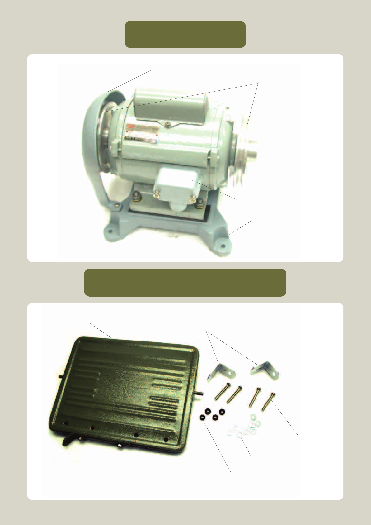
MAIN FEATURES FOR THE COMPONENTS (Main Body)
1. Drilling Roller
– To drive the Drilling Chuck with a maximum speed of 16,000 R.P.M.
2. Pearl Clamp
– To mount up the Clamping Head in proper position.
3. Mounting Handle
– To control the movement of Pearl Clamp for mount up or release the Pearl.
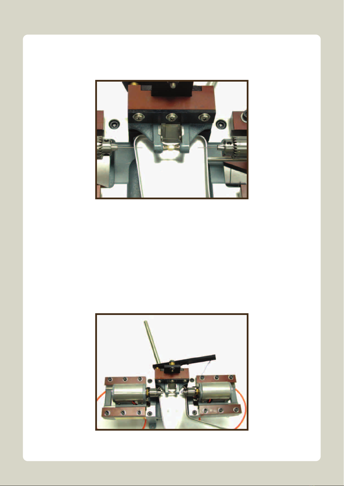
4. Drilling Chuck
– To mount up the Ground Bit Insert in proper location.
5. Bench Top
– Support the drilling machine on the worktable and minimize the vibration while
operating.
6. Locking Screw
– For locking the Transfer Pan on the drilling machine.
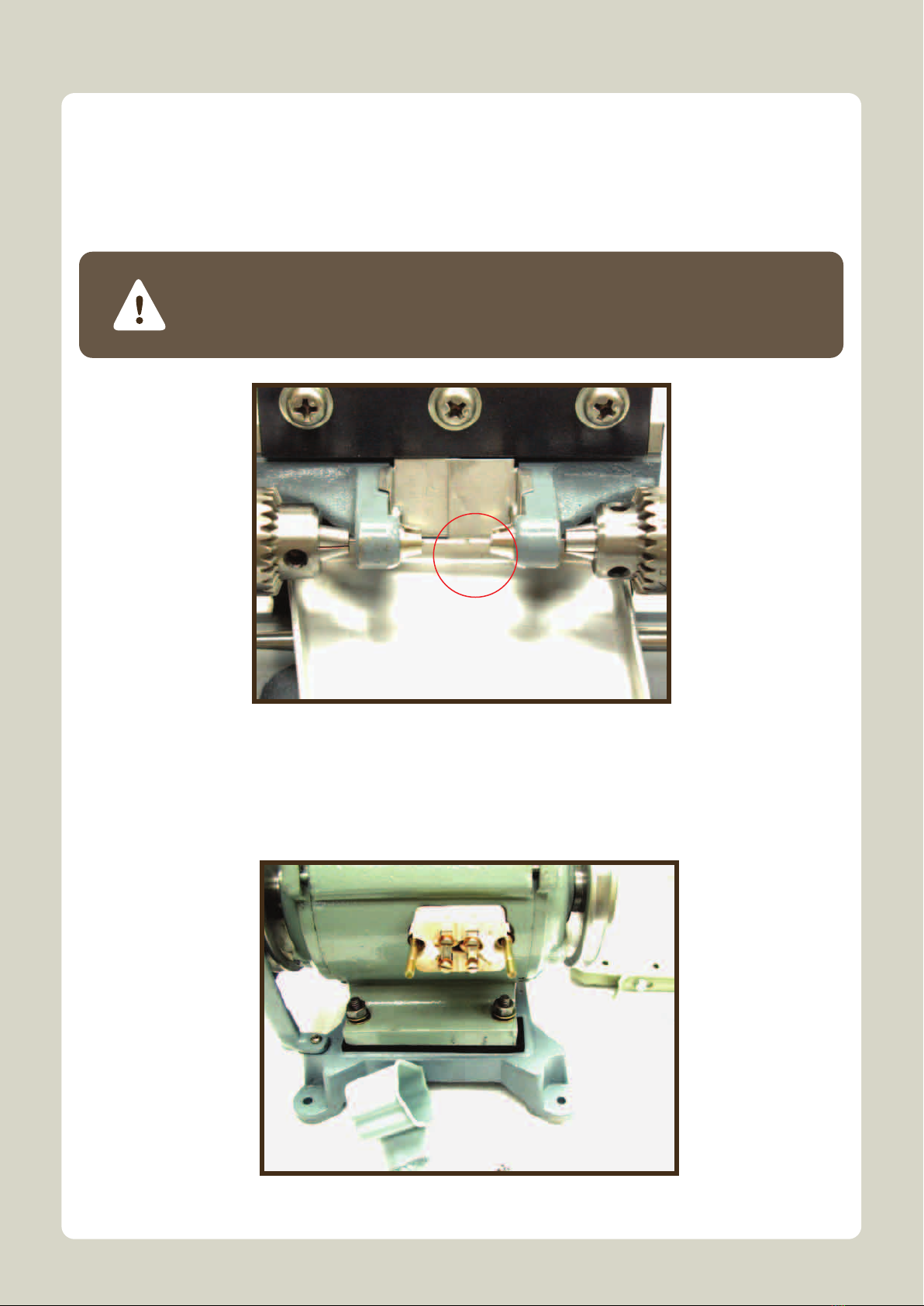
7. Location Pin
– To adjust the minimum length between the ends of two Ground Bit Inserts in order to
avoid collision when drilling.
8. Rotary Belt
– To connect the Pulleys between the Driving Motor and the Drilling motor.
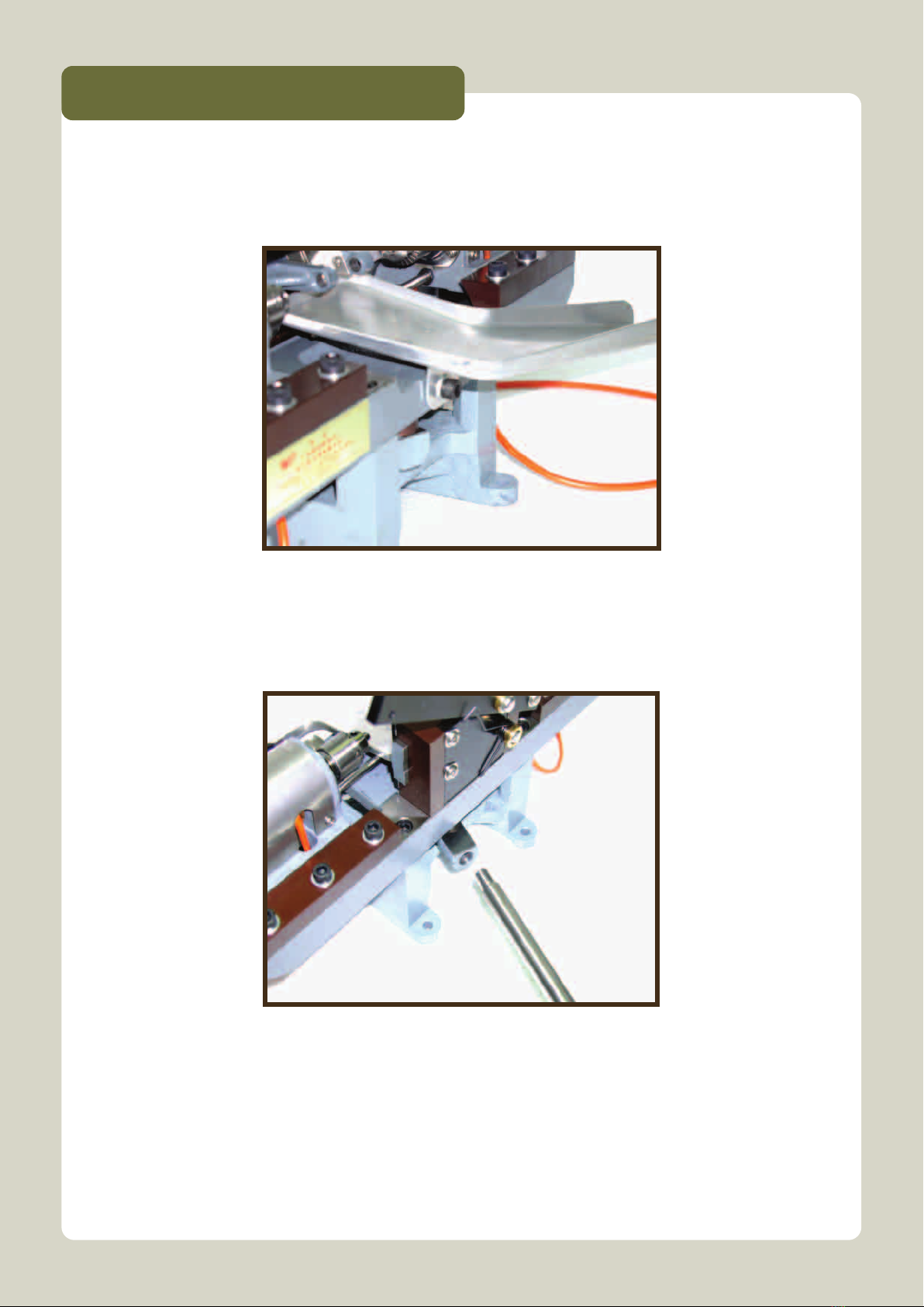
9. Drilling Handle
– For control the movement of Drilling Motors to drill the Pearl.
10. Transfer Pan
– For storage and transporting drilled Pearls.
11. Round Head Bolts
– For fabricate the drilling machine on the worktable.
12. Rings
– For fabricate the drilling machine on the worktable.
13. Plastic Pad
– Supporting the drilling machine on worktable and absorbing vibration.
14. Nuts
– For fabricate the drilling machine on the worktable.
15. Chuck Key
– For locking the Ground Bit Inserts on the Drilling Chuck.

Driving Motor
Driving Motor Accessories
1. Pulley x 2
2. Power Source Cover
3. Mounting Stand
4. Protective Case
5. Stepping Pan
6. L-Joint X 2
7. Round Head Bolt X 4
8. Rings X 8
9. Nuts X 4

MAIN FEATURES FOR THE COMPONENTS (Driving Motor)
1. Pulley
– To drive the Drilling Roller by connecting with the Rotary Belt.
2. Power Source Cover
– To protect the voltage terminals and avoid current leakage.
3. Mounting Stand
– For connecting the Driving Motor on the worktable.
4. Protective Case
– To prevent the Rotary Belt fly off from the Pulley while operating.
5. Stepping Pan
– For controlling the movements of the Pearl Clamp by human footstep operations.
6. L-Joint
– To link up the Stepping Pan and the base of worktable.
7. Round Head Bolts
– For fabricate the Driving Motor on the worktable.
8. Rings
– For fabricate the Driving Motor on the worktable.
9. Nuts
– For fabricate the Driving Motor on the worktable.

PROCEDURES FOR ADJUST THE PEARL CLAMP DISTANCE
screw (Part A)
pearl clamp handle
(Part B)
pearl clamp
distance (Part C)
Figure 1
Figure 2
1) Unlock the screw of part A (See Figure 2)
2) Push out of the part B, then… (See Figure 2)
3) You can change the distance of the pearl clamp (See Figure 1)
4) After fit your pearl size then you can lock the screw again.
The operation procedures of using WTD 002 is equal to WTD 001.
This is a professional design which is ideal for drilling the longer pearl. Therefore, Auto-
matic adjustment of the pearl clamp is very important. You can see the different of the
pearl clamp distance which already shown on picture 1

OPERATION PROCEDURES
Step 1.
Figure 1
Step 2. Mount the Drilling Handle at the back of the drilling machine.
(See Figure 2)
Figure 2
Place and Mount the Transfer Pan onto the drilling machine by using the
Locking Screw. (See Figure 1)
Place the suitable pair of Clamping Heads on the Pearl Clamp to fit the
Pearls for drilling.
Install and mount the Ground Bit Insert # on the Drilling Chuck by use of
the Chuck Key.
Step 3.
Step 4.

Press the Mounting Handle slightly, push the Drilling Handle to the left end
side, adjust the Ground Bit Inserts (use of Chuck Key) at the center posi-
tion and make sure that the distance between two ends of Ground Bit
Inserts is about 1 mm. (See Figure 3)
Caution:
Please mention that this step must be done before operation, otherwise
two ends of Ground Bit Inserts will collide and damage when drilling.
Step 5.
Figure 3
Figure 4
Step 6. Open the Power Source Cover of the Driving Motor. Connect the input
power cables and adjust the suitable input voltage that adopted in local-
ized voltage standard by arranging the metal strips. (See Figure 4)

Figure 5
Figure 6
Note: The voltage selection methods are shown as Figure 5.
D1 and D2 are known as the input terminals.
Note: The worktable and the switch box shown in Figure 6 are not
provided. The layout and the dimensions of the worktable sur
face are shown in Appendix.
Close the Power Source Cover. Assembly the Main Body and the Driving
Motor on the worktable. (See Figure 6)
Step 7.

Step 8. Place the pearl between the two Clamping Heads. Clamp the pearl on the
Clamping Heads by stepped down the Stepping Pan. (See Figure 7)
Figure 7
Pull out the Drilling Handle to the Right end to ensure that the Ground Bit
Inserts are located away from the pearl.
Connect the power plug onto the power socket. *
Turn “ON” the power switch.
Push the Drilling Handle towards LEFT end slowly and start to drill the
pearl (See Figure 8).
Step 9.
Step 10.
Step 11.
Step 12.
Figure 8

Continue to drill the pearl until the Drilling Handle is being pushed to the
LEFT end and the Location Pin collided with the adjustable screw.
Step 13.
Pull back the Drilling Handle to the RIGHT end and turn “OFF” the switch
box.
Release the Stepping Pan due to squeeze the Pearl Clamp. The drilled
pearl will fall onto the Transfer Pan and transport to the container
Caution:
If user found out the Pearl cannot be drilled through, please adjust the
Compensation Screw (See Figure 9) which is at the right bottom side of
the main body to adjust the suitable compensation distance between
two Ground Bit Inserts when drilling.
Figure 9
Step 14.
Step 15.
# The Ground Bit Insert must be ground well before use, otherwise it cannot
drill any hole and will burst out! The grinding method and the sample of the
ground bit insert are shown in appendix.
Please read the specification label on the Driving Motor carefully and
ensure that the input voltages must fit in the current country. Otherwise,
using incorrect input voltages can damage the machine!
Please ensure the Power Switch is on the “OFF” position before connecting
the power source!
* Caution!
1.
2.

APPENDIX
THE LAYOUT OF THE WORKTABLE TOP SURFACE
SAMPLES FOR THE GROUND BIT INSERTS
Figure 10
Figure 11 Figure 12

附錄
APPENDIX
DIMENSIONS OF THE GROUND BIT INSERT
SAMPLES OF THE DRILLING HEADS
Figure 13
Figure 14

Copyright 2010 © Wing Tung Machinery Factory. All right reserved.
永東機械廠
WING TUNG MACHINERY FTY.
SPECIFICATIONS
Drilling Hole Sizes Range (dia.)
Clamping Object Size (dia.)
Maximum Drilling Speed
Motor Power
Input Voltage
Net Weight (Main body + Motor)
Main Body Dimension
0.5 – 3.0 mm (Ground Bit Insert is no provided.
Please prepared by own or additional purchase)
2.0 – 36.0 mm (Clamping Head is no provided.
Please prepared by own or additional purchase)
16,000 R.P.M.
200 W
110V or 220V
23 Kg
340 mm x 340 mm x 180 mm (D x W x H)
This ultra-precision machine must be maintained from time to time.
The engine oil #40 should be used and refueled each 4 hours.
This machine must be cleaned daily to keep it running smoothly.
The belt must be cleaned from time to time to keep the proper operations.
* NOTE
1.
2.
3.
4.
Table of contents