XCVario XCTouchNav 7 User manual


Table of Content
1. Description..............................................................................................................................................................3
2. Features....................................................................................................................................................................4
3. Overvie .................................................................................................................................................................5
4. Operation.................................................................................................................................................................6
4.1. Local flight.......................................................................................................................................................6
4.1.1. Prior to takeoff.........................................................................................................................................6
4.1.2. Inflight:.....................................................................................................................................................6
4.1.3. After landing:...........................................................................................................................................6
5. XCSoar....................................................................................................................................................................7
6. Bluetooth.................................................................................................................................................................7
7. Wireless LAN..........................................................................................................................................................8
8. Installation...............................................................................................................................................................9
8.1. Electrical connections rear.............................................................................................................................10
8.2. 12V DC Po er...............................................................................................................................................10
8.3. USB................................................................................................................................................................11
8.4. Audio Out.......................................................................................................................................................11
8.5. RJ45 connector ttyS3.....................................................................................................................................11
8.6. RJ45 connector ttyS7 and ttyS9.....................................................................................................................12
FLARM.......................................................................................................................................................13
KRT2 Radio.................................................................................................................................................14
8.7. Electrical connections lo er side..................................................................................................................15
8.7.1. DC..........................................................................................................................................................15
8.7.2. USB Type-C...........................................................................................................................................15
8.7.3. USB 3.0..................................................................................................................................................15
8.7.4. Earphone (Jack).....................................................................................................................................15
8.7.5. SD (slot)................................................................................................................................................15
8.8. Comparison IGC- and FCC Standard............................................................................................................16
9. Technical specifications.........................................................................................................................................17
10. Maintenance........................................................................................................................................................18
11. Warranty Policy...................................................................................................................................................18
12. Permit..................................................................................................................................................................19
13. Limitation of Liability.........................................................................................................................................20
14. CE Declaration of Conformity............................................................................................................................21
Page 2

1. Description
The XCTouchNav is a modern device based on Android operating system ith ired serial and ireless interfaces
as Bluetooth and WiFi to run applications such as XCSoar, LK8000 and more. It has a high-resolution sunlight
readable IPS type display that can perfectly be read at almost any vie ing angle.
Optionally a FLARM or another source for NMEA (GPS) data can be connected to the XCTouchNav directly.
The application does not only reads data from loggers, it can also declare tasks there, settings can be changed e.g.
the baud rate of a FLARM or aircraft type and also the IGC log of the flight can then be read out.
By standard, the installed soft are is XCSoar that offers many features. Thanks to a gro ing library ith lots of
glider polars, the soft are can be adapted to almost any glider. Since the XCSoar soft are source code is public
available on github, developers can clone the soft are and further develop their o n features and ideas.
In connection ith a variometer system, mostly the XCVario here is explained, e.g. true airspeed TAS can be
calculated ith the outside temperature (OAT) and the precise altimeter ithout hysteresis together ith the TE
vario signal allo s final flight calculations ith high reliability. An important feature is the ind calculation that
can already be provided by XCSoar together ith a GPS source, circling ind or zigzag ind provided by
XCSoar is fairly good enough in flat land and furthermore improves the final flight precision.
It is very easy to operate XCSoar ith the touchpanel, much more easy than a device ith several rotary knobs at
any corner that do not operate intuitive and need study and practice. The device has an anti-glare and anti-
fingerprint surface already. Normally no extra protection is required.
The system hich is manufactured in large numbers is not expensive, comes readily built up and tested (no self
craft set), is an excellent addon for any glider cockpit ith already a FLARM device or a smart variometer
installed and keeps being extensible ith a large number of ired and ireless interfaces.
Page 3

2. Features
•Black anodized aluminum providing effective shielding of EMV
•Po er supply directly from 12V ith the onboard electrical system
•Po er consumption typically 6 W (465 mA at 12.9V) and 4 W for the 5.7 inch variant
•Android 11 incl. Play Store
•Wireless interfaces: WiFi (802.11b/g/n) and Bluetooth (BT4.0)
•IGC compatible serial interfaces (1xDTE, 2xDCE)
•4 multichannel USB-A type 2.0 ports plus one LAN port
•1 USB-A type 3.0 port plus one USB-C port on the side
•USB Devices can be po ered from the USB-A ports (max 1A = 5W)
•Micro SD memory card slo , max 32G
•3.5 mm jack socket for headphones
•A stereo po er amplifier 3 W
•5.1 mm coaxial DC po er jack
•Builtin fan for lo CPU core temperature
•16 GB Flash memory, 2 GB Ram
•1.8 GHz Quad-Core CPU
•Multipoint touchscreen display 1024×600 pixel
•1200 nits brightness in high contrast IPS technology for best sunlight readability
•Anti-glare and anti-fingerprint coating
•XCSoar is pre-installed
•Significantly more performance, more connectivity and user-friendliness than other system available in the
market
Page 4

3. Overview
The follo ing overvie sho s the embedding of the XCTouchNav in the cockpit environment.
The standard case and most common case is the connection ith an XCVario to the serial interface
(recommended), that is connected itself to a FLARM. The second port of the Y-Piece may server for another
device like a FLARM Traffic vie er.
Page 5

4. Operation
This chapter is taken from XCSoar manual, and provides basic instructions for using XCSoar in a typical local
flight. It ill demonstrate ho to use key features. It assumes the configuration options have already been set up
to the user’s preferences. These instructions are intended to provide a simple step-by-step guide to flying tasks of
varying levels of complexity but are not intended to demonstrate all the features of XCSoar. Furthermore, the
system can be used productively in ays other than as described here.
For more information please refer to the XCSoar manuals that are provided online here:
https:// .xcsoar.org/discover/manual.html
4.1. Local flight
In this scenario, the pilot intends to fly locally or a casual cross-country task here navigation to pre-determined
aypoints is not required.
4.1.1.Prior to ta eoff
1. Turn on the device
2. Open the Flight Setup dialogue and adjust the bugs and ballast as required. Set the maximum forecast
temperature. Close the dialogue
3. Open the Task Edit dialogue, and create a blank task by pressing Ne
4. Select “Touring” as task type.
5. Once the task is created, move the cursor to the “add aypoint”item and press enter. Select the start
aypoint from the list, e.g. first item is the home base, and press enter. Press close or escape.
6. Select another one “add aypoint”, and enter the same aypoint as finish point.
7. No the task contains one aypoint to home.
4.1.2.In flight:
At the appropriate times, set the MacCready manually from the menu, task calculator or from the variometer.
Change the bugs/ballast settings as required.
At any time, the glider can reach home hen the altitude difference bar is a green arro pointing up ards.
Optionally, activate MC Auto hen ready to return home.
If the MacCready mode as set to “Final Glide” or “Both”, then the system ill command the optimal speed to
return home.
4.1.3.After landing:
The Status dialogue sho s the elapsed flight time.
The analysis dialogue can be used to analyze or revie the flight.
The IGC logger replay can be used to replay the flight.
These actions may be performed after turning the device off and on again.
Page 6

5. XCSoar
XCSoar is free open source soft are optimized for Android systems ith a touch screen and comes pre-installed
on the XCTouchNav. To launch the preinstalled XCSoar ipe screen once to the right in order to see installed
apps, then tap on the icon for XCSoar to start the application.
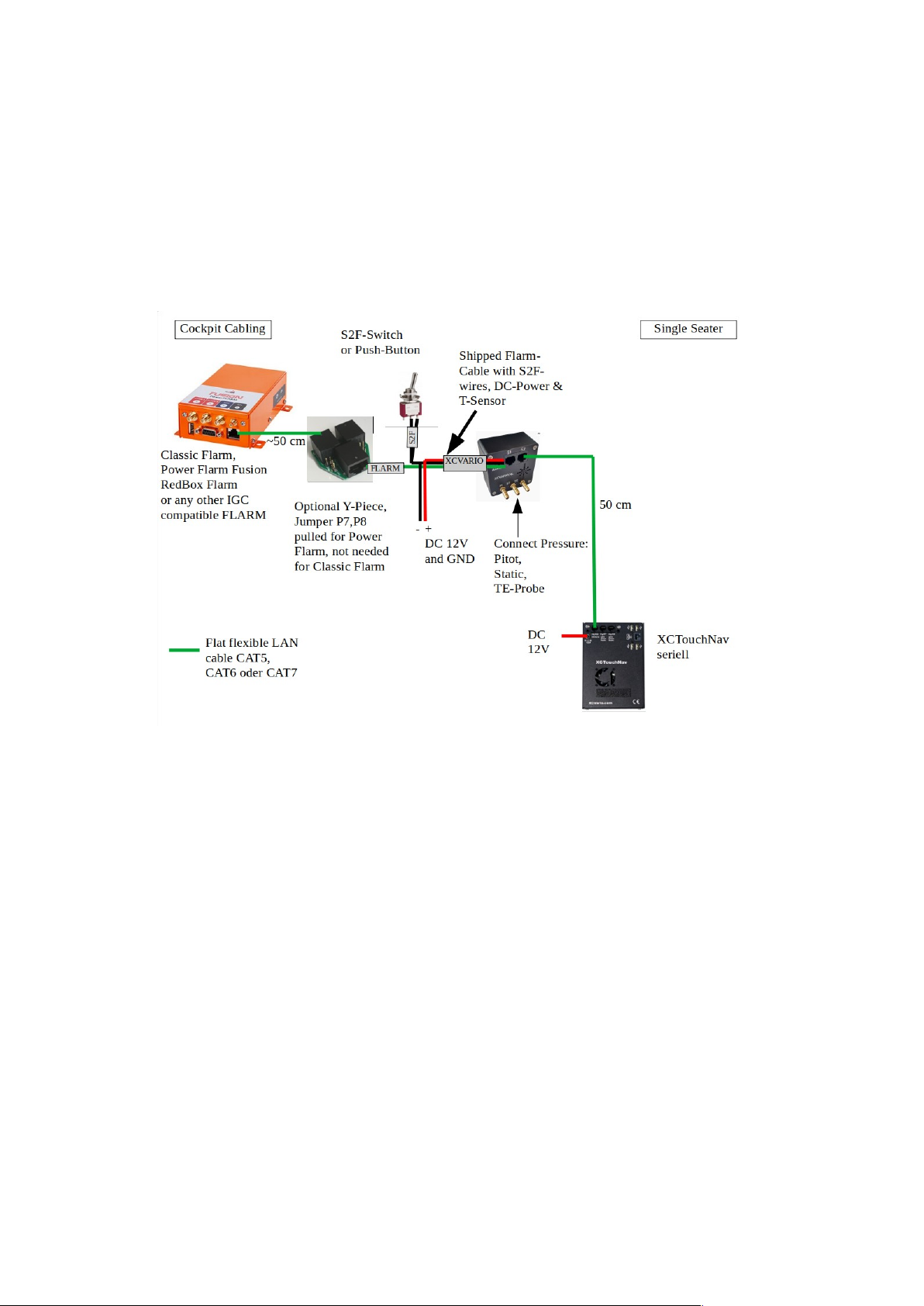
For a complete glider flight computer, ho ever, further values such as GPS fixes, the dynamic pressure, TE
nozzle pressure, static pressure are needed in order to be able to get an indication for an optimal speed to fly,
precise final glide or moving map. The XCVario ith a FLARM connected delivers exactly this data that can be
provided by a RS232 serial cable connection (recommended ay) or ireless via WiFi or Bluetooth.
If you don’t o n a FLARM, there is a cheap GPS module provided in the shop, that can be used instead of
FLARM.
Mean hile smartphones or tables are available on the market and may be suitable in terms of display brightness,
contrast and feature a touchscreen, those devices may have issues at higher temperatures and ill shut do n in the
cockpit already before flight hen canopy is closed and temperatures rises above 40° C. The XCTouchNav
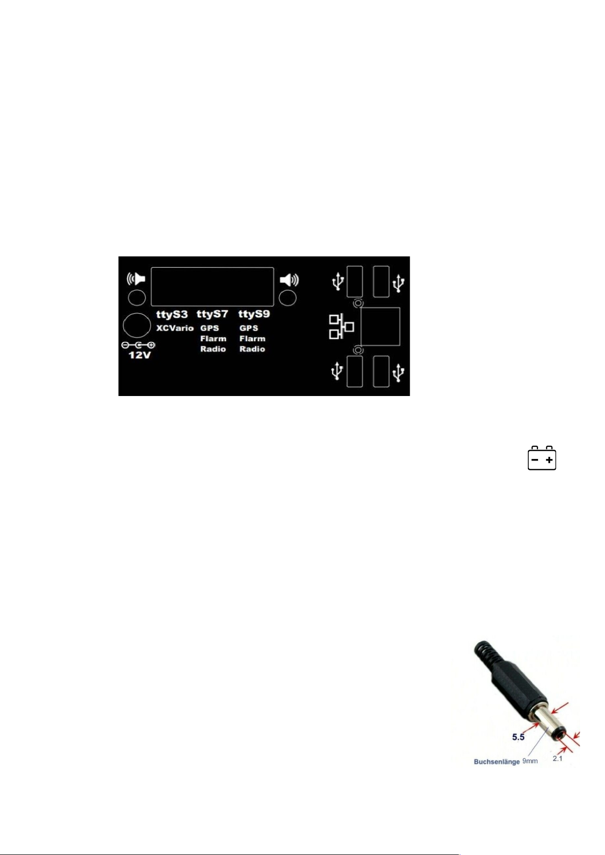
operates directly on the 12V on board grid, no DC converter is needed, is tested until 70° C and on’t face you
ith the danger to shut do n from a lipo battery overheat.
With the XCTouchNav, advanced technology is available at an affordable price.
XCTouchNav running XCSoar, offers a perfect glider computer ith the latest technology, quad core CPU,
intuitive touchscreen operation, many screens full of features, flight planning, final approach and freely
configurable info boxes, beside display of terrain ith airspace including side vie . Of course topography and
landing fields are easy to be setup. There is a thermal assistant for centering thermals, audio variometer ith ith
external speakers, speed to fly command according to your MC setting or assistance for dolphin cross country
speed and more.
6. Bluetooth
In order to establish a connection via Bluetooth, the XCTouchNav needs to pair ith the device.
To do this, perform a device scan in the Android device setup under Bluetooth, and pair your
device e.g. an XCVario variometer, hich should appear there in the device list as e.g. XCVario-
5678, in the pairing dialog.
If a Bluetooth pass ord is requested for an older device, try to enter "1234", ne er Bluetooth
standards on’t require this.
Then in XCSoar under Configuration/NMEA connection, setup a ne device A..F. Any paired device can be
found in the 'Connection' field ith its Bluetooth ID. Select this there and in the follo ing dialog enter the desired
driver, for current XCVario versions "XCVario". The s itch K6Bt remains in the 'off' position. After you have
ackno ledged the dialog ith “OK”, XCSoar ill connect to the device ithin a fe seconds, hich ill then
appear as a regular NMEA connection, e.g. ith the status “connected: Baro,Vario,Environment[,FLARM]”.
The relevant records of the device should no be visible under 'Monitor'. For details regarding the data there
please refer to the manufacturers handbook for the corresponding device. You can paired several different
Bluetooth devices via Bluetooth protocol.
Page 7

7. Wireless LAN
In order to set up a ireless LAN connection (also called ireless LAN, WLAN or WiFi),
e.g. to a variometer, here explained ith the XCVario, the device must activate the
“Wireless LAN” in Setup/Options/Wireless. After that, you can connect to the
corresponding WiFi net ork ID of this device in your XCTouchNav WiFi settings. The
net ork ID of the XCVario is identical to the Bluetooth ID, e.g. XCVario-5678. To
connect ith the secured WiFi (https) it is required to enter the pass ord as documented
in the manufacturers handbook of the device.
Page 8

8. Installation
The device can be installed ithin the instrument panel ith a corresponding cutout,
dimensions see technical data section. The 7 inch model comes ith t o holders that are to
adjustable in height so can be adapted to various panel sizes. The 5.7 inch model has
threads in the front plate already, and can be scre ed directly from the backside of the instrument panel. Scre s
needed to attach the display to the instrument panel are M2.5x10 typical, maybe longer if panel thickness requires.
7 Inch:
5.7 Inch:
Page 9

Note: After installation in the corresponding orientation, screen rotation has to be s itched off in the Android
settings of the device, in order to avoid turning of screen from g-forces:
1. Wipe do n screen to lift up Android Quick Setup menu
2. Tap the „Autorotate“ icon to toggle Autorotation status as deactivated
8.1. Electrical connections rear
The electrical connections are similar in both models, just the arrangement is a bit different in the 5.7 inch model
here the connector block for USB and LAN horizontally and belo the the serial ttyS3..9 connectors.
8.2. 12V DC Power
The po er supply is normally is connected to the on board electrical system. A single fuse for a
device is not mandatory for gliders, but is recommended. The iring can be done ith copper strands from 0.5
mm², 1 mm² is recommended. Alternatively, the navi can be connected in parallel to another device that is fused
ith at least 1 ampere. The device must be protected because the plug and cable are not designed for higher
currents. The device tolerates voltages in the range of 10-18 volts, a supply of 12 volts is ideal. If the device is
operated ithout any protection plus an external short circuit, e.g. at ttyS7, internal damage is not expected,
current is limited by a 0.5 Ampere self resettable fuse.
The navi is protected against polarity reversal and is internally protected against transient over-voltages such as
ESD discharges and induction peaks hen starting. In general, the avionics should be left s itched off hen
starting, if it cannot be avoided, e.g. hen starting the engine during the flight, you have to rely on the over-
voltage protection.
The 12V DC Po er connector is a 5.5 mm standard coaxial DC po er connector.
The inner hole is 2.1 mm. One connector is shipped ith the device. This connector
features a high holding force so ill not disconnect at high g-loads. For po er
connection a cable ith 1 mm² copper strand is recommended.
Note: To save space in the instrument panel, there is no po er s itch in the
XCTouchNav. In order to disconnect from po er, connect the device either to an
Page 10

existing s itch in the panel, already the main s itch ill do, hence e recommend an extra s itch to po er off
the device individually e.g. on lo battery po er, or if not needed.
8.3. USB
There are four USB 2.0 interfaces, each of them can deliver 500 mA, in total 1.5 A can be
dra n if the fuse used for the XCTouchNav features at least 2 Amperes.
8.4. Audio Out
T o 3.5mm mono jacks offers an external output for the audio signal of the device. If you
need sound from the navigation device, t o external speaker’s ith at least 3W po er can be
connected to there.
Page 11

8.5. RJ45 connector ttyS3
This interface implements the IGC standard on the device site (like a
FLARM is assignment (RJ45) required for the FLARM is available at the
end of the FLARM cable. The RJ45 socket is sho n in the figure above
in a plan vie from the rear. Pin 1 is therefore on the far left. The
minimum connections required to operate the device in its basic function
are sho n in bold.
Interface ttyS3
Pin #
RJ45
FCC
identifier direction Connection
XCVario
1 GND GND
2 GND
3 RS232 TTL RX Serial TX
4 RS232 TTL TX Serial RX
5 NC
6 NC
7 NC
8 NC
NC: Not connected
Page 12
Abbildung 1: ttyS3 Pinout

8.6. RJ45 connector ttyS7 and ttyS9
Both serial interfaces are similar ith standard IGC assignment for the
serial port. This interfaces implement the IGC Standard on the PC site,
so devices like a FLARM can be connected to there.
Any device ith an IGC compatible port e.g. a FLARM or a Logger,
can be connected ith a standard 1:1 LAN cable to here.
Also any other serial device supported by the navi application e.g.
XCSoar, like a radio device can be connected to the serial interface,
pins RX/TX and GND ith a custom cable in case the connected device
does not have a standard IGC RJ45 plug.
This interfaces provide as ell 12V po er on Pin 8, in case this is not ished there are several options:
1. Cut a PCB ire on the bottom of the I/O board, see right
side. Po er on ttyS9 is cut per default. If no po er is
needed on ttyS7 or ttyS9, the PCB can be modified by cuts
as sho n on the right side here:
2. Use a Y-Piece as offered in the shop ith po er jumpers
pulled
3. Use a 8P4C ire ith only Pin 1..4 connected (custom
made), a cable like this ill be available around Q2/23
4. Use a 6P6C ire (RJ12) centered in the RJ45 ports (amazon provides corresponding cables ith RJ12
ends)
Interface ttyS7 and ttyS
Pin #
RJ45
FCC
identifier direction Connection
Logger/Radio/GPS
1 GND GND
2 GND GND
3 RS232 TTL TX Serial RX
4 RS232 TTL RX Serial TX
5 NC
6 NC
7 NC
8 +8..28 V electrical system +12VDC
Page 13
Abbildung 2: ttyS7,9 Pinout

FLARM
FLARM’s ith an IGC compatible serial interface can be connected and po ered by the XCTouchNav ith a 1:1
cable. The maximum current is 0.5 Amperes the XCTouchNav can deliver. This enables the flight declaration or
flight do nload from the FLARM via the navigation application (e.g. XCSoar).
Page 14

KRT2 Radio
The connection to a radio of the type KRT2, or another model if the navigation device (e.g. XCSoar) has a driver
for it, can be established serially via rear interfaces ttyS7 or ttyS9. The baud rate should be set to 600 baud. To do
this, make the connection from the XCTouchNav’s pin 3 and 4 to the corresponding serial RX/TX of the KRT2, it
is best to solder it there to the existing KRT2 Sub-D connector. It is important to ire together al ays RX to TX
and TX to RX as follo s:
XCTouchNav 3 (TX) <-> 13 KRT2 (RX)
XCTouchNav 4 (RX) <-> 2 KRT2 (TX Remote)
XCTouchNav 1 (GND) <-> 1 KRT2 (GND)
Page 15

8.7. Electrical connections lower side
There are several electrical connections on the lo er side that may be used,
hence normally those should not be needed as usually space is limited in the
instrument panel and there are similar connection on the rear side for USB,
Po er and Audio, hence there might be special applications for this.
8.7.1.DC
The same purpose that the DC connector at rear side to feed 12V DC into the
device, hence a 3.2 mm coaxial plug is needed.
8.7.2.USB Type-C
USB type C interface
8.7.3.USB 3.0
Can charge devices up to 500 mA.
8.7.4. Earphone (Jac )
Lo po er standard stereo earphone Jack 3.5 mm
8.7.5. SD (slot)
SD card slot, for specification see section ith technical data.
Page 16

8.8. Comparison IGC- and FCC Standard
The RJ45 sockets are numbered in the document according to the international standard of the Federal
Communications Commission (FCC). Beside the FCC standard, there is also the International Gliding
Commission (https:// .fai.org/commission/igc) that has defined a standard for the interfaces of IGC loggers.
The XCTouchNav interface follo s the IGC standard, but primarily uses the standard FCC numbering in this
document.
Figure 4 on the left sho s the FCC standard, hich designates the first pin in the top vie of the connector as pin
8. Next to it on the right in Figure 5 is the rongly numbered IGC standard (source: TECHNICAL
SPECIFICATION FOR IGC-APPROVED GNSS FLIGHT RECORDERS - Second Edition
ith Amendment 7 31 January 2022). There the numbering of the first pin on the connector on the left begins ith
pin 1 (!).
In order to assess hether the pin assignment of a device fits, hen reading a document it is therefore al ays
necessary to check hich standard the numbering follo s, it is the IGC standard, the + 12V are numbered ith
pins 1 and 2 on the left in the top vie of the plug, ith the FCC By default, the +12V are of course also on the
left, but are numbered ith pins 7 and 8. Belo is the table ith a comparison of both numbering systems ith a
comparison.
The IGC's incorrect numbering, hich differs from the FCC, causes confusion in many cases. Manufacturers all
over the orld number components, CAD symbols or cables are all according to the FCC standard, as do avionics
equipment manufacturers mean hile again in there documentation. You cannot estimate hether the assignment
is correct ith the pin number alone. A dra ing of the connector must therefore al ays be taken into account.
Comparison of the pin numbers of the FCC and the (reversed) IGC standard:
Signal RJ45 FCC Standard Pin# RJ45 IGC Standard Pin#
Volts + 7+8 1+2
Data out (TX) 4 5
Data in (RX) 3 6
Earth (GND) 1+2 7+8
Page 17
Abbildung 3: FCC-Standard
Abbildung 4: IGC-Standard (re ersed)

9. Technical specifications
Operating System Android 11 ith Play Store
Wireless Interfaces WiFi 2.4 GHz
Bluetooth 4.2
Serial Interfaces 3x Serial, 4800..115200 Baud
1xDTE, 2xDCE USB
USB Interface 4 x USB 2.0 accessible on the rear and
1x USB 3.0 on the side
LAN Interface LAN 100/1000 Mbit Ethernet RJ45
LAN connector
Audio Interface Audio 2 x 3 Watts Stereo
2 Mono Audio Jack’s 3.5 mm
Memory 16GB Flash, 2GB Ram, micro SD card
can be added
CPU Quad Core 1.8 GHz
Display 1024×600 pixel high bright 1200 nits
and high contrast IPS technology
Po er consumption
(typical)
5.7 Inch 4 W or 320 mA at 12.8 V
7 Inch 6 W or 465 mA at 12.8 V
Panel-Cutout size 5.7 Inch
7 Inch 100 x 164 mm
Dimensions 5.7 Inch 141x104x34
7 Inch 175x115x28
Weight 5.7 Inch 405 g
7 Inch 490 g
Page 18

10. Maintenance
The device does not require any maintenance. Storage shall not be done in a humid environment. Ensure that
relative humidity ill not exceed 100% in order to avoid condensation.
11. Warranty Policy
For the Navi, the manufacturer provides a guarantee of t o years from the date of purchase ith regard to the
effort and material costs of the repair. Within this period, components that fail under normal operating conditions
ill be repaired or replaced free of charge, provided the device as sent to the manufacturer free of charge.
The arranty does not cover damage resulting from misuse, abuse, accidents, unauthorized modifications or
repairs, proven incorrect or faulty iring, over-voltage or fire.
According to the German Civil Code, the return can be made ithin 14 days of the date of purchase. In this case,
the device and its accessories must be returned by the buyer to the address from hich it as delivered. The buyer
bears the costs for this.
Page 19

12. Permit
For each instrument, if the equipment is part of the minimum equipment list or requires approval, it may only be
installed if the supplier or manufacturer provides a document on the proper check for compliance ith the
respective specification of the individual piece of equipment, area of EASA this is usually the EASA Form One.
For all other equipment, as ell as for standard parts, a corresponding examination and documentation of the
same is not required (e.g. device, final approach computer, flight data recording devices, navigation computer,
additional antennas, batteries, cameras, additional pressure probes, mosquito cleaning systems, etc.). This is
regulated in detail by EASA in AMC 21.A.303(c) 2, ith the follo ing ording:
----
AMC 21.A.303(c) Standard Parts
1. In this context a part is considered as a ‘standard part’ here it is designated as such by the design
approval holder responsible for the product, part or appliance, in hich the part is intended to be used. In
order to be considered a ‘standard part’, all design, manufacturing, inspection data and marking
requirements necessary to demonstrate conformity of that part should be in the public domain and
published or established as part of officially recognized Standards, or
2. For sailplanes and po ered sailplanes, here it is a non-required instrument and/or equipment certified
under the provision of CS 22.1301(b), if that instrument or equipment, hen installed, functioning,
functioning improperly or not functioning at all, does not in itself, or by its effect upon the sailplane and its
operation, constitute a safety hazard.
‘Required’ in the term ‘non-required’ as used above means required by the applicable certification specifications
(CS 22.1303, 22.1305 and 22.1307) or required by the relevant operating regulations and the applicable Rules of
the Air or as required by Air Traffic Management (e.g. a transponder in certain controlled airspace).
Examples of equipment hich can be considered as standard parts are, variometers, bank/slip indicators ball type,
total energy probes, final glide calculators, navigation computers, data logger / barograph / turnpoint camera,
bug- ipers and anti-collision systems. Equipment hich must be approved in accordance to the certification
specifications shall comply ith the applicable ETSO or equivalent and is not considered a standard part (e.g.
oxygen equipment).
-----
This means that no EASA Form One is required for the Navi, and it can be installed.
Note:
After installation, the equipment list of the aircraft must be adjusted, and if a relevant change in center of gravity
due to the additional mass of 0.49 kg for the 7 inch model or 0.4 kg for the 5.7 inch model at the mounting place
cannot be considered by a eight an balance calculation, a eighing must be carried out and the change has to be
approved.
Page 20
This manual suits for next models
1
Table of contents