XIAMEN OCULAR OPTICS CO., LTD. 6
SOUTH2/F, GUANGXIA BUILDING, TORCH HIGH-TECH DEVELOPMENT ARER,
XIAMEN 361006.P.R.CHINA TEL: 86-592-5650516 FAX: 86-592-5650695
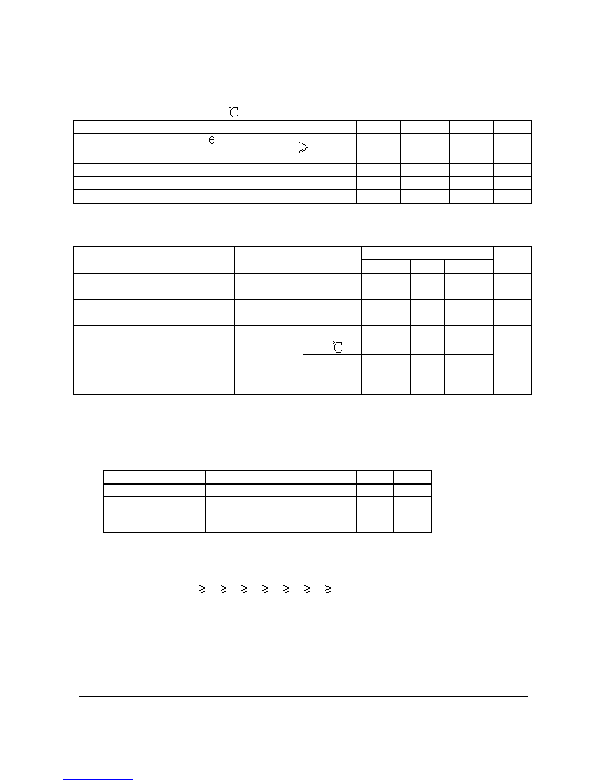
Electrical Absolute Maximum Ratings (KS0108B)
Parameter Symbol Rating Unit Note
Operating voltage VDD -0.3 ~ +7.0 V*1
Supply voltageVEE VDD-19.0 ~ VDD+0.3 V*4
VB-0.3 ~ VDD+0.3 V*1,3Driver supply voltage VLCD VEE-0.3 ~ VDD+0.3 V*2
*Notes:
*1. Based on VSS = 0V
*2. Applies the same supply voltage to VEE. VLCD=VDD-VEE.
*3. Applies to M, FRM, CLK1, CLK2, CL, RESETB, ADC, CS1B, CS2B, CS3, E, R/W, RS and
DB0~DB7.
*4. Applies V0L, V2L, V3L and V5L.
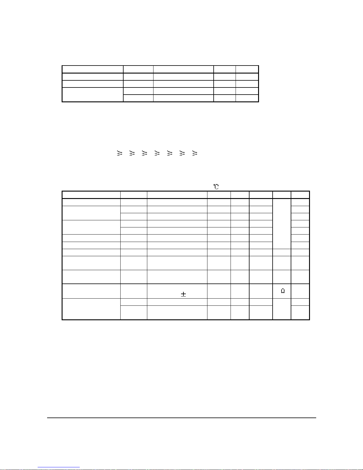
Voltage level: VDD V0 V1 V2 V3 V4 V5 VEE
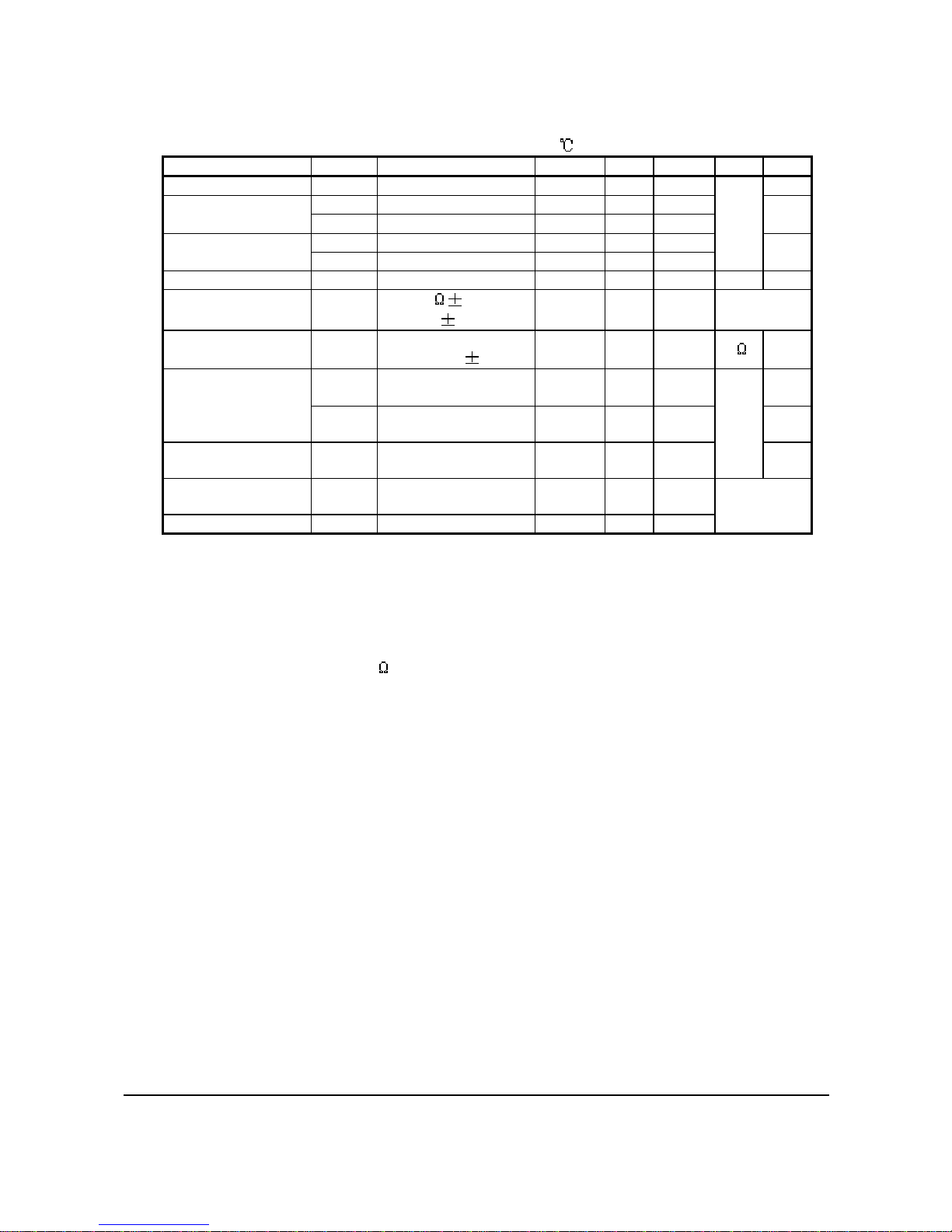
DC Electrical Characteristics (KS0108B)
(VDD= 4.5 to 5.5V, VSS=0V,VDD-VEE=8~17V,Ta= -30 to +85 )
Item Symbol Condition Min. Typ. Max. Unit Note
Operating voltageVDD -4.5 -5.5
VIH1 -0.7VDD -VDD *1
Input High voltage VIH2 -2.0 -VDD *2
VIL1 -0-0.3VDD *1
Input Low voltage VIL2 -0-0.8 *2
Output High Voltage VOH IOH= -0.2mA 2.4 --*3
Output Low Voltage VOL IOL= 1.6mA --0.4
V
*3
Input leakage current ILKG VIN= VSS ~ VDD -1.0 -+1.0 µA*4
Three-state (OFF)
Input Current ITSL VIN= VSS ~ VDD -5.0 -5.0 *5
Driver Input leakage
current IDIL VIN= VEE ~ VDD -2.0 2.0 *6
On Resistance
(Vdiv-Ci) RONS VDD-VEE=15V
Load current 100µA--7.5 k*8
IDD1 During Display --0.1 *7
Operating current IDD2 During Access
Access Cycle=1MHz --0.5 mA *7
Notes
*1. CL, FRM, M, RSTB, CLK1, CLK2
*2. CS1B, CS2B, CS3, E, R/W, RS, DB0~DB7
*3. DB0~DB7
*4. Except DB0~DB7
*5. DB0~DB7 at high impedance
*6. V0, V1, V3, V3, V4, V5
*7. 1/64 duty, FCLK=250KHZ, Frame Frequency=70HKZ, Output: No Load
*8. VDD-VEE=15.5V
V0L>V2L>= VDD-2/7(VDD-VEE)>V3L= VEE+2/7(VDD-VEE)>V5L