Xinje X-NET fieldbus User manual

X-NETfieldbus
User manual
Wuxi XINJE Electric Co., Ltd.
Data No. PD06 20151009 3.2

Catalog
PREFACE X-NET INTRODUCTION ............................................................................................................................................ 3
1X-NET FIELDBUS ............................................................................................................................................................. 4
1-1. FUNCTION SUMMARIZE .......................................................................................................................4
1-1-1. Introduction ...........................................................................................................................4
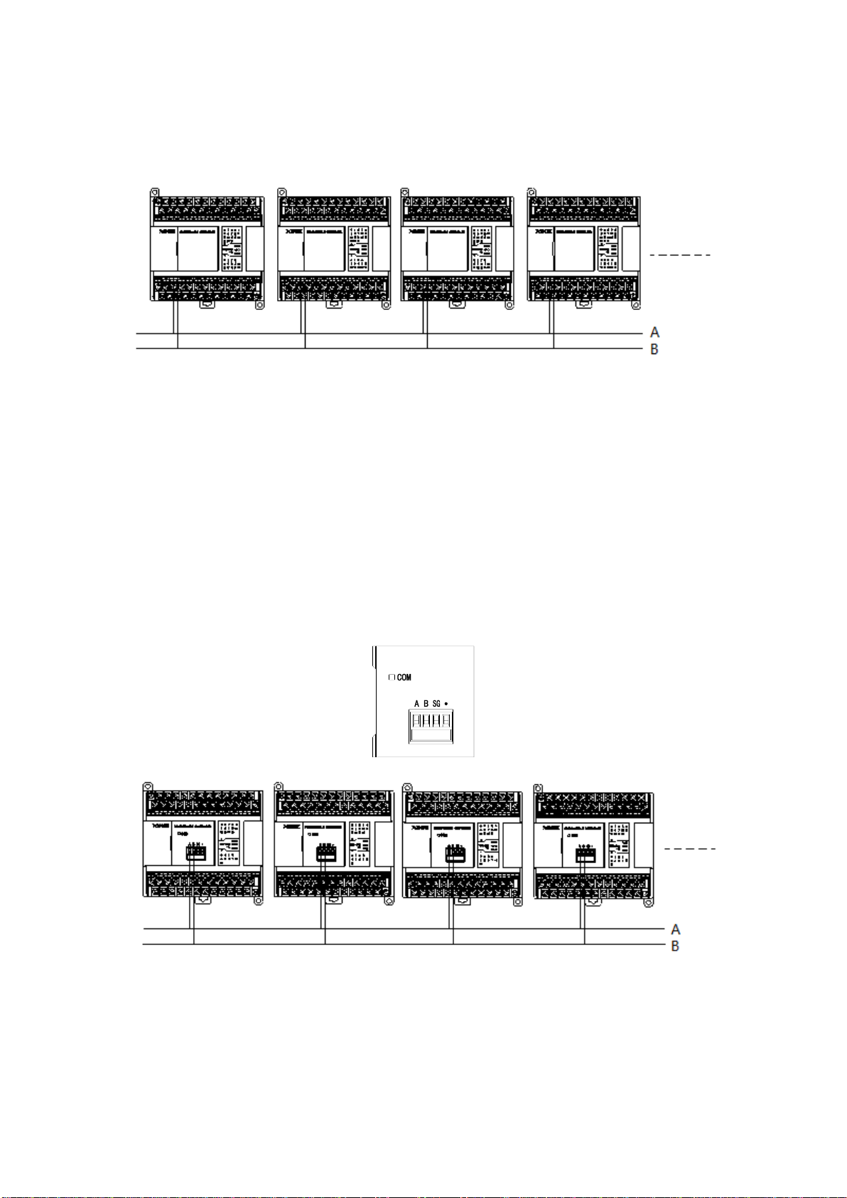
1-1-2. Wiring mode ..........................................................................................................................4
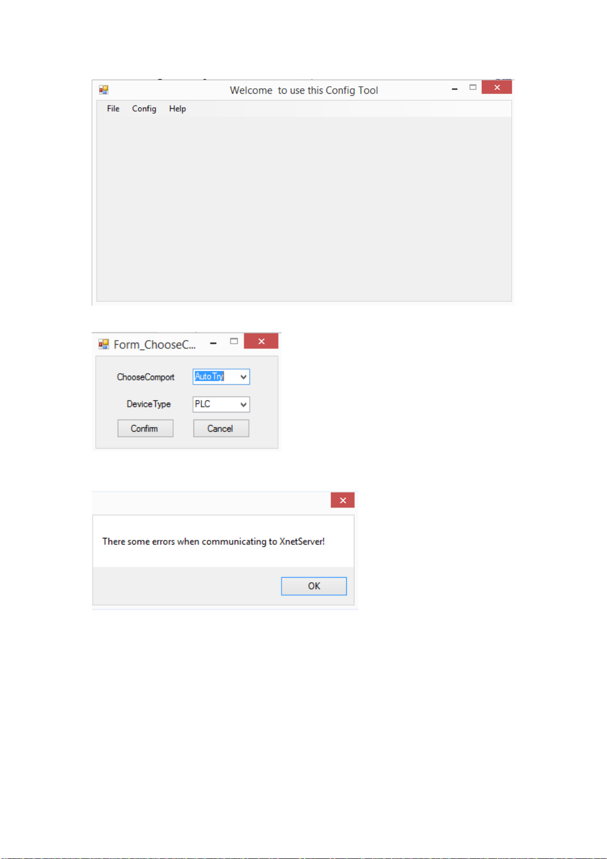
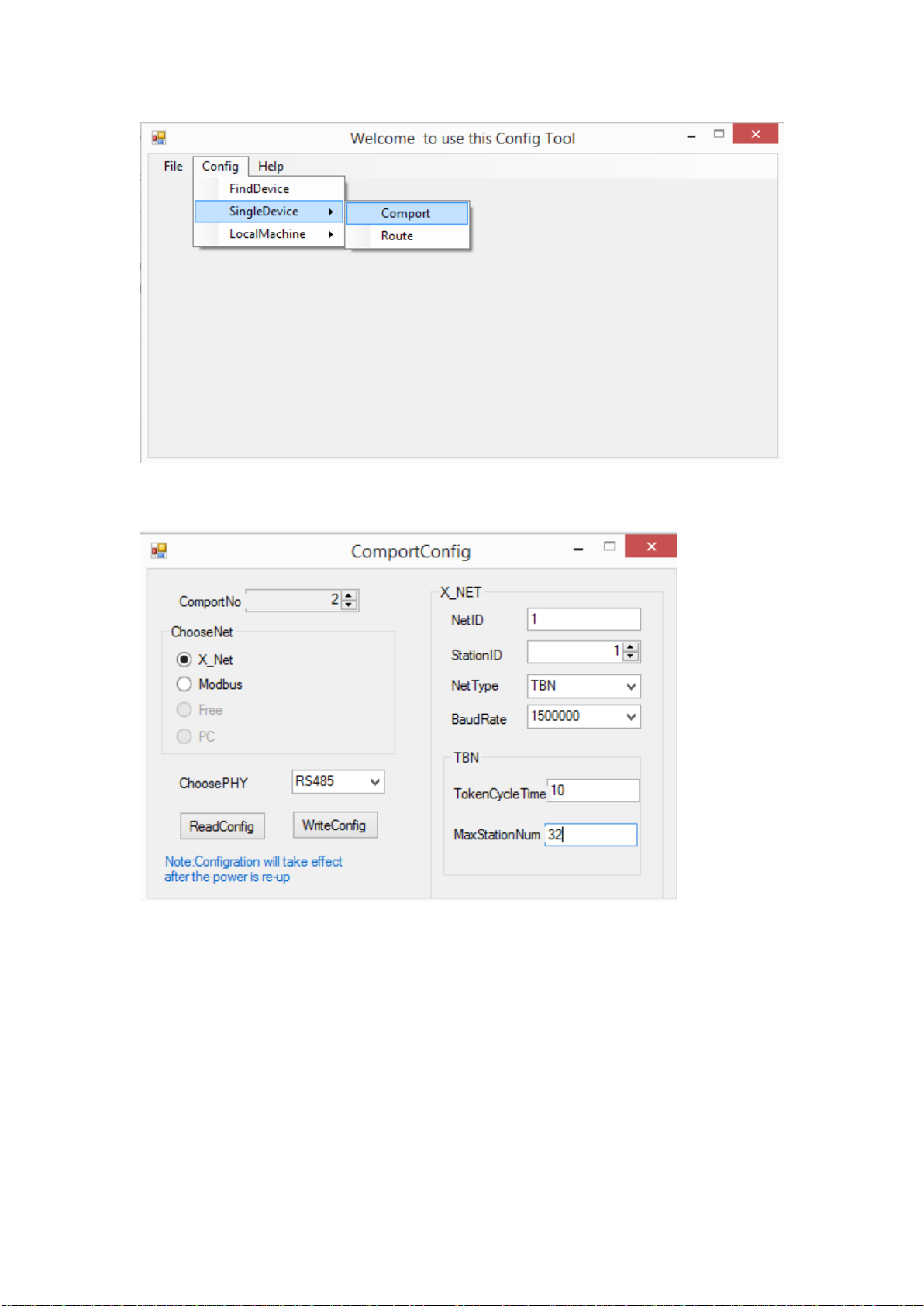
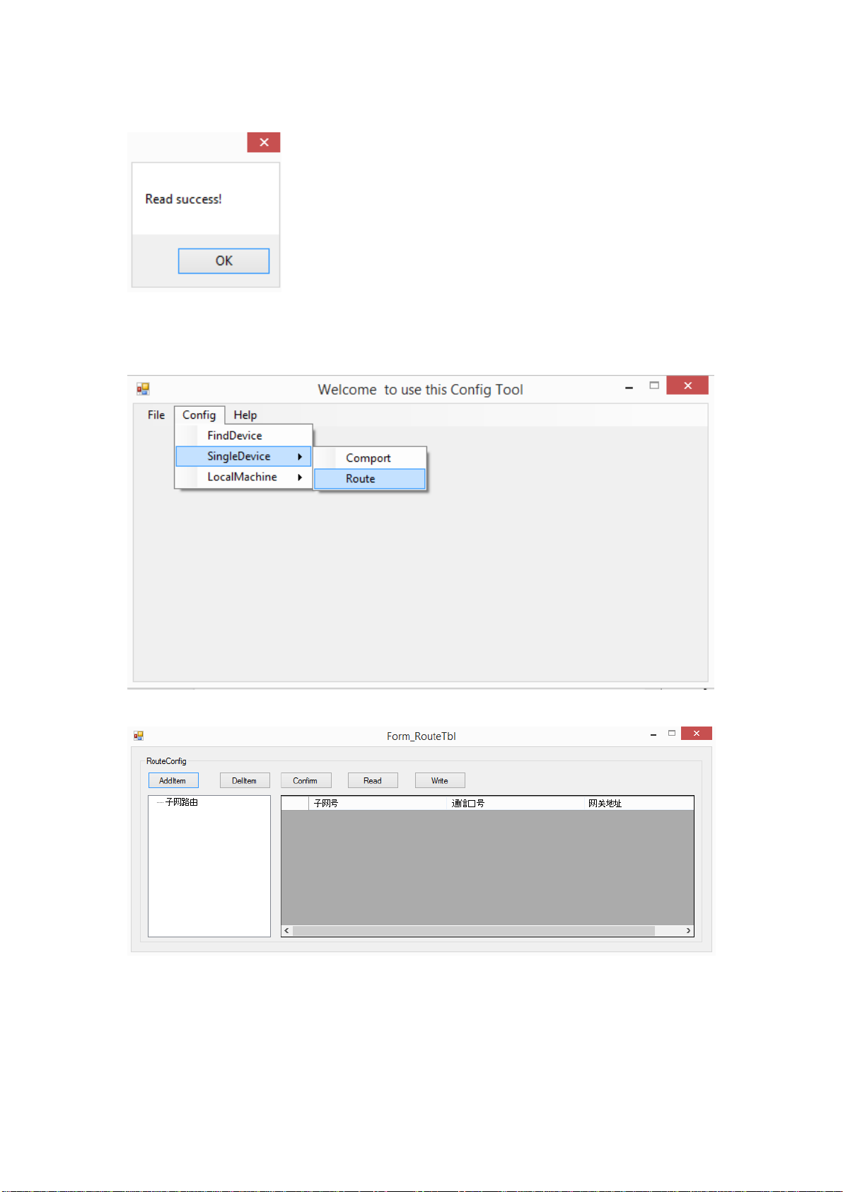
1-1-3. XINJEConfig software .............................................................................................................6
1-2. COMMUNICATION INSTRUCTION ..........................................................................................................10
1-2-1. Read bit [BIT_READ].............................................................................................................11
1-2-2. Write bit [BIT_WRITE] ..........................................................................................................12
1-2-3. Read register [REG_READ] ...................................................................................................13
1-2-4. Write register [REG_WRITE].................................................................................................14
1-3. COMMUNICATION ADDRESS................................................................................................................15
1-4. X-NET COMMUNICATION APPLICATION ................................................................................................22
1-5. COMMUNICATION REGISTER ...............................................................................................................26
2X-NET MOTION FIELDBUS ...............................................................................................................................................29
2-1. FUNCTION SUMMARY ........................................................................................................................29
2-1-1. Special vocabulary ...............................................................................................................29
2-1-2. Fieldbus wiring.....................................................................................................................29
2-1-3. PLC software ........................................................................................................................30
2-2. INSTRUCTIONS .................................................................................................................................30
2-2-1. Incremental position motion [MOTO] ..................................................................................30
2-2-2. Absolute position motion [MOTOA] .....................................................................................35
2-2-3. Multi-speed running [MOTOS] .............................................................................................38
2-2-4. Stop running [MOSTOP] .......................................................................................................45
2-2-5. Continue running [MOGOON] ..............................................................................................47
2-2-6. Synchronous run [MOSYN] ...................................................................................................48
2-2-7. Release synchronous run [MOUSYN]....................................................................................51
2-2-8. Write in present position [MOWRITE] ..................................................................................52
2-2-9. Read present position [MOREAD] ........................................................................................54
3 TEACHING FUNCTION .....................................................................................................................................................55
3-1. SFD REGISTER SETTING......................................................................................................................55
3-2. RETURN THE ORIGIN..........................................................................................................................57
3-3. JOGGING ........................................................................................................................................64
3-4. IN-CIRCUIT EMULATION......................................................................................................................68
3-5. PROTECTION....................................................................................................................................68
4SYSTEM COIL AND REGISTER...........................................................................................................................................69
5ERROR MESSAGE............................................................................................................................................................74
APPENDIX 1 XINJE CONFIG SOFTWARE .................................................................................................................................77
APPENDIX 2 SERVO PARAMETERS.........................................................................................................................................80

Preface X-NET introduction
X-NET protocol stack which is developed by XINJE Company committed to the automation
production network. X-NET supports different physical media and networks. X_NET refers to
OSI seven layers network protocol, it defines the service and function of each layer and make the
network more efficient and simple.
The physical protocol supported by XD3 and XDM including RS485, RS232, OC (optical circle),
USB_PHY. The network protocol includes TBN (Token Bus Net), OMMS (one master multi slave
net). TBN is fit for embedded equipment network, the advantage includes real-time and
multi-master. OMMS is fit for master-slave network, the advantage is wide applicability, but the
response time is longer than TBN.
TBN
OMMS
RS485
√
√
RS232
√
OC
√
√
USB_PHY
√
TBN belongs to industry fieldbus. It is token structure, any node in the network has access rights
(token), any node who got the token can send message to other node. It doesn’t have master and
slave. It makes the data access efficient and flexible.
OMMS focus on the connection between upper device and embedded equipment. The connection
between equipments is permitted. The PLC connection with programming software and network
configuration software uses OMMS protocol.
The MCP (motion control protocol) based on OMMS makes the multi-axis controlling simple.
8-axis 2ms control period can meet most of motion control needs. It needs one PLC and 8 servo
drives to make the project, no need special communication module.
X-NET includes X-NET fieldbus and X-NET motion fieldbus.
X-NET fieldbus is applied to XD series PLC and TG/TN series HMI.
X-NET motion fieldbus is applied to XD series PLC and DS3E series servo drive.

1 X-NET fieldbus
1-1. Function summarize
1-1-1. Introduction
X-NET fieldbus is used between XD series PLC or XD series PLC and TG/TN series HMI.
The filebus has the advantages of intelligence and digitize, the max speed can up to 3M. It can
work through RS485 and OC (optical fiber) for long distance and high speed communication. It
has faster speed and better stability than Modbus protocol.
1-1-2. Wiring mode
Please use serial connection for TBN protocol running on RS485. As the star connection has low
driving ability and short communication distance, strong signal reflection, higher communication
error rate. It is not recommended to use star connection.
TBN_RS485 baud rate range is 600bit~3Mbit. The communication speed and medium are related
to the local environment. As the TBN_RS485 using electrical signal to transfer data, there are
some requirements for the communication distance. Please refer to the following table.
Please use copper shielded wire up 0.3mm2for TBN_RS485 fieldbus.
The relationship between TBN_RS485 filedbus cable length and baud rate:
Baud rate
Wire length
9.6-187.5Kbit/s
1000m
500Kbit/s
400m
1.5Mbit/s
200m
3Mbit/s
100m
TBN_RS485 cable is recommended to use shielded twisted pair cable (ASTP-120Ωfor
RS485&CAN, 21AWG, red blue twisted pair), according to the standard UL758-2008 &UL1581.
The shileded layers includeAluminium foil 100% and tinned copper net 70%.
The following diagram is the cable profile:
There are three kinds of connection methods for PLC.
1. PLC RS485 port on the main unit
2. PLC expansion BD board XD-NE-BD
3. PLC expansion ED board

Connection method 1:
Terminal A is RS485+, terminal B is RS485-. ConnnectAto A, B to B.
Note: RS485 port can communication through Modbus_RTU or X-NET. Please choose the mode
in XINJEConfig software. As the communication effect of RS485 port on the PLC is not better
than BD board, it is not recommended to use PLC RS485 port for X-NET communication.
Connection method 2:
There are four terminals including A, B, SG(signal ground), FG(shielded ground) on expansion
BD board XD-RS485-BD. Normally, X-NET needs to connect terminal A and B, the shielded
layer connects to FG. If there is requirements for anti-interference, such as motion control fieldbus,
it needs to connect terminal A, B, SG.
XD-RS485-BD has switch to set terminal resistor. The default setting is switch OFF(left) without
terminal resistor. If XD-RS485-BD is at the head or end of the filedbus, it needs to add 120ohm
terminal resistor at both end, the switch must be ON (right).
Note: RS485 port of XD-NE-BD can communication through Modbus_RTU or X-NET. Please
choose the mode in XINJEConfig software.
Connection method 3:
Connect through the expansion ED board on the left side of PLC.

Note: the ED board is in developing.
When TBN runs on OC, the station connection wire is optical fiber. The last station sending
terminal connects to the receiving terminal of the first station to make the loop network. The
optical signal has strong anti-interference ability. But the optical fiber is easy to broken and
complicated to make the pigtail, this limits the developing of optical fiber. TBN_OC supports
600bit~3Mbit baud rate.
As the RS485 device driving ability and conversion speed of photoelectric module, the node
quantity in the TBN network must be less than 32.
1-1-3. XINJEConfig software
The using steps of XINJEConfig:
For example, two XD3-32T-E communicate with each other through RS485 port based on X-NET
protocol.
Note: Please connect PLC with PC through USB cable before matching the PLC by software.
Make sure to install the USB driver before using.
USB cable
Open the XINJEConfig software, click config/find device.

Choose the com port connected PLC, device type is PLC.
If the communication between PLC and PC is error, there will show below error. Please restart the
software and configure again.
Click ok to back to main window. Then click config/single deivce/com port.

As the PLC RS485 port is serial port2, here we choose no.2 for comportNo. The protocol is
X-NET. The physical layer is RS485.
NetID: the network number of the two PLC. The device net ID in the same network must be the
same. Here we set it to 1.
StationID: each PLC station number in the network. The two PLC station number is 1 and 2.
Net type:
TBN--- PLC communicate with PLC
TBN or HDN--- PLC communicate with HMI
HDN--- PLC communicate with servo.
Baud rate: here we set it to 1.5M
TokenCycle time: the time of each station in the network cycle once, the unit is ms. Here we have
two PLC, so the time set to 10ms.
Max station number: the max device numbers in the network.

Click “write config”, it will show read success window.
Click ok to back to the main window. Cut off the PLC power and power on again to make the
setting effective.
Then click config/single device/route.
It shows the Form_RouteTb1 window.
Click “read”, it shows read success.

Click ok, the Form_RouteTb1 window shows the subnet routing.
The subnet ID is the same to the netID. The communication port is the PLC physical terminal,
RS485 port number is 2. Gateway address: the default setting is 0.
Click “write”, it will show write success. Then click ok. Please cut off the PLC power and power
on again to make the setting effective.
Note:
1. After changing the device, it needs to configure again.
2. If it shows the error “there are some errors when communicating to XnetServer”, please restart
the software and configure again.
1-2. Communication instruction
X-NET instructions include bit read and write, register read and write.
The communication instruction operand explanation:
1. Target net ID: all the devices construct the communication network. The ID of the network is
the target net ID.
For example: 5 PLCs will communicate with each other in the network through X-NET protocol.
User can define the net ID for this network.
2. Target station number: the station number of target device in the network.
For example: PLC connects to 3 frequency inverters, the frequency inverter station number is 1, 2,
3, and PLC station number is 4. The PLC will read the parameters of three inverters. Station
number 1, 2, 3 are the target station number of PLC.
3. Target object type: the target device is coil or register.

For example:
The target device is coil X, the target object type is K1
The target device is coil Y, the target object type is K2
The target device is coil M, the target object type is K3
The target device is coil HM, the target object type is K8
The target device is register D, the target object type is K128
The target device is register HD, the target object type is K136
4. Target object number: the target device coil or register address in the network
For example: write register D0, write the D0 value to target address
5. Access object numbers: the target station numbers need to access
For example: PLC needs to read the frequency inverter output frequency, output current and bu
voltage, the access object numbers are 3.
6. Local object address: the local coil or register address
For example: PLC register D0 value transfers to frequency inverter address H2103. So the local
object address is D0, the target object address is H2103.
1-2-1.Read bit [BIT_READ]
1. Instruction explanation
Read the target coil to local coil.
Read bit [BIT_READ]
Execution
conditoin
Edge trigger
Suitable
model
XD3, XDM, XD5
Hardware
V3.2 and up
Software
V3.2 and up
2. Operand
Operand
Function
Type
S1
Target net ID
16 bits constant or single word register
S2
Target station number
16 bits constant or single word register
S3
Target object type (refer to chapter
1-3)
16 bits constant or single word register
S4
Target object address (refer to
chapter 1-3)
32 bits constant or double words register
S5
Access object numbers
16 bits constant or single word register
D1
Local object address
Local coil

3. Suitable soft component
*Note: D includes D, HD; TD includes TD, HTD; CD includes CD, HCD, HSCD, HSD; DM
includes DM, DHM; DS includes DS, DHS.
M includes M, HM; S includes S, HS; T includes T, HT; C includes C, HC.
Intruction
BIT_READ K1 K2 K0 K8
X0 Y0
S1· S2· S3· S4· S5·
K3
D1.
Function: read the station no.2 coil M0~M7 to local address Y0~Y7 in ID1 network.
1-2-2.Write bit [BIT_WRITE]
1. Intruction explanation
Write the local coil value to target coil.
Write bit [BIT_WRITE]
Execution
conditoin
Edge trigger
Suitable
model
XD3, XDM, XD5
Hardware
V3.2 and up
Software
V3.2 and up
2. Operand
Operand
Function
Type
S1
Target net ID
16 bits constant or single word register
S2
Target station number
16 bits constant or single word register
S3
Target object type (refer to chapter
1-3)
16 bits constant or single word register
S4
Target object address (refer to
chapter 1-3)
32 bits constant or double words register
Operand
System
X
Y
M*
S*
T*
C*
Dn.m
D1
●
●
●
●
●
●
Bit
Operand
System
Constant
Module
D*
FD
TD*
CD*
DX
DY
DM*
DS*
K/H
ID
QD
S1
●
●
●
●
●
S2
●
●
●
●
●
S3
●
●
●
●
●
S4
●
●
●
●
●
S5
●
●
●
●
●
Word

S5
Access object numbers
16 bits constant or single word register
S6
Local object address
Local coil
3. Suitable soft component
*Note: D includes D, HD; TD includes TD, HTD; CD includes CD, HCD, HSCD, HSD; DM
includes DM, DHM; DS includes DS, DHS.
M includes M, HM; S includes S, HS; T includes T, HT; C includes C, HC.
Intruction
BIT_WRITE K1 K3 K0 K8
X0 M0
S1· S2· S3· S4· S5·
K2
S6.
Function: write the local coil M0~M7 to station no.3 Y0~Y7 in ID1 network.
1-2-3.Read register [REG_READ]
1. Instruction explanation
Read the target register to local register.
Read register [REG_READ]
Execution
conditoin
Edge trigger
Suitable
model
XD3, XDM, XD5
Hardware
V3.2 and up
Software
V3.2 and up
2. Operand
Operand
Function
Type
S1
Target net ID
16 bits constant or single word register
S2
Target station number
16 bits constant or single word register
S3
Target object type (refer to chapter
16 bits constant or single word register
Operand
System
X
Y
M*
S*
T*
C*
Dn.m
S6
●
●
●
●
●
●
Bit
Operand
System
Constant
Module
D*
FD
TD*
CD*
DX
DY
DM*
DS*
K/H
ID
QD
S1
●
●
●
●
●
S2
●
●
●
●
●
S3
●
●
●
●
●
S4
●
●
●
●
●
S5
●
●
●
●
●
Word

1-3)
S4
Target object address (refer to
chapter 1-3)
32 bits constant or double words register
S5
Access object numbers
16 bits constant or single word register
D1
Local object address
Local register
3. Suitable soft component
*Note: D includes D, HD; TD includes TD, HTD; CD includes CD, HCD, HSCD, HSD; DM
includes DM, DHM; DS includes DS, DHS.
M includes M, HM; S includes S, HS; T includes T, HT; C includes C, HC.
Intruction
REG_READ K1 K2 K0 K10
X0 D0
S1· S2· S3· S4· S5·
K128
D1.
Function: read the station no.2 register D0~D9 to local address D0~D9 in ID1 network.
1-2-4.Write register [REG_WRITE]
1. Instruction explanation
Write the local register to target register.
Write register [REG_WRITE]
Execution
conditoin
Edge trigger
Suitable
model
XD3, XDM, XD5
Hardware
V3.2 and up
Software
V3.2 and up
2. Operand
Operand
Function
Type
S1
Target net ID
16 bits constant or single word register
S2
Target station number
16 bits constant or single word register
S3
Target object type (refer to chapter
1-3)
16 bits constant or single word register
Operand
System
Constant
Module
D*
FD
TD*
CD*
DX
DY
DM*
DS*
K/H
ID
QD
S1
●
●
●
●
●
S2
●
●
●
●
●
S3
●
●
●
●
●
S4
●
●
●
●
●
S5
●
●
●
●
●
D1
●
●
●
●
Word

S4
Target object address (refer to
chapter 1-3)
32 bits constant or double words register
S5
Access object numbers
16 bits constant or single word register
S6
Local object address
Local register
3. Suitable soft component
*Note: D includes D, HD; TD includes TD, HTD; CD includes CD, HCD, HSCD, HSD; DM
includes DM, DHM; DS includes DS, DHS.
M includes M, HM; S includes S, HS; T includes T, HT; C includes C, HC.
Intruction
REG_WRITE K2 K5 K0 K10
X0 D0
S1· S2· S3· S4· S5·
K128
S6.
Function: write the local register D0~D9 to station no.5 D0~D9 in ID2 network.
1-3. Communication address
The X-NET address of PLC soft components:
XD3 soft component address:
Type
Name
Soft component
address
Type
code
Quantity
X-NET
address
(decimal)
X-NET address
(hex)
Coil,
bit
X
X0~X77 (PLC)
1
64
0~63
0~3F
X10000~X10077
(module 1)
64
4096~4159
1000~103F
X10100~X10177
(module 2)
64
4160~4223
1040~107F
X10200~X10277
(module 3)
64
4224~4287
1080~10BF
X10300~X10377
(module 4)
64
4288~4351
10C0~10FF
X10400~X10477
64
4352~4415
1100~113F
Operand
System
Constant
Module
D*
FD
TD*
CD*
DX
DY
DM*
DS*
K/H
ID
QD
S1
●
●
●
●
●
S2
●
●
●
●
●
S3
●
●
●
●
●
S4
●
●
●
●
●
S5
●
●
●
●
●
S6
●
●
●
●
Word

(module 5)
X10500~X10577
(module 6)
64
4416~4479
1140~117F
X10600~X10677
(module 7)
64
4480~4543
1180~11BF
X10700~X10777
(module 8)
64
4544~4607
11C0~11FF
X11000~X11077
(module 9)
64
4608~4671
1200~123F
X11100~X11177
(module 10)
64
4672~4735
1240~127F
X20000~X20077
(BD 1)
64
8192~8255
2000~203F
Y
Y0~77 (PLC)
2
64
0~63
0~3F
Y10000~Y10077
(module 1)
640
4096~4159
1000~103F
Y10100~Y10177
(module 2)
64
4160~4223
1040~107F
Y10200~Y10277
(module 3)
64
4224~4287
1080~10BF
Y10300~Y10377
(module 4)
64
4288~4351
10C0~10FF
Y10400~Y10477
(module 5)
64
4352~4415
1100~113F
Y10500~Y10577
(module 6)
64
4416~4479
1140~117F
Y10600~Y10677
(module 7)
64
4480~4543
1180~11BF
Y10700~Y10777
(module 8)
64
4544~4607
11C0~11FF
Y11000~Y11077
(module 9)
64
4608~4671
1200~123F
Y11100~Y11177
(module 10)
64
4672~4735
1240~127F
Y20000~Y20077
(BD 1)
64
8192~8255
2000~203F
M
M0~M7999
3
8000
0~7999
0~1F3F
S
S0~S1023
4
1024
0~1023
0~3FF
T
T0~T575
5
576
0~575
0~23F
C
C0~C575
6
576
0~575
0~23F
ET
ET0~ET31
7
32
0~31
0~1F
HM
HM0~HM959
8
960
0~959
0~3BF
HS
HS0~HS127
9
128
0~127
0~7F

HT
HT0~HT95
10
96
0~95
0~5F
HC
HC0~HC95
11
96
0~95
0~5F
HSC
HSC0~HSC31
12
32
0~31
0~1F
SM
SM0~SM2047
13
2048
0~2047
0~7FF
SEM
SEM0~SEM31
18
32
0~31
0~1F
Regist
er,
word
D
D0~D7999
128
8000
0~7999
0~1F3F
TD
TD0~TD575
129
576
0~575
0~23F
CD
CD0~CD575
130
576
0~575
0~23F
SD
SD0~SD2047
131
2048
0~2047
0~7FF
ETD
ETD0~ETD31
133
32
0~31
0~1F
ID
ID0~ID99 (PLC)
134
100
0~99
0~63
ID10000~ID10099
(module 1)
100
10000~10099
2710~2773
ID10100~ID10199
(module 2)
100
10100~10199
2774~27D7
ID10200~ID10299
(module 3)
100
10200~10299
27D8~283B
ID10300~ID10399
(module 4)
100
10300~10399
283C~289F
ID10400~ID10499
(module 5)
100
10400~10499
28A0~2903
ID10500~ID10599
(module 6)
100
10500~10599
2904~2967
ID10600~ID10699
(module 7)
100
10600~10699
2968~29CB
ID10700~ID10799
(module 8)
100
10700~10799
29CC~2A2F
ID10800~ID10899
(mdoule 9)
100
10800~10899
2A30~2A93
ID10900~ID10999
(module 10)
100
10900~10999
2A94~2AF7
ID20000~ID20099
(BD1)
100
20000~20099
4E20~4E83
QD
QD0~QD99 (PLC)
135
100
0~99
0~63
QD10000~QD10099
(module 1)
100
10000~10099
2710~2773
QD10100~QD10199
(module 2)
100
10100~10199
2774~27D7
QD10200~QD10299
(module 3)
100
10200~10299
27D8~283B
QD10300~QD10399
(module 4)
100
10300~10399
283C~289F
QD10400~QD10499
100
10400~10499
28A0~2903

(module 5)
QD10500~QD1059
(module 6)
100
10500~10599
2904~2967
QD10600~QD10699
(module 7)
100
10600~10699
2968~29CB
QD10700~QD10799
(module 8)
100
10700~10799
29CC~2A2F
QD10800~QD1089
(module 9)
100
10800~10899
2A30~2A93
QD10900~QD10999
(module 10)
100
10900~10999
2A94~2AF7
QD20000~QD2009
(BD 1)
100
20000~20099
4E20~4E83
HD
HD0~HD999
136
1000
0~999
0~3E7
HTD
HTD0~HTD95
137
96
0~95
0~5F
HCD
HCD0~HCD95
138
96
0~95
0~5F
HSCD
HSCD0~HSCD31
139
32
0~31
0~1F
HSD
HSD0~HSD499
140
500
0~499
0~1F3
FD
FD0~FD6143
141
6144
0~6143
0~17FF
SFD
SFD0~SFD1999
142
2000
0~1999
0~7CF
XDM, XD5 soft component address
Type
Name
Soft component
address
Type
code
Quantity
X-NET address
(decimal)
X-NET address
(hex)
Coil,
bit
X
X0~X77 (PLC)
1
64
0~63
0~3F
X10000~X10077
(module 1)
64
4096~4159
1000~103F
X10100~X10177
(module 2)
64
4160~4223
1040~107F
X10200~X10277
(module 3)
64
4224~4287
1080~10BF
X10300~X10377
(module 4)
64
4288~4351
10C0~10FF
X10400~X10477
(module 5)
64
4352~4415
1100~113F
X10500~X10577
(module 6)
64
4416~4479
1140~117F
X10600~X10677
(module 7)
64
4480~4543
1180~11BF
X10700~X10777
(module 8)
64
4544~4607
11C0~11FF
X11000~X11077
(module 9)
64
4608~4671
1200~123F

X11100~X11177
(module 10)
64
4672~4735
1240~127F
X11200~X11277
(module 11)
64
4736~4799
1280~12BF
X11300~X11377
(module 12)
64
4800~4863
12C0~12FF
X11400~X11477
(module 13)
64
4864~4927
1300~133F
X11500~X11577
(module 14)
64
4928~4991
1340~137F
X11600~X11677
(module 15)
64
4992~5055
1380~13BF
X11700~X11777
(module 16)
64
5056~5119
13C0~13FF
X20000~X20077 (BD
1)
64
8192~8255
2000~203F
Y
Y0~77 (PLC)
2
64
0~63
0~3F
Y10000~Y10077
(module 1)
640
4096~4159
1000~103F
Y10100~Y10177
(module 2)
64
4160~4223
1040~107F
Y10200~Y10277
(module 3)
64
4224~4287
1080~10BF
Y10300~Y10377
(module 4)
64
4288~4351
10C0~10FF
Y10400~Y10477
(module 5)
64
4352~4415
1100~113F
Y10500~Y10577
(module 6)
64
4416~4479
1140~117F
Y10600~Y10677
(module 7)
64
4480~4543
1180~11BF
Y10700~Y10777
(module 8)
64
4544~4607
11C0~11FF
Y11000~Y11077
(module 9)
64
4608~4671
1200~123F
Y11100~Y11177
(module 10)
64
4672~4735
1240~127F
Y11200~Y11277
(module 11)
64
4736~4799
1280~12BF
Y11300~Y11377
(module 12)
64
4800~4863
12C0~12FF
Y11400~Y11477
(module 13)
64
4864~4927
1300~133F

Y11500~Y11577
(module 14)
64
4928~4991
1340~137F
Y11600~Y11677
(module 15)
64
4992~5055
1380~13BF
Y11700~Y11777
(module 16)
64
5056~5119
13C0~13FF
Y20000~Y20077
(BD 1)
64
8192~8255
2000~203F
M
M0~M74999
3
75000
0~74999
0~124F7
S
S0~S7999
4
8000
0~7999
0~1F3F
T
T0~T4999
5
5000
0~4999
0~1387
C
C0~C4999
6
5000
0~4999
0~1387
ET
ET0~ET39
7
40
0~39
0~27
HM
HM0~HM11999
8
12000
0~11999
0~2EDF
HS
HS0~HS999
9
1000
0~999
0~3E7
HT
HT0~HT1999
10
2000
0~1999
0~7CF
HC
HC0~HC1999
11
2000
0~1999
0~7CF
HSC
HSC0~HSC39
12
40
0~39
0~27
SM
SM0~SM4099
13
5000
0~4999
0~1387
SEM
SEM0~SEM999
18
1000
0~999
0~3E7
Regi
ster,
word
D
D0~D69999
128
70000
0~6999
0~1B57
TD
TD0~TD4999
129
5000
0~4999
0~1387
CD
CD0~CD4999
130
5000
0~4999
0~1387
SD
SD0~SD4999
131
5000
0~4999
0~1387
ETD
ETD0~ETD39
133
40
0~39
0~27
ID
ID0~ID99 (PLC)
134
100
0~99
0~63
ID10000~ID10099
(module 1)
100
10000~10099
2710~2773
ID10100~ID10199
(module 2)
100
10100~10199
2774~27D7
ID10200~ID10299
(module 3)
100
10200~10299
27D8~283B
ID10300~ID10399
(module 4)
100
10300~10399
283C~289F
ID10400~ID10499
(module 5)
100
10400~10499
28A0~2903
ID10500~ID10599
(module 6)
100
10500~10599
2904~2967
ID10600~ID10699
(module 7)
100
10600~10699
2968~29CB
ID10700~ID10799
(module 8)
100
10700~10799
29CC~2A2F
ID10800~ID10899
100
10800~10899
2A30~2A93
Table of contents