XO Appliance XOIL4819KS User manual

I worked really hard
on this manual -
so please read it...
XOIL INSERT | LINER
MODELS XOIL4819KS

2
VENTILATION
When buying any XO appliance
you can be confident you have chosen a
high quality, innovative and stylish product
from a company that cares about you!
If you require service or have questions,
CONGRATULATIONS
on purchasing your XO.
Before you proceed, take just
a moment to register your XO at:
Ensuring warranty coverage should you need service
Providing ownership verification for insurance purposes
Let’s XO notify you in the event of product changes or recalls.
www.xoappliance.com/register-your-product/
REGISTRATION HELPS YOU BY -
there are 2 ways to contact our ventilation experts;
Online @ https://xoappliance.com/priority-service-for-your-xo-product/
Or by phone 973-403-8900

where things are
please read and follow
all safety instructions
It’s for your
own good...
Honest.
GETTING READY 4 - 11
Safety and Precautions
Planning Ductwork
Install Examples
Dimensions
THE INSTALL 12 - 17
Mounting Height
Top or Rear Exhaust
Cut Out Dimensions
Installing
Electrical Connections
MAINTENANCE 18 - 19
Filters
Cleaning
Light Replacement
OPERATING 20
The Push Button Controls
Synchronizing the Remote
PARTS & WARRANTY 21 - 23

CAUTION - FOR RESIDENTIAL KITCHEN USE ONLY
Do Not Use to exhaust hazardous or explosive materials or vapors.
NEVER
voids between walls.
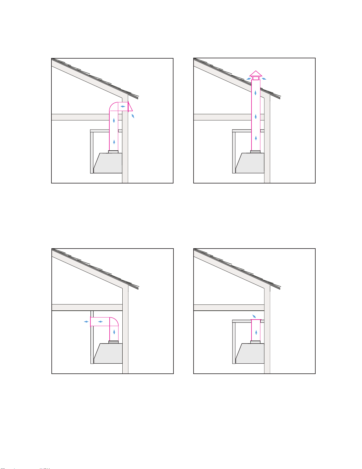
Ducted installation must exhaust outside. Recirculating installations must exhaust back
into the living space.
WARNING: ELECTRICAL SAFETY
This appliance must be connected to a properly grounded, dedicated 120v 60hz 15amp
circuit by a qualified electrician in accordance with all applicable codes and regulations.
Never use any external speed control device.
Never use any extension cord or temporary wiring.
The appliance must be protected by a properly sized circuit breaker or time delay fuse.
CAUTION - DURING INSTALLATION
All installation work and electrical wiring must be done by qualified people in accordance with
all applicable codes and standards, including fire rated construction.
(chimney) of the fuel burning equipment to prevent backdrafting.
Follow the cooking equipment manufacturer’s guidelines and safety standards such as those
published by the National Fire Protection Association (NFPA) and the American Society of
Heating, Refrigeration, and Air Conditioning Engineers (ASHRAE) as well as all local code
authorities.
WARNING: TO REDUCE RISK OF A RANGETOP GREASE FIRE:
a. Never leave the cooking surface unattended. Boil overs, spills and splatter may ignite or
create smoke. Heat oils slowly on low or medium heat settings.
b. Always turn the hood on before you begin cooking.
c. Clean the hood frequently. Keep filters, fans and surfaces free of grease.
d. Use pan sizes appropriate for each burner.e.prepared.
e. Use high heat only when necessary.
f. Use cookware and utensils designed for the cooking style, type and amount of food.
safety first
4

safety first continued
5

safety first continued
6

safety first continued
7

THIS HOOD IS DESIGNED TO USE AN 8” ROUND DUCT -
IT MAY BE TRANSITIONED TO A 4” X 14” RECTANGULAR DUCT
NEVER REDUCE DUCT SIZE. UNDERSIZED DUCTING SEVERELY RESTRICTS
AIR FLOW AND HARMS PERFORMANCE.
(Example: the area of an 8” Duct is more than 75% larger than a 6” Duct)
KEEP DUCT RUNS AS SHORT AND STRAIGHT AS POSSIBLE.
AVOID USING FLEXIBLE METAL DUCTING IF RUN IS LONGER THAN 6’.
NEVER USE PLASTIC DUCTING.
USE SMOOTH BORE METAL DUCTING.
MINIMIZE THE NUMBER OF FITTINGS (see chart).
WHEN YOU MUST USE FITTINGS, TRY TO SEPARATE THEM WITH SECTIONS OF
4’ OR MORE OF STRAIGHT DUCT.
ALWAYS FOLLOW THE MANUFACTURER’S GUIDELINES FOR THE COOKING
EQUIPMENT YOU ARE VENTING.
IF MAKE UP AIR CONTROL DAMPERS ARE REQUIRED, POSITION THE SENSOR
IN A STRAIGHT RUN OF DUCT IDEALLY WITH 4’ OF STRAIGHT DUCT BETWEEN
EACH SIDE OF THE SENSOR AND A DUCT FITTING. REMEMBER TO INCLUDE
POWER AND CONTROL WIRING FOR THIS IN YOUR PLANS.
ADHERE TO ALL LOCAL BUILDING CODES AND ORDINANCES.
USE THE WORKSHEET THAT FOLLOWS TO HELP CALCULATE THE
TOTAL EQUIVILENT FEET OF YOUR DUCT RUN.
TOTAL EQUIVILENT FEET SHOULD BE LESS THAN 100’.
a few simple rules to plan your ductwork
8

DUCT PIECE DESCRIPTION MULTIPLIER QTY USED
1’ of 8” Round Duct
1’ of 4“ x 14” Rect. Duct
8” 90 Degree Elbow
8” 45 Degree Elbow
4” x 14” 90 Degree
4” x 14” 45 Degree
4” x 14” x 8” Round
4” x 14” x 8” Round 90 Degree
8” Round Wall Cap w Damper
4” x 14” 90 Wall cap w Damper
8” Round Roof Cap
1
1
12
7
14
8
2
4
24
24
33
TOTAL EQUIVALENT FEET SHOULD BE LESS THAN 100
CAUSING AIR TO CHANGE DIRECTION CAUSES TURBULENCE AND RESTRICTS FLOW IN A SYSTEM.
IF USING FLEXIBLE METAL DUCT - INCREASE ALL MULTIPLIERS BY 50% (12 BECOMES 18 - ETC.)
THIS EASY TO USE WORKSHEET IS FOR 1000 CFM OR LESS.
UNDER “QTY USED” ENTER HOW OF EACH SECTION YOU WILL BE USING.
IN THE FIRST TWO ROWS - ENTER HOW MANY FEET OF EACH TYPE OF STRAIGHT DUCT YOU WILL
BE USING (I.E. FOR 20 FT ENTER 20, FOR 30’ ENTER 30).
ENTER THE NUMBER OF EACH TYPE OF TURN YOU ARE USING AND THE TYPE OF END CAP.
MULTIPLY ACROSS EACH ROW THE “MULTIPLIER” x “QTY USED” TO GET THE EQUIVALENT FEET
FOR THOSE COMPONENTS.
ADD UP ALL THE VALUES IN THE “EQUIVALENT FEET” COLUMN.
estimating total equivalent feet in a duct
EQUIVALENT
FEET
9

typical installation examples
10
WALL EXHAUST ROOF EXHAUST
SOFFIT EXHAUST CABINET TOP EXHAUST
RECIRCULATION EXHAUST MUST BE RETURNED TO THE SPACE
RECIRCULATION VENTED

dimensions
11
40-3/8''
12''
3''
5-31/32”
46-3/8''
12''
19-1/4''
Ø7-27/32”
Front of hood Side of hood
Top of hood
“A”
“B”
MODEL DIM “A” DIM “B”
XOIL48KS

highs and lows
12
All range hoods have a recommended range of installation height over the cooking surface.
RECOMMENDED
MOUNTING HEIGHT
ABOVE
GAS COOKTOPS
27” to 32”
It is important to install the hood at the proper mounting height. Hoods mounted too low
could result in heat damage and fire hazard; while hoods mounted too high will be hard to
reach and will lose its performance and efficiency.

switching top and rear venting
13
TO CONVERT THE UNIT FROM TOP EXHAUST TO REAR EXHAUST
FOLLOW THESE SIMPLE STEPS:
1. Unplug the quick disconnect coupling that supplies power to the motor.
2. Remove the eighteen (18) screws that fasten the blower assembly and filler plate
to the hood.
3. Remove the blower assembly and filler plate, invert 180 as shown and fasten in
place using the eighteen (18) screws previously removed.
4. Reconnect the quick disconnect plug.
180°
o

the cut out
14
To install the hood into a custom canopy or cabinet, refer to the cutout dimensions above
for your particular model.
46-1/2”
19-7/16"

installation
15
4x
B
B
H
H
2x
BEFORE FITTING THE HOOD INTO THE CABINET:
1. Remove the four (4) screws holding the side bracket (B)
in place. Remove the brackets and set aside.
2 Remove the two (2) screws holding the bracket (H) in place
and tilt down.

installation continued
16
1/4”
1-
1/8
”
8x
INSERT THE HOOD INTO THE CUTOUT
FASTEN THE HOOD IN PLACE
Using four (4) screws along the inside front edge
and four (4) screws in the back corners as shown

electrical connection
17
1. Route the power cord to the junction box inside the hood.
2. Using listed conduit fittings and connectors, connect the power supply to the box and each line
to the appropriate wire following this color convention:
BLACK = HOT LEG
WHITE = NEUTRAL
GREEN/YELLOW = GROUND
Polarity must be observed.
Unit must be properly grounded.
Use a double throw disconnect switch.
3. Replace the box cover
4. Replace the Anti-grease Baffles.
All wiring must be in compliance with
nathional electrical code,
ANSI/NFPA 70-1999
and all local codes and
regulations.

maintenance
18
Regular cleaning and maintenance is the key to long life and peak performance of
any equipment.
ANTI-GREASE BAFFLE FILTERS: Your XO hood is equipped with stainless steel
pro-style baffle filters designed to capture grease from cooking. The baffles are easily
removed for cleaning either by soaking in a warm, mild dish detergent solution, rinsing
thoroughly and drying - or - by washing in your dishwasher.
TO REMOVE THE BAFFLES:
1. Pull down on the release latch (shown left)
2. Lower the front edge of the baffle
3. Pull forward and remove
4. To replace, insert the rear of the baffle, holding the
latch open, swing the the front up into place and
release the latch.
The importance of this simple process is essential for
two reasons. First to help keep your kitchen clean and
healthy, but it is also critical to minimize the risk of fire.
Baffle filters should be cleaned at least once every 2 months, more frequently depending
on the type of cooking performed and the build up of grease.
CLEANING STAINLESS STEEL:
Do not use corrosive detergents, abrasive detergents or oven cleaners.
Do not use any product containing chlorine bleach or any product containing chloride.
Do not use steel wool or abrasive scrubbing pads which will scratch and damage surface.
Cleaning Stainless Steel Clean periodically with warm soapy water and clean cotton cloth
or micro fiber cloth. Always rub in the direction of the stainless steel grain. To remove
heavier grease build up use a liquid degreaser detergent. After cleaning use a non-abrasive
stainless steel polish/cleaners, to polish and buff out the stainless luster and grain. Always
rub lightly, with a clean cotton cloth or a micro fiber cloth and buff in the direction of the
stainless steel grain.
Any painted surfaces should be cleaned with warm water and detergent only.

maintenance continued
19
LED LIGHT REPLACEMENT
The LED light modules are held in place
by spring clips and pull down directly
from the housing.
Unplug the plastic molex connector.
Plug in the new fixture and
snap back into place.

easy to operate
20
BUTTON : Controls the LED lights. There are three illumination levels.
Press the button Once for HIGH; Twice for MEDIUM; Three times for LOW; Four times for OFF.
BUTTON 0: Turns both the Blower and Lights On and Off
BUTTON 1: Blower motor operates on LOW speed.
BUTTON 2: Blower motor operates on MEDIUM speed.
BUTTON 3: Blower motor operates on HIGH speed.
POWER BOOST
Press and Hold BUTTON 3 for 2 seconds.
This will increase airflow to a fourth and even higher speed for 10 minutes.
When activated the button will blink to alert you it is running.
After 10 minutes the blower speed will return to its last setting.
To manually stop the
POWER BOOST
before 10 minutes has elapsed:
Press BUTTON 3 and it will revert to HIGH speed, or
Press BUTTON 0 to shut the blower off completely
NOTE: The POWER BOOST function will operate even when the hood is off.
BUTTON T: Activates and Deactivates the TIMER Function
Pressing BUTTON T (whether the blower is off or running) will cause the motor to run at LOW speed
for 5 minutes before shutting off the blower and lights automatically.
While the TIMER is activated, you can change speed or engage POWER BOOST, the hood will still
shut off after 5 minutes.
To manually turn the the unit off before 5 minutes has elaped:
Press
OPTIONAL REMOTE CONTROL (purchased separately)
The remote control must be synchronized prior to use.
To synchronize the remote control with the hood follow these simple steps:
1. Standing near the hood, while it is not running, press and hold BUTTON
on the hood for 4 seconds -the button should start to blink for 5 seconds.
2. When the button on the hood starts to blink, Press any button on the remote.
The hood and remote are now synchronized.
3. If the synchronization fails for any reason, repeat steps 1 &2
BUTTON T or BUTTON 0.
Your XO range hood is controlled by
these electronic push buttons which
illuminate when activated.
XOVREMOTE1
Table of contents
Popular Fan manuals by other brands

izzy
izzy IZ-9031 instruction manual

LUCCI
LUCCI NEWPORT Installation, operation, maintenance & warranty information

SLE
SLE SLE5000 Model J user manual

Goldair
Goldair GCPF130 operating instructions

Fakir
Fakir prestige 360 Rotating operating instructions

Kichler Lighting
Kichler Lighting Cadence instruction manual

Minka-Aire
Minka-Aire Mystique F611 instruction manual

Carrier
Carrier XCT7 40VH A-7G Series Installation and owner's manual

Harbor Breeze
Harbor Breeze ECHOLAKE 42080 manual

Schako
Schako AQUARIS SILENT Installation, Mounting and Maintenance

Pelonis
Pelonis FS40-8M owner's manual

Duraflo
Duraflo 60PRO130 manual