XOCECO TA2933 User manual

SERVICESERVICE
MANUALMANUAL

0
Contents
Safety Instruction………………………………………………………………………………1
X-ray radiation protection……………………………………………………………………..1
Safety Measures……………………………………………………………………………………..2
Points of attention for product safety………………………………………………………………3
Alignment procedures………………………………………………………………………4
Adjustment equipment……………………………………………………………………..5
Adjustment instruction…………………………………………………………………………5
Factory adjustment method………………………………………………………………………..5
IF amplification adjustment…………………………………………………………………….5
B+ confirmation…………………………………………………………………………………….5
AGC adjustment…………………………………………………………………………………..5
Sound detection…………………………………………………………………………………….6
Adjustment of Focus Potentiometer……………………………………………………………….6
Alignment of line certer…………………………………………………………………………..6
Field amplitude, field S alignment, field center, line amplitude, E/W alignment etc. ……………6
Adjustment of screen-grid VG2……………………………………………………………………….7
White balance adjustment……………………………………………………………………..7
Inspection of the high voltage and filament voltage………………………………………………….7
Inspection of X-ray protection………………………………………………………………….7
Inspection of beam current…………………………………………………………………..7
Inspection of AV function……………………………………………………………………………….7
Wiring diagram…………………………………………………………………………….8
IC block diagram…………………………………………………………………………..9
Schematic diagram…………………………………………………………………………….11
Electrical parts list ……………………………………………………………………………..13
Assembly drawing of complete set …………………………………………………………34
Detail list of Assembly drawings……………………………………………………………35

1
Attention: This maintenance manual is only intended for the professional maintenance
personnel to take reference with. Before repairing TV set please carefully read
the following points of attention.
Safety Instruction
Before fixing and aligning this set, please read the following “Points of attention for
Safety “, “Points of attention for Safety of Components” and “X-ray Radiation
Protection“.
Points of attention for Safety
1. Because the city power is connected directly to the hot earth of power supply PCB, in order to
avoid electric shock or damage to instruments, an isolate transformer must be applied during the
fixing procedure.
2. Before moving the CRT, graphite layer conductor must be discharged.
3. Before replacing any components, the power plug must be taken out from the power supply
socket.
4. Before replacing large power resistor, 10mm high must be kept between resistor and PCB.
Points of attention for the components safety
There are many electric and mechanical components on the PCB that are related with the
safety features. These features are not easily visible. Replacement parts that have special safety
characteristic are indicated in the Instruction Manual. Electric components with such features will be
labeled with shadow or labeled with in the detail list. When changing these components, please
refer to the detail list in the manual. Components that have different specification from that in the
detail list may not have the same safety features. They may cause electric shock, fire, increase of
X-ray radiation or other damage.
1. Safety instruction
Before fixing or aligning this set, please read the following “ X-ray radiation protection”, “Safety
measures” and “Points of attention for products”.
1.1 X-ray radiation protection
1.1.1 Too high voltage will produce radiation harmful to human health. To avoid such risk, the
high voltage should be regulated within the limited value. For 25”, the normal value of beam
current should be 26.5 kV at 1.3 mA, for 29”, 29kV at1.4 mA and for 29” pure flat TV set,
30kV.
Under any circumstances, the high voltage should not exceed 31kV (25”), 33 kV (29”), 35kV

2
(29” pure flat). When the TV set needs to be fixed, please follow the inspection procedures of
high voltage in item 4.11 under this instruction ”Inspection of high voltage”. It is suggested that
the value of high voltage be recorded as part of maintenance work. It is most essential at the
same time to use precise and dependable high voltage meter.
1.1.2 This set is equipped with X-ray over radiation (FS) protection circuit to prevent over radiation
of X-ray in the case of abnormal increase of B+ voltage in the set. Whenever fixing the set,
FS circuit must be checked according to the inspection procedures as in item 4.11.5 of this
instruction, ”X-ray radiation protection test” to make sure the circuit functions well.
1.1.3 The only source of TV set producing X-ray is CRT. To avoid X-ray radiation during the whole
process, the exact same type of CRT designated in the detail list must be replaced, when
there is a need to change CRT.
1.1.4 When deciding on the same type of 4, as some components of this TV set are related to the
safety characteristic, please read the “Points of attention for products safety” before changing
the components, for the sake of safety.
1.2 Safety measures
1.2.1 When the TV set is working, the high voltage will be as high as approximately 31kV. When
adjusting the set after removing the cover or opening the back cabinet there will be risk of
electric shock, so
a) Before detaching the anode cap, please discharge it several times by grounding the anode
of CRT to earth many times to avoid electric shock.
b) Before moving the CRT, its anode must be thoroughly discharged. The CRT is a high
vacuum part. Once broken, its fragments will fly out violently. Therefore it must be very
careful in dismantling and loading it.
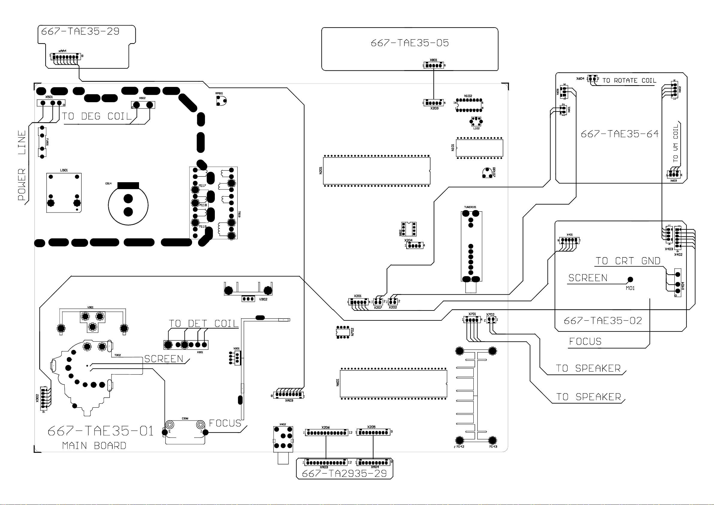
1.2.2 There are a lot of electronic and mechanical components in PCB that have safety related
features. They are indicated with shadow in the circuit diagram. Please carefully read the
detail list before changing these components.
1.2.3 If the fuse is blown, please change it for the one designated in the list of components.
1.2.4 When changing resistors of 1w or bigger than 1w in PCB, make sure to separate them from
the PCB by10 mm.
1.2.5 Make sure that the wire stays far away from the high voltage or high temperature
components.
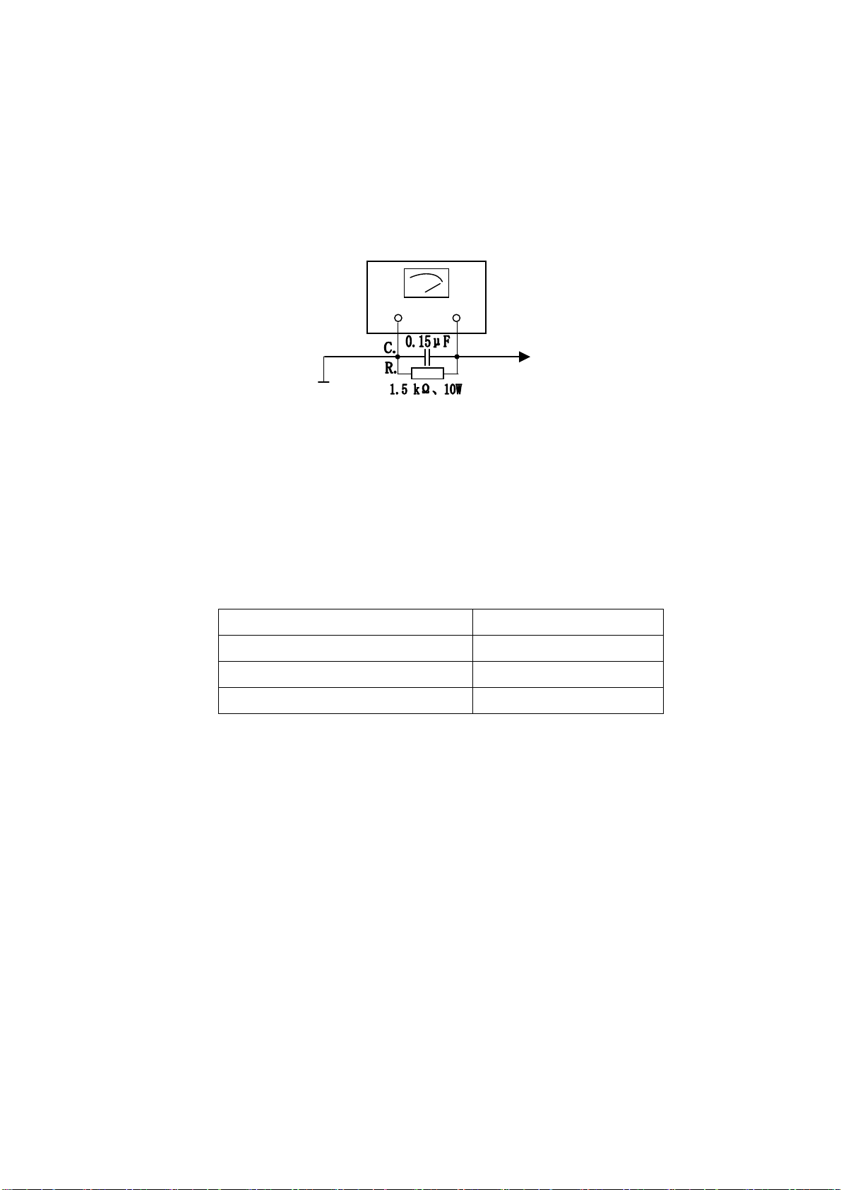
1.2.6 Check for the AC leakage current of the metal components exposed out of the cover such as
antenna terminal, screw, metal surface and control axis. Make sure that the cabinet of TV set
is absolutely safe in operation, free from any risk in electric shock. Insert the power supply
plug directly into the 220v AV socket (No isolate transformer will be applied during the test).
Use an AC voltage meter with sensitivity of 5 kΩor higher per volt to measure the leakage
current according to the following steps:
First, connect in parallel a resistor of1.5 kΩ,10 W resistor and a 0.15 μF capacitor (AC type)

3
between the known good earthing connector (such as underground metal tube) and the
exposed metal parts out of the cabinet. Measure AC voltage across both terminals. Then
exchange the two pins of AC before re-measuring every exposed metal parts. The measured
value of voltage should not exceed 0.3V effective value, which corresponds to current.0.2mA
If the value exceeds this specified value, aligning must be made at once.
Figure1
1.2. 7 DC voltage breakdown test
The following touchable parts must be subject to 1s anti voltage test before packing. The
voltage is applied between the plug pin of the power supply and the exposed metal parts for
the test and the volt value should be AC 3000V.
Parts designation: Position:
Antenna terminal Back cover
External cover screw Back cover
AV interface Back cover, sides
1.3 Points of attention for product safety
There are many electric and mechanical parts in this PCB that are related to safety. However,
they are often neglected from visual look. For changing the high voltage and high power parts,
very often it’s impossible to provide them with effective “X-ray radiation” protection. All these
exchange parts with safety characteristic are designated in the detail list. All the electronic
parts with such characteristics are indicated with shadow in the circuit diagram.
When changing these parts, please carefully check the detail list.
A
C Volt Mete
r
Good Earth Connect Point
(Such as underground metal etc)
This detector is placed
respectively at every
exposed metal parts.

4
2 Flow chart of Adjustment and aligning
EEPROM
B+volt and 5V-3V
check
Field amplitude,
field linearity
Line amplitude
and east-wes
t
RF AGC setup
Sound check
Focus course
VG2 adjustment
White balance and
Line field, center and
field amplitude, reset
Line amplitude and
Focus fine adjustment
check
High volt
Filament volt
X-ray
Picture &
Brightness
White
Color
Set Av terminal
Check of key
Check on
Assembly
Safety check
casse
Com
IF Test
Dark balance
SCART JACK
Earphone
jack
Sound power
See Fig.2
Set R378 to optimize
Field center

5
3. Alignment Equipment
3.1 DC Current Stabilizer Power Supply PAB18-1.8
3.2 Audio Frequency Voltage Meter
3.3 Oscillograph
3.4 High Voltage Meter
3.5 Digital Multi-meter
3.6 AC breakdown test meter
3.7 IFT Signal Gene
4. Alignment Instruction
4.1 Factory Alignment Methods
4.1.1 Push composed keys →--/--- →to enter factory menu.
4.1.2 There are totally three pages of factory menu. Turn the page by pushing “MENU”, Move the
items by CH+/CH- key, Adjust the value by VOL+/VOL-. After adjustment, push “OK” for save.
4.1.3 The method to quit factory menu: Under the item VCT in SERVICE XOCECO-50 Hz, push
EXIT: OK
4.2 IF amplifier alignment
a) Connect the positive pole of TP5. C219 to DC 5v, TP2 or TP7 to positive pole DC 8v, TP6 to
earth, TP4 to multi-meter.
b) Connect 38.9M, PAL DK IF signal to TP1 through 1000p capacitor, adjust IFT L102 with zero
inductance screwdriver, to make the readout of multi-meter as 2.5V±0.1 V.
c) Connect 33.9M SECAM L IF signal to TP1 through 1000P capacitor, apply voltage 5v at TP1,
TP3, TP8, adjust RP101 with zero inductance screwdriver, to make the readout of
multi-meter as 2.5V±0.1 V.
d) After adjustment, connect the IF line disconnect point of tuner, seal L102 with wax, point glue
RP 101.
4.3 B+ confirmation
Determine the B+ voltage by DC meter, DC 200V ( C503 two poles) , the value should be 135
V±0.5.
4.4 AGC adjustment
4.4.1 Receive D-8 signal 60db, determine the voltage of positive testing pole of C114 with DC
voltage meter.
4.4.2 Adjust potentiometer RP107, to make the voltage readout of voltage meter to be 4.1 V±
0.1V.
4.4.3 Input 100db from antenna, and the picture should not appear as asynchronized and
distorted. Input 35db-40db weak signal, and the color should not disappear, the picture
should be synchronized, and the sound is normal.

6
4.5 Sound inspection
4.5.1 Receive 1kHz sound signal 100% modulated and connect X701 with 8Ωfalse resistances
(load). Connect sound voltage meter and Oscillograph to two poles of the false resistances.
4.5.2 Turn the sound to the biggest volume. Balance the sound and set the high/low sound to the
middle, MSS OFF, DBE OFF, and the sound power should be ≥7 W×2(about 7.5 Vrms),
distortion≤7% (A slight peak cutting at maximum sound sine wave is allowed.)
4.6 Alignment of focus potentiometer
4.6.1 Pre-warm the TV set for 30 minutes.
4.6.2 Receive the signal from testing card.
4.6.3 Push the key of picture mode to place analog in “dynamic”.
4.6.4 Adjust potentiometer of FOCUS on the FBT to make the picture to be best focused.
4.7 Alignment of line center
4.7.1 Receive 50 HZ signal from video head.
4.7.2 Enter the factory menu RGB HOR. POSITION item under AV status, adjust amplitude of RGB,
and make the picture to be symmetry. Then save.
4.7.3 Receive 60Hz video signal and enter the factory menu RGB HOR.POSITION item under AV
status. The adjusting method of POSITION is same as 4.7.1~4.7.2.
4.7.4 Adjust separately under following four modes
a)50 Hz 4: 3;
b)60 Hz 4: 3;
Of which Vert position is unnecessary for readjustment after setup at the initial value. Adjust
the value of R378 to optimize it (set it up during the production in the factory).
4.8 Field amplitude, field S alignment, field center, line amplitude, E/W alignment etc.
Enter the corresponding item of factory menu and adjust the geometric distortion until accepted.
Hor Amplitude
Cushion
Trapeze
Angle
Bow
Hor Symmetry
Hor Corners
Vert position
Vert Amplitude
Vert S-Correction
Vert S-Symmetry

7
The adjustment result should satisfy the scan linear geometric distortion and over scan (rate of
recurrence)
4.9 Adjustment of screen-grid Focus and VG2
4.9.1 Adjust FBT Focus pole potentiometer until picture is clear.
4.9.2 Enter factory menu Cathode current (G2) item, (AV should be kept empty then), push VOL+,
change to bright horizontal line and adjust the potentiometer of the line pack acceleration pole
in such a way that the bight horizontal line becomes slightly bright.
4.10 White Balance Adjustment
4.10.1 Enter “Cutoff ref” adjustment of factory menu. It’s enough only to fine adjust the dark
balance. Under 4.5 Niete, color temperature 12000K+8MPCD(X=0.270,Y=0.283).
4.10.2 Enter Drive ref item adjustment of factory menu. The bright balance will be automatically
adjusted at a certain white coordinate place. Under 60 Niete, color temperature
2000K+8MPCD(X=0.270,Y=0.283).
4.11 Inspection of the high voltage and filament voltage
4. 11. 1 Connect high voltmeter between the high voltage cap and the earth. Measure the filament
voltage with an actual value and effective voltage meter.
4.11.2 Receive D35 signal, set the picture mode at “dynamic”, and measure the high voltage and
filament voltage. The voltage for 29” “Yongxin” extra pure flat should be: high voltage- 29 kV
±0.5 kV; 29″pure flat, high voltage- 30 kV±0.5 kV,filament voltage- 6.3±0.3 Vrms.
4.12 Inspection of X-ray protection
4.12.1 Receive normal picture.
4.12.2 Push switch S301. The line scan should stop vibrating and shut the set off.
4.12.3 Shut off the main power supply, re-power it on in 30 seconds. It should be back to normal.
4.13 Inspection of beam current
Receive D35 signal, set the picture mode at “dynamic”, and measure the two terminals of TP9,
TP10. For ultra pure flat it should be ≤1.6 V, and for 29″pure flat, ≤1.7 V.
4.14 Inspect ion of AV function
VIDEO IN: 1 Vp-p 75Ω, AUDIO IN: -8 dBm±3 dBm >47 kΩ.
As per instruction manual, connect audio and video equipment with AV terminal of the set to
be tested. The inter-connection should be made to meet the following requirements:
VIDEO IN: 1 Vp-p 75Ω, AUDIO I: -8 dBm±3 dBm >47 kΩ.


13
ELECTRICAL PARTS LIST
MAIN BOARD
SYMBOL PART NO. DESCRIPTION
782-TAE35-010A MAIN PCB
CRYSTAL
G601 329-61801-00 HC49US 18.432MHZ
G201 329-62001-00 CAST5 20.25MHZ
RECTIFIER
D506 340-80010-00 RUIP
D501 340-80019-00 T3SB60
DIODE
D705 340-00001-00 1N4148
D527 340-00288-003 TFR155
D304 340-00014-00 RGP10J
D315 340-00060-00 RGP25K
D101 340-00170-00 MA859
D513 340-00256-00 BYT56M
D514 340-00283-00 TRU3YX
D515 340-00283-00 TRU3YX
D516 340-00284-00 TRU4YX
D526 340-00291-00 TEU2YX
D502 340-00292-00 TRU3A
D312 340-00297-00 ERD07-15
D511 340-00309-00 RG4
D204 340-00001-003 1N4148
D601 340-00001-003 1N4148
D701 340-00001-003 1N4148
D602 340-00001-003 1N4148
D702 340-00001-003 1N4148
D525 340-00001-003 1N4148
D508 340-00001-003 1N4148
WARNING: BEFORE SERVICING THIS CHASSIS, READ THE “X-RA
Y
RADIATION PERCAUTION”, “SAFETY PRECAUTION” AND “RPODUC
T
SAFETY NOTICE” ON PAGE 1&2 OF THIS MANUAL.
CAUTION: 1. The shaded areas makes in the schematic diagram and the parts list designate components
which have special characteristics important for safety and should be replaced only with
type identical to those in the original circuit or specified in the parts list. Before replacing
any of these components, read carefully the PRODUCT SAFETY NOTICE on page 2.
2. Do not degrade the safety of the receiver through improper servicing.

14
SYMBOL PART NO. DESCRIPTION
D512 340-00001-003 1N4148
D503 340-00001-003 1N4148
D504 340-00001-003 1N4148
D509 340-00001-003 1N4148
D510 340-00001-003 1N4148
D507 340-00001-003 1N4148
D704 340-00001-003 1N4148
D524 340-00001-003 1N4148
D402 340-00001-003 1N4148
D403 340-00001-003 1N4148
D528 340-00001-003 1N4148
D361 340-00001-003 1N4148
D100 340-00001-003 1N4148
D307 340-00010-003 S5295G
D302 340-00010-003 S5295G
D313 340-00014-003 RGP10J
D303 340-00014-003 RGP10J
D301 340-00014-003 RGP10J
D363 340-00014-003 RGP10J
D305 340-00086-003 TVR-1B
REGULATED DIODE
D310 340-51850-00 HZ18-3
D202 340-50560-00 HZ6B1
D203 340-50560-00 HZ6B1
D360 340-50470-003 HZ5B1
D308 340-50470-003 HZ5B1
D309 340-50470-003 HZ5B1
D205 340-50510-003 HZ5C2
D206 340-50510-003 HZ5C2
D518 340-50560-003 HZ6B1
D517 340-50610-003 HZ6C2
D523 340-50650-003 HZ7A2
D603 340-50810-003 HZ9A2
D314 340-50910-003 HZ9C1
D201 340-50910-003 HZ9C1
D521 340-50910-003 HZ9C1
D505 340-51560-003 HZ16-1
TRANSISTOR
V106 343-10150-10 2SA1015Y
V503 343-01800-00 KSE180 TO-126
V506 343-01800-00 KSE180 TO-126
V109 343-12040-00 RN1204
V507 343-16680-00 2SA1668
V504 343-24820-00 2SC2482
V301 343-25390-00 2SD2539

15
SYMBOL PART NO. DESCRIPTION
V302 343-38520-00 2SC3852
V101 343-23690-004 PH2369
D519 343-00420-404 SFORIB42
V501 343-04000-304 2SD400 E/F
V304 343-10150-104 2SA1015Y Pr2.5
V303 343-10150-104 2SA1015Y Pr2.5
V201 343-10150-104 2SA1015Y Pr2.5
V502 343-10150-104 2SA1015Y Pr2.5
V702 343-10150-104 2SA1015Y Pr2.5
VA01 343-10150-104 2SA1015Y Pr2.5
V405 343-10150-104 2SA1015Y Pr2.5
V406 343-10150-104 2SA1015Y Pr2.5
V407 343-10150-104 2SA1015Y Pr2.5
V204 343-18150-114 2SC1815-Y
V205 343-18150-114 2SC1815-Y
V206 343-18150-114 2SC1815-Y
V508 343-18150-114 2SC1815-Y
V102 343-18150-114 2SC1815-Y
V103 343-18150-114 2SC1815-Y
V107 343-18150-114 2SC1815-Y
V408 343-18150-114 2SC1815-Y
V409 343-18150-114 2SC1815-Y
V108 343-18150-114 2SC1815-Y
V505 343-18150-114 2SC1815-Y
V363 343-18150-114 2SC1815-Y
V104 343-18150-114 2SC1815-Y
V207 343-18150-114 2SC1815-Y
V110 343-18150-114 2SC1815-Y
V305 343-23830-604 2SC2383-0
V105 343-27170-004 2SC2717
CERAMIC CAPACITOR
C526 459-6210K-00 DE0705B102K1K
C204 459-2410R-00 DD308-63F104Z50
C616 459-2051H-10 CC1-08-CH-63V-51pF-J
C617 459-2051H-10 CC1-08-CH-63V-51pF-J
C220 459-2410R-00 DD308-63F104Z50
C203 459-2410R-00 DD308-63F104Z50
C100 459-2112H-102 CC45-CH1H121JYR
C215 459-2002C-102 CC45-CH1H020CYR
C214 459-2002C-102 CC45-CH1H020CYR
C647 459-2020H-102 CC45-CH1H200JYR
C646 459-2020H-102 CC45-CH1H200JYR
C644 459-2056H-102 CC1-08-CH-63V-56pF-J
C643 459-2056H-102 CC1-08-CH-63V-56pF-J
C202 459-2110H-102 CC45-CH1H101JYR

16
SYMBOL PART NO. DESCRIPTION
C415 459-2110H-102 CC45-CH1H101JYR
C271 459-2122H-102 CC45-CH1H221JYR
C344 459-2122H-102 CC45-CH1H221JYR
C411 459-2122H-102 CC45-CH1H221JYR
C412 459-2122H-102 CC45-CH1H221JYR
C413 459-2122H-102 CC45-CH1H221JYR
C201 459-2122H-102 CC45-CH1H221JYR
C313 459-2133K-902 RBU07SL331K-H46CA
C316 459-2133K-902 RBU07SL331K-H46CA
C642 459-2147H-902 CC1-12-SL-63V-471J
C640 459-2147H-902 CC1-12-SL-63V-471J
C641 459-2147H-902 CC1-12-SL-63V-471J
C516 459-2168K-002 CK45-B1H681KYR
C525 459-2210K-002 CK45-B1H102KYR
C110 459-2210K-002 CK45-B1H102KYR
C151 459-2210K-002 CK45-B1H102KYR
C738 459-2210K-002 CK45-B1H102KYR
C739 459-2210K-002 CK45-B1H102KYR
C637 459-2215K-002 CT1-06-2B4-63V-152K
C639 459-2215K-002 CT1-06-2B4-63V-152K
C638 459-2215K-002 CT1-06-2B4-63V-152K
C606 459-2233K-002 CT1-08-2B4-63V-332K
C607 459-2233K-002 CT1-08-2B4-63V-332K
C311 459-2247R-002 CT1-08-2E4-63V-472Z
CA12 459-2247R-002 CT1-08-2E4-63V-472Z
CA15 459-2247R-002 CT1-08-2E4-63V-472Z
C538 459-2310R-002 CK45-F1H103ZYR
C539 459-2310R-002 CK45-F1H103ZYR
C561 459-2310R-002 CK45-F1H103ZYR
C563 459-2310R-002 CK45-F1H103ZYR
C140 459-2310R-002 CK45-F1H103ZYR
C141 459-2310R-002 CK45-F1H103ZYR
C142 459-2310R-002 CK45-F1H103ZYR
C143 459-2310R-002 CK45-F1H103ZYR
C608 459-2310R-002 CK45-F1H103ZYR
C609 459-2310R-002 CK45-F1H103ZYR
C713 459-2310R-002 CK45-F1H103ZYR
C118 459-2310R-002 CK45-F1H103ZYR
C116 459-2310R-002 CK45-F1H103ZYR
C117 459-2310R-002 CK45-F1H103ZYR
C128 459-2410R-002 DD308-63F104Z50
C569 459-2410R-002 DD308-63F104Z50
C122 459-2410R-002 DD308-63F104Z50
C267 459-2410R-002 DD308-63F104Z50
C269 459-2410R-002 DD308-63F104Z50
Table of contents
Other XOCECO TV manuals

XOCECO
XOCECO LC-15H3 User manual

XOCECO
XOCECO LC22K9 User manual

XOCECO
XOCECO PS42K8 User manual

XOCECO
XOCECO LC23K6 User manual

XOCECO
XOCECO PH-50HU31 User manual

XOCECO
XOCECO LC17H3S User manual

XOCECO
XOCECO LC-27W18S User manual

XOCECO
XOCECO TK1337D User manual

XOCECO
XOCECO TK2055D User manual

XOCECO
XOCECO TK2016 User manual

XOCECO
XOCECO TK2026 User manual

XOCECO
XOCECO LC20H3D User manual

XOCECO
XOCECO NXT1333 User manual

XOCECO
XOCECO TQ2426 User manual

XOCECO
XOCECO LET3250 User manual

XOCECO
XOCECO LET2751 User manual

XOCECO
XOCECO TS2019 User manual

XOCECO
XOCECO LC30B1 User manual

XOCECO
XOCECO LC27K6 User manual

XOCECO
XOCECO LC-23K7 User manual